EP2276592B1 - La régulation de métal liquide en utilisant des bouchons flottants - Google Patents
La régulation de métal liquide en utilisant des bouchons flottants Download PDFInfo
- Publication number
- EP2276592B1 EP2276592B1 EP09735817.0A EP09735817A EP2276592B1 EP 2276592 B1 EP2276592 B1 EP 2276592B1 EP 09735817 A EP09735817 A EP 09735817A EP 2276592 B1 EP2276592 B1 EP 2276592B1
- Authority
- EP
- European Patent Office
- Prior art keywords
- plug
- metal
- crucible
- liquid
- interior
- Prior art date
- Legal status (The legal status is an assumption and is not a legal conclusion. Google has not performed a legal analysis and makes no representation as to the accuracy of the status listed.)
- Not-in-force
Links
- 229910001338 liquidmetal Inorganic materials 0.000 title claims description 16
- 229910052751 metal Inorganic materials 0.000 claims description 60
- 239000002184 metal Substances 0.000 claims description 60
- 229910045601 alloy Inorganic materials 0.000 claims description 35
- 239000000956 alloy Substances 0.000 claims description 35
- 238000006073 displacement reaction Methods 0.000 claims description 33
- 238000000034 method Methods 0.000 claims description 33
- 239000007788 liquid Substances 0.000 claims description 16
- 238000005266 casting Methods 0.000 claims description 14
- 239000000919 ceramic Substances 0.000 claims description 13
- 238000002844 melting Methods 0.000 claims description 13
- 230000008018 melting Effects 0.000 claims description 13
- 230000000977 initiatory effect Effects 0.000 claims description 9
- PNEYBMLMFCGWSK-UHFFFAOYSA-N aluminium oxide Inorganic materials [O-2].[O-2].[O-2].[Al+3].[Al+3] PNEYBMLMFCGWSK-UHFFFAOYSA-N 0.000 claims description 4
- 230000000452 restraining effect Effects 0.000 claims description 2
- 238000010438 heat treatment Methods 0.000 description 6
- 230000000717 retained effect Effects 0.000 description 4
- 239000000155 melt Substances 0.000 description 3
- 238000004891 communication Methods 0.000 description 2
- 150000002739 metals Chemical class 0.000 description 2
- 238000012986 modification Methods 0.000 description 2
- 230000004048 modification Effects 0.000 description 2
- 238000007789 sealing Methods 0.000 description 2
- 241001125929 Trisopterus luscus Species 0.000 description 1
- 230000004075 alteration Effects 0.000 description 1
- 239000004411 aluminium Substances 0.000 description 1
- 229910052782 aluminium Inorganic materials 0.000 description 1
- XAGFODPZIPBFFR-UHFFFAOYSA-N aluminium Chemical compound [Al] XAGFODPZIPBFFR-UHFFFAOYSA-N 0.000 description 1
- 230000000903 blocking effect Effects 0.000 description 1
- 238000009749 continuous casting Methods 0.000 description 1
- 238000004519 manufacturing process Methods 0.000 description 1
- 239000000463 material Substances 0.000 description 1
- 230000007246 mechanism Effects 0.000 description 1
- 230000008569 process Effects 0.000 description 1
- 230000001737 promoting effect Effects 0.000 description 1
- 230000009467 reduction Effects 0.000 description 1
- 229910000601 superalloy Inorganic materials 0.000 description 1
Images
Classifications
-
- B—PERFORMING OPERATIONS; TRANSPORTING
- B22—CASTING; POWDER METALLURGY
- B22D—CASTING OF METALS; CASTING OF OTHER SUBSTANCES BY THE SAME PROCESSES OR DEVICES
- B22D37/00—Controlling or regulating the pouring of molten metal from a casting melt-holding vessel
-
- B—PERFORMING OPERATIONS; TRANSPORTING
- B22—CASTING; POWDER METALLURGY
- B22D—CASTING OF METALS; CASTING OF OTHER SUBSTANCES BY THE SAME PROCESSES OR DEVICES
- B22D41/00—Casting melt-holding vessels, e.g. ladles, tundishes, cups or the like
- B22D41/08—Casting melt-holding vessels, e.g. ladles, tundishes, cups or the like for bottom pouring
-
- B—PERFORMING OPERATIONS; TRANSPORTING
- B22—CASTING; POWDER METALLURGY
- B22D—CASTING OF METALS; CASTING OF OTHER SUBSTANCES BY THE SAME PROCESSES OR DEVICES
- B22D41/00—Casting melt-holding vessels, e.g. ladles, tundishes, cups or the like
- B22D41/14—Closures
- B22D41/44—Consumable closure means, i.e. closure means being used only once
Definitions
- This invention can be applied to the manufacture of cast components in which there is a requirement to control flow of metal into a casting mould.
- bottom pour crucible arrangement typically uses a metallic plug that melts shortly after the metal charge.
- a bottom pour system allows the molten metal to be removed from the bottom of the melt pool, thus minimizing the likelihood of any dross being entrained into the mould.
- US 3188702 discloses an apparatus for vacuum melting and casting metals comprising heating means defining a heating cavity, a melting and bottom pouting crucible assembly in said heating cavity, a supporting structure for said heating means and crucible assembly, a casting mould to accept metal poured from the crucible, and a removable vacuum sealing envelope for the combination of heating means, crucible assembly, supporting structure and casting mould, wherein the crucible assembly is supported on a carrier so as to be insertable into and withdrawable from the base of the heating cavity in removal of said sealing envelope.
- US 3201837 discloses a method of casting metal from a reservoir of molten metal contained in an enclosed ladle having a bottom pouring opening closed by a stopper member, comprising placing said opening in communication with the lower end of a separable, upwardly extending, refractory pouring conduit disposed externally of said reservoir for delivery of metal from the ladle to a mold, placing the opposite end of the pouring conduit in communication with the bottom of a separate mold, creating a first super atmospheric pressure within said pouring conduit sufficient to dislodge said stopper member from said pouring opening, reducing said first superatmospheric pressure to a value substantially equal to ambient atmospheric pressure, creating a second superatmospheric pressure on the molten metal within said ladle in order to cause continued flow of molten metal from the ladle through the pouring conduit and into the mold until the mold is full, relieving said second superatmospheric pressure, and separating the filled mold from the pouring conduit.
- US 3830281 (Snider J ) discloses in the continuous casting of aluminium a series of moulds are supplied with molten metal through individual dip tubes from a common trough system. To approximately synchronise entry of metal to the moulds, the mouth of each dip tube is initially closed by means of a buoyant plug to prevent entry of metal to the dip tube, until a predetermined depth of metal has been established in the trough system.
- there is a method of initiating a pour of a liquid metal into a casting mould that comprises providing a crucible with an interior base having an opening closed by a plug.
- the plug is buoyant in the liquid metal having a metal head below a critical height.
- a displacement body is at least partially immersed in the liquid metal in the interior of the crucible so that the metal head is above the critical height.
- Pour is initiated by at least partially withdrawing the displacement body from the liquid metal until the metal head falls below the critical height.
- a method of initiating a pour of a liquid alloy comprises the steps of filling an interior of a crucible with a displacement plunger and the liquid alloy until a metal head of the liquid alloy exceeds a critical height.
- the crucible has a bottom pour opening with a plug inserted therein.
- the plug is configured to be buoyant within the liquid alloy when the liquid alloy is below the critical height.
- Pour is initiated by at least partially withdrawing the displacement plunger until the metal head drops below the critical height.
- the method further comprises superheating the liquid metal prior to initiating pour.
- the method further comprises melting the metal into the liquid state after positioning the displacement body in the interior of the crucible.
- the method further comprises melting the metal into the liquid state before positioning the displacement body in the interior of the crucible.
- the method further comprises completely withdrawing the displacement body from the liquid metal.
- the method further comprises completely withdrawing the displacement body from the interior of the crucible.
- the method further comprises wherein the plug provided with the crucible is ceramic.
- the method further comprises wherein the plug provided is made of alumina.
- the method further comprises wherein the displacement body is a ceramic bar.
- the method further comprises wherein the plug provided includes an extension passing through the opening in the base of the crucible.
- the method further comprises wherein the crucible and casting mould are moved closer to each other until the extension of the plug contacts the casting mould.
- the method further comprises restraining the plug while melting the metal until the metal head exceeds the critical height.
- the method further comprises the plug is restrained by a latch.
- the method further comprises disengaging the restraint from the plug after the metal head exceeds the critical height.
- This invention can be applied to control the flow of metal into a casting mould, and is especially useful in cases where it is necessary to superheat the alloy before pouring.
- a bottom pour crucible arrangement that uses a metallic plug that melts shortly after the metal charge does not allow the alloy to be superheated in a controllable manner.
- a buoyant plug to release molten alloy from a crucible into a casting mould at a defined and controllable time.
- the plug is preferably manufactured from a material that has a lower density than the alloy being poured (and/or is manufactured with one or more closed interior volumes).
- the plug is placed in an aperture in the base of the melting crucible. Although the plug would normally float in the molten alloy the pressure of the metal over the plug keeps it in place, thus blocking flow of the molten alloy through the aperture in the base of the crucible.
- the size of the hole and the density difference between the alloy and the plug there is a critical head height of alloy required to keep the plug in place.
- the plug is able to float away, allowing the alloy to exit the crucible.
- This initiation event can be undertaken at any time, thus enabling the alloy to be superheated.
- the molten alloy may be contained inside the melting crucible until a particular set of conditions (such as superheating) are reached before the alloy is released into the mould.
- the buoyant plug arrangement does not rely on the melting of the plug, or the use of complex mechanical arrangements to contain the alloy.
- One embodiment is to use a crucible with a hole in the bottom similar to the bottom pour crucibles in use for small bore furnace casting.
- the molten alloy is preferably retained in the crucible by a ceramic plug, manufactured from alumina for example, placed in the bottom of the crucible.
- the density of the plug is engineered so that a metal head greater than the critical head height keeps the plug in place during the superheating portion of the process.
- the head height in the crucible is allowed to fall when the preferred superheat is reached in the metal.
- One method of lowering the metal head below the critical head height is through the use of a movable displacement body that is at least partially immersed in the molten alloy.
- the displacement body might be, for example, a ceramic bar.
- the displacement body is at least partially, if not fully, withdrawn from the molten alloy (and might be completely removed from the interior of the crucible). This changes the amount of the load retaining the plug and it is possible to engineer the density of the plug sufficiently to allow it to be buoyant and float away.
- the molten alloy is now able to exit the crucible through the hole in the bottom of the crucible.
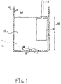
- molten alloy 30 is retained within interior 60 defined by inner wall 56 of a crucible 50. While the present application will utilize the term alloy, it is defined to conclude super alloys and elemental metals unless specifically provided to the contrary.
- Crucible 50 is a bottom pour crucible that defines an opening 55 in the base 58. Molten alloy 30 is retained in the crucible 50 by a ceramic plug 110, manufactured from alumina for example, placed in the opening 55 in the base 58 of crucible 50.
- the density of the plug 110 is engineered so that a metal head "h" greater than the critical head height "H” keeps the plug 110 in place until the controlled initiation of pouring is desired.
- Such pour is not initiated until a superheating condition exists in the molten alloy 30.
- a quantity of un-melted metal is utilized to keep the ceramic plug 110 in place within the opening 55 until the required critical head height "H" of molten metal is provided in the crucible.
- the quantity of un-melted metal can be placed upon the ceramic plug 110 to keep the plug in the opening 55 until the head height of molten metal has taken over holding the plug in a closed position.
- the present application contemplates mechanical mechanisms for latching and/or holding the ceramic plug 110 in a closed position until the desired critical head height "H" of molten metal is accumulated.
- Displacement body 75 occupies a volume such that the metal head "h” is a height 122 that is greater than the critical head height "H” 120 necessary to retain the plug 110 within the aperture 55 in the base 58.
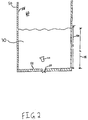
- pour is initiated by at least partially withdrawing the displacement body 75 from the molten alloy 30 as illustrated in FIG. 2 .
- the metal head "h” is a height 118 less than the critical head height "H” 120.
- buoyant plug 110 floats free and molten alloy exits via orifice 55 in the base 58 of crucible 50.
- the displacement body 75 is illustrated as having a paddle shaped cross section, but may take on any of a wide variety of shapes and sizes. While the displacement body 75 is illustrated as fully withdrawn from the interior 60 of the crucible 50 in FIG. 2 , it should be understood that, depending on the fill level and the critical head height "H", the body 75 might only need to be partially withdrawn in order to drop the metal head below a height of "H". That is to say, it is contemplated that the displacement body 75 might still be partially immersed in the molten alloy 30 when the metal head "h” fall below the critical head height "H” to initiate pouring. Also, if preferred, the crucible 50 might have a closed and/or pressurized interior.
- the buoyant (preferably ceramic) plug is modified.
- the plug includes a stem that extends through the hole and further extends beneath the base of the crucible.
- the ceramic mould that receives the molten metal is elevated to contact the plug extension and lift the plug into the crucible.
- the metal can then pour from the crucible into the mould.
- the mould might remain stationary and the crucible might be lowered until the stem contacts the mould and lifts the plug into the crucible.
- the plug 110 and the corresponding seat in the opening 58 are contemplated herein as taking on a variety of sizes and shapes.
- the plug is tapered and matches with a tapered seat in the opening 58.
- the shape of the plug matches the shape of the seat in the opening.
- the present application is not limited to the fore mentioned shapes and also fully contemplates a mismatch between the shapes of the plug and the seat so as to lead to a sharp edge surface seal.
- the plug and the corresponding seat are tapered and the plug is relatively large in size in comparison to the size of the opening 58 for the discharge of molten metal.
- the plug Upon reduction of the head height of molten metal the plug is displaced from the seat and the annular area between the tapered surface of the plug and its tapered seat becomes of a size greater than the pouring orifice, the primary pressure drop shifts to the pouring orifice and the plug floats away from the seat.
- the bottom pour opening might be centered in the base of the crucible or might be offset from the center of the base. Additionally, it should be further understood that the crucible might be any of a variety of shapes and cross-sections.
Landscapes
- Engineering & Computer Science (AREA)
- Mechanical Engineering (AREA)
- Crucibles And Fluidized-Bed Furnaces (AREA)
- Casting Support Devices, Ladles, And Melt Control Thereby (AREA)
Claims (15)
- Procédé d'initialisation d'une coulée d'un métal liquide dans un moule de coulée, comprenant les étapes ci-dessous :fourniture d'un creuset (50) avec une base interne (58), comportant une ouverture (55) fermée par un bouchon (110), le bouchon (110) pouvant flotter dans le métal liquide (30), comportant une tête métallique au-dessous d'une hauteur critique ; immersion au moins partielle d'un corps à déplacement (75) dans le métal liquide (30) dans l'intérieur du creuset (50), de sorte que la tête métallique se situe au-dessus de la hauteur critique ; et initialisation de la coulée du métal liquide (30) en retirant au moins partiellement le corps à déplacement (75) du métal liquide (30) jusqu'à ce que la tête métallique tombe au-dessous de la hauteur critique.
- Procédé d'initialisation d'une coulée d'un alliage liquide, comprenant les étapes ci-dessous : remplissage d'un intérieur d'un creuset (50) avec un piston à déplacement et l'alliage liquide (30) jusqu'à ce qu'une tête métallique de l'alliage liquide (30) dépasse une hauteur critique, dans lequel le creuset (50) comporte une ouverture de coulée inférieure (55) avec un bouchon (110) qui y est inséré, le bouchon (110) étant configuré de sorte à flotter dans l'alliage liquide (30) lorsque l'alliage liquide (30) se situe au-dessous de la hauteur critique ; et
retrait au moins partiel du piston à déplacement jusqu'à ce que la tête métallique tombe au-dessous de la hauteur critique. - Procédé selon les revendications 1 ou 2, comprenant en outre l'étape de surchauffe du métal liquide (30) avant l'initialisation de la coulée.
- Procédé selon la revendication 1, comprenant en outre l'étape de fusion du métal (30) dans l'état liquide après le positionnement du corps à déplacement (75) dans l'intérieur du creuset (50).
- Procédé selon la revendication 1, comprenant en outre l'étape de fusion du métal (30) dans l'état liquide avant le positionnement du corps à déplacement (75) dans l'intérieur du creuset (50) ; ou
comprenant en outre l'étape de retrait complet du corps à déplacement (75) du métal liquide (30), et comprenant optionnellement en outre l'étape de retrait complet du corps à déplacement (75) de l'intérieur du creuset (50). - Procédé selon les revendications 1 ou 2, dans lequel le bouchon (110) fourni avec le creuset (50) est en céramique ; ou
dans lequel le bouchon (110) fourni est composé d'alumine. - Procédé selon la revendication 1, dans lequel le corps à déplacement (75) est une barre en céramique.
- Procédé selon les revendications 1 ou 2, dans lequel le bouchon (110) fourni englobe une extension passant à travers l'ouverture (55) dans la base (58) du creuset (50).
- Procédé selon la revendication 8, dans lequel le creuset (50) et le moule de coulée sont déplacés en vue de leur rapprochement jusqu'à ce que l'extension du bouchon (110) contacte le moule de coulée.
- Procédé selon la revendication 2, comprenant en outre l'étape de fusion du métal (30) dans l'état liquide après le positionnement du piston à déplacement dans l'intérieur du creuset (50).
- Procédé selon la revendication 2, comprenant en outre l'étape de fusion du métal dans l'état liquide avant le positionnement du piston à déplacement dans l'intérieur du creuset (50) ; ou
comprenant en outre l'étape de retrait complet du piston à déplacement du métal liquide (30) et comprenant optionnellement en outre l'étape de retrait complet du piston à déplacement de l'intérieur du creuset (50). - Procédé selon la revendication 2, dans lequel le piston à déplacement est une barre en céramique.
- Procédé selon les revendications 4 ou 10, comprenant en outre l'étape de retenue du bouchon (110) pendant la fusion du métal, jusqu'à ce que la tête métallique dépasse la hauteur critique.
- Procédé selon la revendication 13, dans lequel le bouchon (110) est retenu par un verrou ; ou
dans lequel le bouchon (110) est retenu par une quantité de métal non fondu pouvant être placée sur le bouchon (110). - Procédé selon la revendication 13, comprenant en outre l'étape de dégagement de la retenue du bouchon (110) après que la tête métallique dépasse la hauteur critique, ou dans lequel le bouchon (110) comporte une surface externe effilée.
Applications Claiming Priority (2)
| Application Number | Priority Date | Filing Date | Title |
|---|---|---|---|
| US12404508P | 2008-04-14 | 2008-04-14 | |
| PCT/US2009/002323 WO2009131637A1 (fr) | 2008-04-14 | 2009-04-14 | Bouchons flottants pour la régulation de métal liquide |
Publications (3)
| Publication Number | Publication Date |
|---|---|
| EP2276592A1 EP2276592A1 (fr) | 2011-01-26 |
| EP2276592A4 EP2276592A4 (fr) | 2013-07-17 |
| EP2276592B1 true EP2276592B1 (fr) | 2016-07-13 |
Family
ID=41163155
Family Applications (1)
| Application Number | Title | Priority Date | Filing Date |
|---|---|---|---|
| EP09735817.0A Not-in-force EP2276592B1 (fr) | 2008-04-14 | 2009-04-14 | La régulation de métal liquide en utilisant des bouchons flottants |
Country Status (3)
| Country | Link |
|---|---|
| US (1) | US8083987B2 (fr) |
| EP (1) | EP2276592B1 (fr) |
| WO (1) | WO2009131637A1 (fr) |
Families Citing this family (4)
| Publication number | Priority date | Publication date | Assignee | Title |
|---|---|---|---|---|
| US8083987B2 (en) * | 2008-04-14 | 2011-12-27 | Rolls-Royce Corporation | Buoyant plugs for liquid metal control |
| CN102935495A (zh) * | 2012-10-19 | 2013-02-20 | 张家港市清大星源微晶有限公司 | 一种制造非晶带的输料方法 |
| WO2014150936A1 (fr) | 2013-03-15 | 2014-09-25 | Lazur Andrew J | Appareil et procédé d'infiltration de matériau fondu pour le contrôle d'un métal en fusion |
| US9598321B2 (en) | 2013-03-15 | 2017-03-21 | Rolls-Royce Corporation | Melt infiltration wick attachment |
Family Cites Families (24)
| Publication number | Priority date | Publication date | Assignee | Title |
|---|---|---|---|---|
| US2127239A (en) * | 1935-12-11 | 1938-08-16 | Stoody Co | Means for producing high melting point alloy castings |
| US2618477A (en) | 1949-02-11 | 1952-11-18 | Aluminum Co Of America | Metal transfer system |
| US2710128A (en) * | 1950-06-10 | 1955-06-07 | Ralph F Anderson | Confection mold filling machine |
| US3032841A (en) | 1957-03-08 | 1962-05-08 | Edmund Q Sylvester | Methods and apparatus for casting metal |
| GB921484A (en) * | 1959-09-21 | 1963-03-20 | Atomic Energy Authority Uk | Improvements in or relating to apparatus for vacuum melting and casting metals |
| US3201837A (en) | 1962-04-06 | 1965-08-24 | Griffin Wheel Co | Method and apparatus for casting metal articles |
| US3511304A (en) | 1967-09-13 | 1970-05-12 | American Smelting Refining | Float control valve for continuous casting |
| CH483287A (de) * | 1967-11-08 | 1969-12-31 | Buehler Ag Geb | Kaltkammer-Druckgiessmaschine |
| US3682458A (en) | 1969-12-29 | 1972-08-08 | Trw Inc | Melting of refractory and reactive metals |
| GB1401766A (en) * | 1971-12-17 | 1975-07-30 | Alcan Res & Dev | Casting aluminium ingots |
| US4399986A (en) | 1981-12-14 | 1983-08-23 | Collins William J | Device for plugging a taphole in a furnace |
| US4462574A (en) | 1982-05-10 | 1984-07-31 | United States Steel Corporation | Method for minimizing slag carryover |
| US4494734A (en) | 1983-07-22 | 1985-01-22 | Labate M D | Slag retaining device for use during tapping of converters and method |
| US4601415A (en) | 1984-09-21 | 1986-07-22 | Koffron Robert J | Vortex inhibitor for molten metal discharge |
| JPS61253151A (ja) * | 1985-04-30 | 1986-11-11 | Nippon Steel Corp | タンデイツシユ内溶湯レベルの制御装置 |
| US4610436A (en) | 1985-05-06 | 1986-09-09 | Insul Company, Inc. | Slag retaining device with self-aligning tip |
| US4725045A (en) | 1986-05-30 | 1988-02-16 | Cutre James R | Slag-retaining plug for metal pouring operations |
| US4968007A (en) | 1989-10-02 | 1990-11-06 | Ajf, Inc. | Anti-slag, anti-vortex tundish measurement apparatus |
| US5249780A (en) | 1992-06-12 | 1993-10-05 | Ajf, Inc. | Slag control shape release apparatus for molten metal vessels |
| US5346184A (en) | 1993-05-18 | 1994-09-13 | The Regents Of The University Of Michigan | Method and apparatus for rapidly solidified ingot production |
| US6723275B2 (en) | 2001-01-16 | 2004-04-20 | Tetron, Inc. | Vortex inhibitor with sacrificial rod |
| SK287594B6 (sk) | 2001-06-08 | 2011-03-04 | Vesuvius Crucible Company | Žiaruvzdorná monobloková zátková tyč |
| WO2009002323A1 (fr) | 2007-06-28 | 2008-12-31 | Thomson Licensing | Procédé pour réaliser une micro-facturation pour un service internet générique dans un réseau d'accès |
| US8083987B2 (en) * | 2008-04-14 | 2011-12-27 | Rolls-Royce Corporation | Buoyant plugs for liquid metal control |
-
2009
- 2009-04-14 US US12/386,167 patent/US8083987B2/en active Active
- 2009-04-14 EP EP09735817.0A patent/EP2276592B1/fr not_active Not-in-force
- 2009-04-14 WO PCT/US2009/002323 patent/WO2009131637A1/fr not_active Ceased
Also Published As
| Publication number | Publication date |
|---|---|
| WO2009131637A1 (fr) | 2009-10-29 |
| US8083987B2 (en) | 2011-12-27 |
| US20090255963A1 (en) | 2009-10-15 |
| EP2276592A1 (fr) | 2011-01-26 |
| EP2276592A4 (fr) | 2013-07-17 |
Similar Documents
| Publication | Publication Date | Title |
|---|---|---|
| JP7267933B2 (ja) | 反重力式金型充填方法および装置 | |
| EP2276592B1 (fr) | La régulation de métal liquide en utilisant des bouchons flottants | |
| CN103088219B (zh) | 为铸造铝合金除气的装置和方法 | |
| TW436524B (en) | Method and device for sealing a tap hole metallurgical containers | |
| US5718415A (en) | Flow control device for the outlet nozzle of a metallurgical vessel | |
| US4590988A (en) | Method and apparatus for supplying molten metal in the manufacture of amorphous metal ribbons | |
| RU2014139423A (ru) | Способ и система для изготовления высокочистой легированной стали | |
| US6321825B1 (en) | Process and apparatus for the uphill low pressure casting of metal, particularly light metal | |
| US2967339A (en) | Ladle | |
| US4854550A (en) | Stopper for retaining slag and process for implementation and manufacture thereof | |
| CA2770823C (fr) | Louche de versement de metal en fusion | |
| JPS597540B2 (ja) | 融解金属注入装置 | |
| US3944116A (en) | Process and device for aiding in opening the tundish nozzle in a continuous casting system | |
| KR20210054867A (ko) | 잔탕제거를 위한 리프터를 포함하는 금속연료심 제조장치 및 이를 이용한 잔탕제거방법 | |
| JP4102337B2 (ja) | 注湯方法 | |
| KR101747093B1 (ko) | 주조장치 및 주조방법 | |
| KR101742076B1 (ko) | 연속주조방법 | |
| JP2744439B2 (ja) | 溶鋼の連続鋳造におけるノズル詰り防止方法 | |
| JP7136000B2 (ja) | 鋼の連続鋳造方法 | |
| KR200384696Y1 (ko) | 주조설비용 순간부상형 슬래그 유입방지장치 | |
| EP0922511A1 (fr) | Procédé de coulée continue d'acier liquide pour l'obtention de billettes ou de lingots de haute qualité | |
| JPH09314314A (ja) | 溶融金属容器の出湯用ノズル装置およびその出湯方法 | |
| SU1484433A1 (ru) | Способ отливки полых слитков и устройство дл его осуществлени | |
| AU685999C (en) | A flow control device for the outlet nozzle of a metallurgical vessel | |
| US385749A (en) | Process of casting ingots |
Legal Events
| Date | Code | Title | Description |
|---|---|---|---|
| PUAI | Public reference made under article 153(3) epc to a published international application that has entered the european phase |
Free format text: ORIGINAL CODE: 0009012 |
|
| 17P | Request for examination filed |
Effective date: 20101115 |
|
| AK | Designated contracting states |
Kind code of ref document: A1 Designated state(s): AT BE BG CH CY CZ DE DK EE ES FI FR GB GR HR HU IE IS IT LI LT LU LV MC MK MT NL NO PL PT RO SE SI SK TR |
|
| AX | Request for extension of the european patent |
Extension state: AL BA RS |
|
| DAX | Request for extension of the european patent (deleted) | ||
| A4 | Supplementary search report drawn up and despatched |
Effective date: 20130617 |
|
| RIC1 | Information provided on ipc code assigned before grant |
Ipc: B22D 41/08 20060101ALI20130611BHEP Ipc: B22D 37/00 20060101ALI20130611BHEP Ipc: B22C 9/08 20060101AFI20130611BHEP Ipc: B22D 41/44 20060101ALI20130611BHEP |
|
| GRAP | Despatch of communication of intention to grant a patent |
Free format text: ORIGINAL CODE: EPIDOSNIGR1 |
|
| INTG | Intention to grant announced |
Effective date: 20160330 |
|
| GRAS | Grant fee paid |
Free format text: ORIGINAL CODE: EPIDOSNIGR3 |
|
| GRAA | (expected) grant |
Free format text: ORIGINAL CODE: 0009210 |
|
| AK | Designated contracting states |
Kind code of ref document: B1 Designated state(s): AT BE BG CH CY CZ DE DK EE ES FI FR GB GR HR HU IE IS IT LI LT LU LV MC MK MT NL NO PL PT RO SE SI SK TR |
|
| REG | Reference to a national code |
Ref country code: GB Ref legal event code: FG4D |
|
| REG | Reference to a national code |
Ref country code: AT Ref legal event code: REF Ref document number: 811877 Country of ref document: AT Kind code of ref document: T Effective date: 20160715 Ref country code: CH Ref legal event code: EP |
|
| REG | Reference to a national code |
Ref country code: IE Ref legal event code: FG4D |
|
| REG | Reference to a national code |
Ref country code: DE Ref legal event code: R096 Ref document number: 602009039702 Country of ref document: DE |
|
| REG | Reference to a national code |
Ref country code: LT Ref legal event code: MG4D |
|
| REG | Reference to a national code |
Ref country code: NL Ref legal event code: MP Effective date: 20160713 |
|
| REG | Reference to a national code |
Ref country code: AT Ref legal event code: MK05 Ref document number: 811877 Country of ref document: AT Kind code of ref document: T Effective date: 20160713 |
|
| PG25 | Lapsed in a contracting state [announced via postgrant information from national office to epo] |
Ref country code: NL Free format text: LAPSE BECAUSE OF FAILURE TO SUBMIT A TRANSLATION OF THE DESCRIPTION OR TO PAY THE FEE WITHIN THE PRESCRIBED TIME-LIMIT Effective date: 20160713 Ref country code: FI Free format text: LAPSE BECAUSE OF FAILURE TO SUBMIT A TRANSLATION OF THE DESCRIPTION OR TO PAY THE FEE WITHIN THE PRESCRIBED TIME-LIMIT Effective date: 20160713 Ref country code: LT Free format text: LAPSE BECAUSE OF FAILURE TO SUBMIT A TRANSLATION OF THE DESCRIPTION OR TO PAY THE FEE WITHIN THE PRESCRIBED TIME-LIMIT Effective date: 20160713 Ref country code: HR Free format text: LAPSE BECAUSE OF FAILURE TO SUBMIT A TRANSLATION OF THE DESCRIPTION OR TO PAY THE FEE WITHIN THE PRESCRIBED TIME-LIMIT Effective date: 20160713 Ref country code: IT Free format text: LAPSE BECAUSE OF FAILURE TO SUBMIT A TRANSLATION OF THE DESCRIPTION OR TO PAY THE FEE WITHIN THE PRESCRIBED TIME-LIMIT Effective date: 20160713 Ref country code: IS Free format text: LAPSE BECAUSE OF FAILURE TO SUBMIT A TRANSLATION OF THE DESCRIPTION OR TO PAY THE FEE WITHIN THE PRESCRIBED TIME-LIMIT Effective date: 20161113 Ref country code: NO Free format text: LAPSE BECAUSE OF FAILURE TO SUBMIT A TRANSLATION OF THE DESCRIPTION OR TO PAY THE FEE WITHIN THE PRESCRIBED TIME-LIMIT Effective date: 20161013 |
|
| PG25 | Lapsed in a contracting state [announced via postgrant information from national office to epo] |
Ref country code: PL Free format text: LAPSE BECAUSE OF FAILURE TO SUBMIT A TRANSLATION OF THE DESCRIPTION OR TO PAY THE FEE WITHIN THE PRESCRIBED TIME-LIMIT Effective date: 20160713 Ref country code: SE Free format text: LAPSE BECAUSE OF FAILURE TO SUBMIT A TRANSLATION OF THE DESCRIPTION OR TO PAY THE FEE WITHIN THE PRESCRIBED TIME-LIMIT Effective date: 20160713 Ref country code: LV Free format text: LAPSE BECAUSE OF FAILURE TO SUBMIT A TRANSLATION OF THE DESCRIPTION OR TO PAY THE FEE WITHIN THE PRESCRIBED TIME-LIMIT Effective date: 20160713 Ref country code: ES Free format text: LAPSE BECAUSE OF FAILURE TO SUBMIT A TRANSLATION OF THE DESCRIPTION OR TO PAY THE FEE WITHIN THE PRESCRIBED TIME-LIMIT Effective date: 20160713 Ref country code: GR Free format text: LAPSE BECAUSE OF FAILURE TO SUBMIT A TRANSLATION OF THE DESCRIPTION OR TO PAY THE FEE WITHIN THE PRESCRIBED TIME-LIMIT Effective date: 20161014 Ref country code: PT Free format text: LAPSE BECAUSE OF FAILURE TO SUBMIT A TRANSLATION OF THE DESCRIPTION OR TO PAY THE FEE WITHIN THE PRESCRIBED TIME-LIMIT Effective date: 20161114 Ref country code: BE Free format text: LAPSE BECAUSE OF FAILURE TO SUBMIT A TRANSLATION OF THE DESCRIPTION OR TO PAY THE FEE WITHIN THE PRESCRIBED TIME-LIMIT Effective date: 20160713 Ref country code: AT Free format text: LAPSE BECAUSE OF FAILURE TO SUBMIT A TRANSLATION OF THE DESCRIPTION OR TO PAY THE FEE WITHIN THE PRESCRIBED TIME-LIMIT Effective date: 20160713 |
|
| REG | Reference to a national code |
Ref country code: DE Ref legal event code: R097 Ref document number: 602009039702 Country of ref document: DE |
|
| REG | Reference to a national code |
Ref country code: FR Ref legal event code: PLFP Year of fee payment: 9 |
|
| PG25 | Lapsed in a contracting state [announced via postgrant information from national office to epo] |
Ref country code: RO Free format text: LAPSE BECAUSE OF FAILURE TO SUBMIT A TRANSLATION OF THE DESCRIPTION OR TO PAY THE FEE WITHIN THE PRESCRIBED TIME-LIMIT Effective date: 20160713 Ref country code: EE Free format text: LAPSE BECAUSE OF FAILURE TO SUBMIT A TRANSLATION OF THE DESCRIPTION OR TO PAY THE FEE WITHIN THE PRESCRIBED TIME-LIMIT Effective date: 20160713 |
|
| PLBE | No opposition filed within time limit |
Free format text: ORIGINAL CODE: 0009261 |
|
| STAA | Information on the status of an ep patent application or granted ep patent |
Free format text: STATUS: NO OPPOSITION FILED WITHIN TIME LIMIT |
|
| PG25 | Lapsed in a contracting state [announced via postgrant information from national office to epo] |
Ref country code: DK Free format text: LAPSE BECAUSE OF FAILURE TO SUBMIT A TRANSLATION OF THE DESCRIPTION OR TO PAY THE FEE WITHIN THE PRESCRIBED TIME-LIMIT Effective date: 20160713 Ref country code: CZ Free format text: LAPSE BECAUSE OF FAILURE TO SUBMIT A TRANSLATION OF THE DESCRIPTION OR TO PAY THE FEE WITHIN THE PRESCRIBED TIME-LIMIT Effective date: 20160713 Ref country code: BG Free format text: LAPSE BECAUSE OF FAILURE TO SUBMIT A TRANSLATION OF THE DESCRIPTION OR TO PAY THE FEE WITHIN THE PRESCRIBED TIME-LIMIT Effective date: 20161013 Ref country code: SK Free format text: LAPSE BECAUSE OF FAILURE TO SUBMIT A TRANSLATION OF THE DESCRIPTION OR TO PAY THE FEE WITHIN THE PRESCRIBED TIME-LIMIT Effective date: 20160713 |
|
| 26N | No opposition filed |
Effective date: 20170418 |
|
| PG25 | Lapsed in a contracting state [announced via postgrant information from national office to epo] |
Ref country code: SI Free format text: LAPSE BECAUSE OF FAILURE TO SUBMIT A TRANSLATION OF THE DESCRIPTION OR TO PAY THE FEE WITHIN THE PRESCRIBED TIME-LIMIT Effective date: 20160713 |
|
| REG | Reference to a national code |
Ref country code: DE Ref legal event code: R119 Ref document number: 602009039702 Country of ref document: DE |
|
| REG | Reference to a national code |
Ref country code: CH Ref legal event code: PL |
|
| GBPC | Gb: european patent ceased through non-payment of renewal fee |
Effective date: 20170414 |
|
| REG | Reference to a national code |
Ref country code: IE Ref legal event code: MM4A |
|
| PG25 | Lapsed in a contracting state [announced via postgrant information from national office to epo] |
Ref country code: MC Free format text: LAPSE BECAUSE OF FAILURE TO SUBMIT A TRANSLATION OF THE DESCRIPTION OR TO PAY THE FEE WITHIN THE PRESCRIBED TIME-LIMIT Effective date: 20160713 Ref country code: DE Free format text: LAPSE BECAUSE OF NON-PAYMENT OF DUE FEES Effective date: 20171103 |
|
| PG25 | Lapsed in a contracting state [announced via postgrant information from national office to epo] |
Ref country code: LU Free format text: LAPSE BECAUSE OF NON-PAYMENT OF DUE FEES Effective date: 20170414 Ref country code: LI Free format text: LAPSE BECAUSE OF NON-PAYMENT OF DUE FEES Effective date: 20170430 Ref country code: GB Free format text: LAPSE BECAUSE OF NON-PAYMENT OF DUE FEES Effective date: 20170414 Ref country code: CH Free format text: LAPSE BECAUSE OF NON-PAYMENT OF DUE FEES Effective date: 20170430 |
|
| REG | Reference to a national code |
Ref country code: FR Ref legal event code: PLFP Year of fee payment: 10 |
|
| PG25 | Lapsed in a contracting state [announced via postgrant information from national office to epo] |
Ref country code: IE Free format text: LAPSE BECAUSE OF NON-PAYMENT OF DUE FEES Effective date: 20170414 |
|
| PG25 | Lapsed in a contracting state [announced via postgrant information from national office to epo] |
Ref country code: MT Free format text: LAPSE BECAUSE OF NON-PAYMENT OF DUE FEES Effective date: 20170414 |
|
| PG25 | Lapsed in a contracting state [announced via postgrant information from national office to epo] |
Ref country code: HU Free format text: LAPSE BECAUSE OF FAILURE TO SUBMIT A TRANSLATION OF THE DESCRIPTION OR TO PAY THE FEE WITHIN THE PRESCRIBED TIME-LIMIT; INVALID AB INITIO Effective date: 20090414 |
|
| PGFP | Annual fee paid to national office [announced via postgrant information from national office to epo] |
Ref country code: FR Payment date: 20190425 Year of fee payment: 11 |
|
| PG25 | Lapsed in a contracting state [announced via postgrant information from national office to epo] |
Ref country code: CY Free format text: LAPSE BECAUSE OF NON-PAYMENT OF DUE FEES Effective date: 20160713 |
|
| PG25 | Lapsed in a contracting state [announced via postgrant information from national office to epo] |
Ref country code: MK Free format text: LAPSE BECAUSE OF FAILURE TO SUBMIT A TRANSLATION OF THE DESCRIPTION OR TO PAY THE FEE WITHIN THE PRESCRIBED TIME-LIMIT Effective date: 20160713 |
|
| PG25 | Lapsed in a contracting state [announced via postgrant information from national office to epo] |
Ref country code: TR Free format text: LAPSE BECAUSE OF FAILURE TO SUBMIT A TRANSLATION OF THE DESCRIPTION OR TO PAY THE FEE WITHIN THE PRESCRIBED TIME-LIMIT Effective date: 20160713 |
|
| PG25 | Lapsed in a contracting state [announced via postgrant information from national office to epo] |
Ref country code: FR Free format text: LAPSE BECAUSE OF NON-PAYMENT OF DUE FEES Effective date: 20200430 |