EP2276960B1 - Dispositif de raccordement et de connexion pour conduites haute pression - Google Patents
Dispositif de raccordement et de connexion pour conduites haute pression Download PDFInfo
- Publication number
- EP2276960B1 EP2276960B1 EP08846210.6A EP08846210A EP2276960B1 EP 2276960 B1 EP2276960 B1 EP 2276960B1 EP 08846210 A EP08846210 A EP 08846210A EP 2276960 B1 EP2276960 B1 EP 2276960B1
- Authority
- EP
- European Patent Office
- Prior art keywords
- hose
- joining
- connecting device
- half shells
- sleeve
- Prior art date
- Legal status (The legal status is an assumption and is not a legal conclusion. Google has not performed a legal analysis and makes no representation as to the accuracy of the status listed.)
- Active
Links
Images


Classifications
-
- F—MECHANICAL ENGINEERING; LIGHTING; HEATING; WEAPONS; BLASTING
- F16—ENGINEERING ELEMENTS AND UNITS; GENERAL MEASURES FOR PRODUCING AND MAINTAINING EFFECTIVE FUNCTIONING OF MACHINES OR INSTALLATIONS; THERMAL INSULATION IN GENERAL
- F16L—PIPES; JOINTS OR FITTINGS FOR PIPES; SUPPORTS FOR PIPES, CABLES OR PROTECTIVE TUBING; MEANS FOR THERMAL INSULATION IN GENERAL
- F16L33/00—Arrangements for connecting hoses to rigid members; Rigid hose-connectors, i.e. single members engaging both hoses
- F16L33/20—Undivided rings, sleeves, or like members contracted on the hose or expanded inside the hose by means of tools; Arrangements using such members
- F16L33/207—Undivided rings, sleeves, or like members contracted on the hose or expanded inside the hose by means of tools; Arrangements using such members only a sleeve being contracted on the hose
- F16L33/2071—Undivided rings, sleeves, or like members contracted on the hose or expanded inside the hose by means of tools; Arrangements using such members only a sleeve being contracted on the hose the sleeve being a separate connecting member
- F16L33/2073—Undivided rings, sleeves, or like members contracted on the hose or expanded inside the hose by means of tools; Arrangements using such members only a sleeve being contracted on the hose the sleeve being a separate connecting member directly connected to the rigid member
- F16L33/2076—Undivided rings, sleeves, or like members contracted on the hose or expanded inside the hose by means of tools; Arrangements using such members only a sleeve being contracted on the hose the sleeve being a separate connecting member directly connected to the rigid member by plastic deformation
-
- F—MECHANICAL ENGINEERING; LIGHTING; HEATING; WEAPONS; BLASTING
- F16—ENGINEERING ELEMENTS AND UNITS; GENERAL MEASURES FOR PRODUCING AND MAINTAINING EFFECTIVE FUNCTIONING OF MACHINES OR INSTALLATIONS; THERMAL INSULATION IN GENERAL
- F16L—PIPES; JOINTS OR FITTINGS FOR PIPES; SUPPORTS FOR PIPES, CABLES OR PROTECTIVE TUBING; MEANS FOR THERMAL INSULATION IN GENERAL
- F16L33/00—Arrangements for connecting hoses to rigid members; Rigid hose-connectors, i.e. single members engaging both hoses
- F16L33/20—Undivided rings, sleeves, or like members contracted on the hose or expanded inside the hose by means of tools; Arrangements using such members
- F16L33/207—Undivided rings, sleeves, or like members contracted on the hose or expanded inside the hose by means of tools; Arrangements using such members only a sleeve being contracted on the hose
- F16L33/2071—Undivided rings, sleeves, or like members contracted on the hose or expanded inside the hose by means of tools; Arrangements using such members only a sleeve being contracted on the hose the sleeve being a separate connecting member
- F16L33/2073—Undivided rings, sleeves, or like members contracted on the hose or expanded inside the hose by means of tools; Arrangements using such members only a sleeve being contracted on the hose the sleeve being a separate connecting member directly connected to the rigid member
-
- F—MECHANICAL ENGINEERING; LIGHTING; HEATING; WEAPONS; BLASTING
- F16—ENGINEERING ELEMENTS AND UNITS; GENERAL MEASURES FOR PRODUCING AND MAINTAINING EFFECTIVE FUNCTIONING OF MACHINES OR INSTALLATIONS; THERMAL INSULATION IN GENERAL
- F16L—PIPES; JOINTS OR FITTINGS FOR PIPES; SUPPORTS FOR PIPES, CABLES OR PROTECTIVE TUBING; MEANS FOR THERMAL INSULATION IN GENERAL
- F16L37/00—Couplings of the quick-acting type
- F16L37/08—Couplings of the quick-acting type in which the connection between abutting or axially overlapping ends is maintained by locking members
- F16L37/12—Couplings of the quick-acting type in which the connection between abutting or axially overlapping ends is maintained by locking members using hooks, pawls, or other movable or insertable locking members
- F16L37/1225—Couplings of the quick-acting type in which the connection between abutting or axially overlapping ends is maintained by locking members using hooks, pawls, or other movable or insertable locking members using a retaining member the extremities of which, e.g. in the form of a U, engage behind a shoulder of both parts
Definitions
- the invention relates to a connecting and connecting device for high pressure lines for connecting a hose to another hose or to a high pressure working device, wherein the end of the hose is provided with a hose fitting consisting of a nipple insertable into the inner core of a hose body and on the outside of Tubular body patch, connectable to the nipple and aufpressbaren on the hose body sleeve, said connected to the hose body hose fitting has a radially projecting flange and protruding from the hose body end of the nipple has a patch on its outer periphery seal and together with the seal in a receiving socket is inserted and the receiving socket and the radially projecting flange of two receiving socket and flange outside comprehensive half-shells are included as connecting and connecting device and wherein egg ne the inclusion of the flange ring serving recess in the half-shells is dimensioned such that an axial movement of the hose end attached thereto hose fitting between
- connection and connection device with the aforementioned features is in the EP 0 836 043 A1 described, with the hose fittings known from the aforementioned document can be used with a nipple for connection to the corresponding hose fittings other hoses or with a working device.
- a secure locking of the connection and connection device by the action of the hose with the corresponding high pressure is already effected by axially displacing the corresponding flange of the tubing in the space enclosed by the half-shells in a positive engagement with the half-shells is such that the half-shells can no longer be removed from the pressurized hose fitting.
- connection and connection device A disassembly of the connection and connection device, however, is possible in a simple manner in a depressurized state, because then the hose fitting in question is far enough to move inside the half shells until the flange comes out of engagement with the half shells and they can be removed to the outside.
- connection and connection device With the known connection and connection device, the disadvantage of an axially projecting structure is still connected, because the required for the connection of the nipple with the hose body outer compression sleeve is clearly spaced from the coupling of the two nipples of the hose ends to be joined together causing half shells.
- connection and connection device with the generic features such that it has a more compact construction in the axial direction.
- the invention provides that, in addition to the receiving bushing and the flange ring, the two half shells comprise a section of the outer sleeve adjoining the flange ring on the outside.
- the invention has the advantage that by incorporating at least one outer sleeve into the connection and connection device, an axially compact construction of the connection and connection device is realized.
- the flange engages with a projection projecting axially in the direction of the hose body into a groove formed in the half shells as a receiving configuration.
- the flange is attached to the front end of the sleeve, wherein the flange can be integral part of the sleeve.
- the flange ring is attached to a projecting from the hose body portion of the nipple between the sleeve and the receiving socket.
- the flange can for example be welded to the nipple or attached in any other way.
- the receiving bushing has a length such that the seal having the front end of the nipple is located both in the release position and in the locking position in the interior of the receiving socket, thus ensuring that in any position the hose fitting is provided within the receiving space enclosed by the half-shells a secure seal of the nipple against the receiving socket.
- the two receiving sleeve and flange are encompassing half-shells held together by means of a patch on its outer circumference bent spring clip in its closed position, wherein it can be provided that the half shells each have a confiscation for flush receiving the have curved spring clip. This ensures that the spring clips do not project beyond the outer circumference of the connection and connection device.
- the half-shells are held together in their closed position by means of U-shaped spring plugs inserted radially at their outer ends.
- the half-shells are held together in their closed position by means of an external hinge. It can be provided in a development that the half-shells are each supported in their closed position biasing and connected to the half-shells spring leaves on the hinge axis of the hinge.
- a further embodiment of the invention may be provided to hold the two half-shells turn a curved spring clip, which is supported with its one end to the hinge axis of a correspondingly provided hinge.
- This hinge axis can be attached to the two half shells by means of each attached, preferably so welded hinge straps be set.
- the receiving socket is positively encompassed by the half-shells and fixed therein axially immovable.
- connection and connection device for connecting two hose lines
- the half shells surround the flange rings of the two hose fittings of the hose lines to be connected including the interposed receiving socket with the nipples inserted therein and hold each other.
- the corresponding connection is realized in that the receiving socket connected to the working device and the half shells are fixed axially immovable in its closed position on the receiving socket or on the implement.
- a further embodiment of the invention for connecting a hose again to a high-pressure working device or to a standardized screw having further hose provided that the receiving socket is formed as connectable to the implement or the screw adapter, now the corresponding flange on the front end of the adapter, preferably in one piece, is formed, wherein the flange attached to the adapter flange is encompassed by the half-shells together with the flange of the hose fitting connected to the hose to be connected.
- an external thread for screwing the adapter into a connection formed for example on a working device or alternatively an internal thread for connecting the standardized screw connection of a hose line may be formed.
- a detachably mounted on the hose fitting cap for covering the open end of the hose fitting is provided, and the hat-shaped cap a protective area for axial enclosing attaching to the open end of the hose fitting and an axially adjacent to the protection area Holding portion having an outwardly bulging wall portion for radially attaching the protective cap on the outer periphery of a portion of the sleeve of the hose fitting.
- the protection area consists of an inside of the closed lid portion projecting approach to plugging on the end of the hose fitting, wherein the holding function of the cap can be realized by the outwardly bulging wall portions of the cap resiliently formed are.
- connection and connection device with a protective cap fixed thereto is according to one embodiment provided that after the assembly of the hose fitting plugged thereon protective cap is also used to form an additional safeguard against loosening the connection and connection device, wherein it is provided that the hat-shaped cap arranged by means of one on the inside of their wall areas and in a formed on the outside of the sleeve groove engaging projection axially fixed in its plugged onto the hose fitting position and the groove is arranged such that an axial displacement of the hose fitting with the attached thereto protective cap to the half shells out is excluded.
- connection and connection device Since it is necessary to release the connection and connection device, the relevant hose fitting to move axially into the interior of the half-shells in until the flange is disengaged from the half shells, by means of the plugged and axially fixed cap an additional backup of the connection and Connected device realized in its connection position, as far as the hose fitting in question is not axially displaceable.
- the additional arrangement of a protective hose pushed over the high-pressure hose on the outside can also be provided, such as such a protective hose in the WO 2006/002459 A1 is described.
- a problem is to attach the respective end of the protective tube in the area of the hose fitting or the connection and connection device, wherein the attachment of the protective tubes usually takes place in the nipple of the hose fittings.
- the protective tube can not fulfill its intended protective function in such a case.
- connection and connection device provides a convenient starting point, and thus is provided according to an embodiment of the invention that the high pressure line with the connected hose fitting outside comprehensive protective tube is provided with its associated end is pushed over the protruding from the half shells portion of the sleeve of the hose fitting and fixed thereto by means of an externally applied compression sleeve, and that the width of the protective cap and the position of the sleeve mounted on the compression sleeve are coordinated such that the protective cap between the Half shells and the compression sleeve can be used as an axial abutment such that an axial displacement of the hose fitting is excluded to the half shells out.
- the protective hose is fastened to the hose sleeve by means of a compression sleeve, which is applied in a manner known per se to the sleeve of the hose fitting.
- a compression sleeve which is applied in a manner known per se to the sleeve of the hose fitting.
- the protective tube consists of a flexible and stretchable material. This ensures that, in the event of an excessively high tensile force acting on the hose line, in each case the rigidly formed inner high-pressure hose first breaks and the flexible protective hose remains connected to the hose fitting.
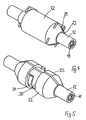
- FIG. 1 shows, two hose fittings 10 are connected by high-pressure hose lines not shown together.
- Each hose fitting 10 consists of a nipple 11 to be inserted into the inner core of a hose body, not shown, and an outer sleeve 12.
- Between nipple 11 and sleeve 12 is an annular space 13 for receiving the hose body, wherein on the outside of the nipple 11 as well as on the inside the sleeve 12 teeth 14 are formed, which dig in a compression of the sleeve 12 with the hose body in each case in the hose body and thereby establish a firm connection between the hose fitting 10 and the hose body.
- the nipple 11 has a further groove 17 for receiving a sealing ring 18 inserted therein. With this front end and the sealing ring 18 seated thereon, the two nipples 11 of the two hose fittings 10 to be connected are inserted from both sides into a centrally arranged receiving bushing 19 until the two nipples 11 abut one another at the front.
- the two sleeves 12 each have as an integral part of a radially projecting flange 20, which has a directed toward the hose fitting 10 projection 21 at its outer periphery.
- the two flange rings 20 together with an intermediate receiving bushing 19 are enclosed by two outer shells 22 placed on the outside, the half shells 22 still extending over a partial area of the respective sleeve 12 of the hose fitting 10.
- the two composite half-shells 22 form a receiving recess 23, which is adapted for fitting the flange ring 20 with projection 21 of the hose fitting 10.
- the receiving recess 23 has such an axial extent that the two flange rings 20 are axially displaceable therein by a certain amount, as will be explained.
- the two half-shells 22 each have a groove 25 for receiving the projection 21.
- FIG. 1 shows the output or mounting position of the connection and connection device in which the half-shells 22 are slipped outwardly around the two hose fittings 10 to be joined together and the receiving bushing 19 located therebetween, thereof in the in FIG. 1 shown position but can also be removed again, so that the connection of the two hose fittings is solvable.
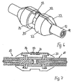
- FIG. 2 now shows a further assembly step by the two hose fittings 10 are each displaced outwards until their located on the flange rings 20 projections 21 engage in the associated grooves 25 of the half-shells 22.
- the nipples 11 move apart, and there is a gap 26 in the interior of the receiving bushing 19.
- each of the axially acting in the gap 26 pressure leads to the pressing of the respective Projection 21 in the associated groove 25 of the half-shell 22, as shown in detail in FIG. 3 is shown.
- Projection 27 and recess 28 thus together form a lock for the outer half shells 22 with the sleeve 12 and the flange ring 20 such that in the pressed-pressed position, the half-shells 22 can not be opened to the outside.
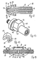
- FIG. 4 shows FIG. 4 in a first embodiment, the arrangement of U-shaped spring plugs 29, which are each guided through the two half-shells 22, that the half-shells 22 are fixed to each other.
- FIG. 5 An alternative option is in FIG. 5 shown.
- FIGS. 6 and 7 represented by the two half-shells 22 are supported by means of an outer hinge axis 32 to each other.
- spring leaves 33 can be pivotally mounted, which in turn press with bias on the half-shells 22 and set them in the closed position.
- FIG. 8 shows an embodiment, which consists of a combination of in Figures 5 or 6 and 7 illustrated embodiments.
- the half-shells 22 are in turn held together by a pre-bent spring clip 31 arranged in a recess 30, one end of the spring clip 31 being pivotably supported on a correspondingly arranged hinge axis 32.
- the hinge axis 32 is held in each case attached to the two half-shells 22 by means of welds 41 hinge straps 40.
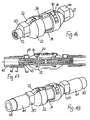
- connection and connection device can also be designed to define a mounted at the end of a high-pressure hose to be connected hose fitting 10 to a high-pressure working device, not shown.
- the receiving bushing 19 forms part of a terminal 34 of the working device, not shown, wherein the half-shells 22 engage with a formed at its axial end hook 36 in a formed on the outer periphery of the receiving bushing 19 groove 35.
- the half-shells 22 are in turn fixed axially immovable, so that they can serve as an abutment for the engagement of the flange 20 with projection 21, in particular to FIGS. 1 to 3 described.
- FIG. 10 illustrated embodiment differs from the in FIG. 9 illustrated embodiment in that the flange 20 with projection 21 is no longer located on the sleeve 12, but applied directly to the nipple 11 and fixedly connected to this, for example, is welded thereto.
- this other attachment of the flange 20 has no effect on the described function of the connection and connection device according to the invention.
- an adapter 45 which offers a connection option with its free end 47.
- the free end 47 of the adapter 45 with an external thread 46 may be formed for screwing the adapter into a connection formed on a working device.
- the adapter 45 comes in its encompassed by the half-shells 22 area at the same time the function of the receiving sleeve 19 in the previously described embodiments of the invention by the nipple 11 with the seated sealing ring 18 in the adapter 45 can be inserted.
- the front side of the adapter 45 preferably integrally the flange 20 is arranged with the engaging in the half-shells 22 projection 21, and insofar corresponds to the adapter 45 in its handling in the context of the connection and connection device to, for example FIGS. 1 to 3 described embodiment.
- a protective cap 50 It is customary to protect such hose fittings 10 at their free end prior to assembly by placing a protective cap, and in this respect includes the inventive connecting and connecting device according to FIG. 12
- a protective cap 50 This hat-shaped in a conventional manner cap 50 has, starting from its closed lid portion 52 a first protection area 51, with which the cap 50 on the nipple 11 of the hose assembly 10 can be plugged.
- the protection region 51 consists of an inside of the closed lid portion 52 projecting lug 53, which is adapted to be plugged onto the nipple 11 of the hose fitting 10.
- Axially to the protective area 21 includes a holding portion 54 which has bulged outward wall portions 55 of the protective cap 50, which are formed and arranged in a resilient embodiment so that the protective cap 50 after removal from the nipple 11 to the sleeve 12 of the hose fitting 10 attachable and thereby on the hose fitting 10 can be fixed.
- the protective cap 50 is held with the hose assembly mounted on the hose fitting 10 itself and is available in a further handling of the hose assembly 10 for a new protective function available, as from FIG. 13 seen.
- the protective cap 50 can according to the in the FIGS. 14 and 15 illustrated embodiment may be given a further function when the protective cap 50 is provided in the region of its bulged wall portions 55 with an inwardly projecting projection 56, which is assigned to a formed on the outer circumference of the sleeve 12 of the hose assembly 10 groove 57.
- the protective cap 50 When plugged onto the sleeve 12 protective cap 50, the protective cap 50 is fixed axially immovably on the hose assembly 10 upon engagement of the projection 56 in the groove 57.
- the groove 57 is arranged on the sleeve 12 in each case such that an axial displacement of the hose fitting 10 with the protective cap 50 plugged thereon is excluded toward the half shells 22.
- connection and connection device is in its entirety in FIG. 16 shown again.
- connection and connection device gives the opportunity to provide for a correspondingly simple mounting of a protective tube 60 to the connection and connection device. Due to the determination of the hose fittings 10 to be joined together by the half-shells 22, it is sufficient if the respective protective tube 60 is pushed over the sleeve 12 of each hose fitting 10, so that this sleeve 12 or the hose fitting 10 as a nipple Hose connection act.
- the outside of the sleeve 12 slid protective tube 60 is fixed to the sleeve 12 by means of an outer compression sleeve 61 which engages in a conventional manner with a frontal projection 62 in a groove 12 formed in the sleeve groove 63 and thereby fixed axially immovable.
- an internally formed toothing 64 By means of an internally formed toothing 64, the compression sleeve 61 holds the protective tube 60 firmly.
- the axial fixation of the caps 50 to be used can be used for additional securing of the connection and connection device against loosening, and for this purpose the position of the sleeve 12 mounted on the compression sleeve 61 and the width of the protective cap 50 are matched to one another in that an axial displacement of the hose fitting 10 into the half shells 22 is prevented by the protective cap 50 inserted between the half shells 22 and the compression sleeve 61.
Landscapes
- Engineering & Computer Science (AREA)
- General Engineering & Computer Science (AREA)
- Mechanical Engineering (AREA)
- Quick-Acting Or Multi-Walled Pipe Joints (AREA)
Claims (22)
- Dispositif de raccordement et de connexion pour condultes haute pression pour le raccordement d'une conduite souple à une autre conduite souple ou à un appareil de travail haute pression, l'extrémité de la conduite souple étant pourvue d'un raccord pour conduite souple (10) qui se compose d'un nipple (11) insérable dans l'âme intérieure d'un corps de conduite souple et une douille (12) placée sur le côté extérieur du corps de conduite souple, reliable au nipple et pouvant être engagée par pression sur le corps de conduite souple, le raccord pour conduite souple (10) relié au corps de conduite souple présentant un anneau de bride (20) dépassant radialement et l'extrémité dépassant du corps de conduite souple du nipple (11) présentant une garniture (18) placée sur sa périphérie extérieure et pouvant être enfichée conjointement avec la garniture (18) dans une douille de réception (19) et la douille de réception (19) et l'anneau de bride dépassant radialement (20) sont contenus par deux demi-coques (22) comportant à l'extérieur la douille de réception (19) et l'anneau de bride (20) comme dispositif de raccordement et de connexion, et un évidement (23) servant à la réception de l'anneau de bride (20) dans les demi-coques (22) étant dimensionné de telle manière qu'un déplacement axial de l'extrémité de conduite souple avec un raccord pour conduite souple (10) monté dessus entre une position de libération et une position de verrouillage formée par l'engagement à complémentarité de formes de l'anneau de bride (20) avec une forme de réception (25) réalisée côté avant sur les demi-coques (22) pour les demi-coques (22) soit permis, caractérisé en ce que les deux demi-coques (22) comportent à l'extérieur outre la douille de réception (19) et l'anneau de bride (20), une section contiguë à l'anneau de bride (20) de la douille extérieure (12).
- Dispositif de raccordement et de connexion selon la revendication 1, caractérisé en ce que l'anneau de bride (20) s'engage avec une saillie (21) dépassant axialement en direction du corps de conduite souple dans une rainure (25) réalisée côté avant dans les demi-coques (22) comme forme de réception.
- Dispositif de raccordement et de connexion selon la revendication 1, caractérisé en ce que l'anneau de bride (20) est monté sur l'extrémité côté avant de la douille (12).
- Dispositif de raccordement et de connexion selon la revendication 3, caractérisé en ce que l'anneau de bride (20) est un élément d'un seul tenant de la douille (12).
- Dispositif de raccordement et de connexion selon la revendication 1 ou 2, caractérisé en ce que l'anneau de bride (20) est monté sur une zone dépassant du corps de conduite souple du nipple (11) entre la douille (12) et la douille de réception (19).
- Dispositif de raccordement et de connexion selon l'une quelconque des revendications 1 à 5, caractérisé en ce que la douille de réception (19) présente une telle longueur que l'extrémité avant présentant la garniture (18) du nipple (11) est placée non seulement dans la position de libération mais aussi dans la position de verrouillage à l'intérieur de la douille de réception (19).
- Dispositif de raccordement et de connexion selon l'une quelconque des revendications 1 à 6, caractérisé en ce que les deux demi-coques (22) entourant la douille de réception (18) et l'anneau de bride (20) sont maintenues à l'aide d'un étrier de ressort (31) plié placé sur leur périphérie extérieure dans leur position fermée.
- Dispositif de raccordement et de connexion selon l'une quelconque des revendications 1 à 6, caractérisé en ce que les demi-coques (22) sont maintenues à l'aide de connecteurs de ressort (29) en forme de U enfichés radialement sur leurs extrémités extérieures dans leur position fermée.
- Dispositif de raccordement et de connexion selon l'une quelconque des revendications 1 à 6, caractérisé en ce que les demi-coques (22) sont maintenues à l'aide d'une charnière (32) extérieure dans leur position fermée.
- Dispositif de raccordement et de connexion selon la revendication 9, caractérisé en ce que des lames de ressort (33) reliées aux demi-coques (22) et précontraignant les demi-coques (22) respectivement dans leur position fermée sont maintenues sur l'axe (32) de la charnière.
- Dispositif de raccordement et de connexion selon la revendication 10, caractérisé en ce que la douille de réception (19) est entourée par complémentarité de formes par les demi-coques (22) et est fixée de manière immobile axialement dedans.
- Dispositif de raccordement et de connexion selon l'une quelconque des revendications 1 à 11 pour la connexion de deux conduites souples, caractérisé en ce que les demi-coques (22) entourent et maintiennent les uns sur les autres les anneaux de bride (20) des deux raccords (10) des conduites souples à relier, y compris la douille de réception (19) disposée au milleu avec les nipples (11) insérés dedans.
- Dispositif de raccordement et de connexion selon l'une quelconque des revendications 1 à 11 pour la connexion d'une conduite souple avec un appareil de travail haute pression, caractérisé en ce que la douille de réception (19) est reliée à l'appareil de travail et les demi-coques (22) sont fixées dans leur position fermée de manière immobile axialement sur la douille de réception (19) ou sur l'appareil de travail.
- Dispositif de raccordement et de connexion selon l'une quelconque des revendications 1 à 11, caractérisé en ce que la douille de réception (19) est réalisée comme un adaptateur (45) pouvant être relié à un appareil de travail ou à une conduite de tuyau présentant un raccord fileté et l'anneau de bride (20) entouré conjointement avec l'anneau de bride (20) du raccord pour conduite souple (10) par les demi-coques (22) est monté sur l'extrémité côté avant de l'adaptateur.
- Dispositif de raccordement et de connexion selon la revendication 14, caractérisé en ce qu'un filetage extérieur est monté sur l'extrémité libre (47) de l'adaptateur (45).
- Dispositif de raccordement et de connexion selon la revendication 14, caractérisé en ce qu'un filetage intérieur est réalisé sur l'extrémité libre (47) de l'adaptateur (45).
- Dispositif de raccordement et de connexion selon l'une quelconque des revendications 1 à 16, caractérisé en ce qu'un couvercle protecteur (50) maintenu de manière amovible sur le raccord pour conduite souple est prévu pour le recouvrement de l'extrémité ouverte du raccord pour conduite souple (10), et le couvercle protecteur (50) en forme de chapeau présente une zone de protection (51) pour le placement par entourage axial sur l'extrémité ouverte du raccord pour conduite souple (10) et une zone de retenue (54) contiguë axialement à la zone de protection (51) avec une zone de paroi (55) courbée vers l'extérieur pour le placement radial du couvercle protecteur (50) sur la périphérie extérieure d'une section de la douille (12) du raccord pour conduite souple (10).
- Dispositif de raccordement et de connexion selon la revendication 17, caractérisé en ce que la zone de protection (51) se compose d'une saillie (53) dépassant côté intérieur de la zone de couvercle (52) fermée pour le placement sur l'extrémité du raccord pour conduite souple (10).
- Dispositif de raccordement et de connexion selon la revendication 17 ou 18, caractérisé en ce que les zones de paroi (55) courbées vers l'extérieur du couvercle protecteur (50) sont réalisées de manière élastique.
- Dispositif de raccordement et de connexion selon l'une quelconque des revendications 17 à 19, caractérisé en ce que le couvercle protecteur (50) en forme de chapeau est fixé axialement respectivement à l'aide d'une saillie (56) s'engageant dans une rainure (57) réalisée sur le côté extérieur de la douille (12) et disposée sur le côté intérieur de ses zones de paroi (55) dans sa position placée sur le raccord pour conduite souple (10) et la rainure (57) est disposée sur la douille (12) de telle manière qu'un déplacement axial du raccord pour conduite souple (10) avec le couvercle protecteur (50) placé dessus vers les demi-coques (22) soit exclu.
- Dispositif de raccordement et de connexion selon l'une quelconque des revendications 17 à 20, caractérisé en ce qu'un tuyau de protection (60) comportant à l'extérieur la conduite haute pression avec le raccord pour conduite souple (10) raccordé à celle-ci est prévu, lequel est poussé avec son extrémité associée sur la zone dépassant des demi-coques (22) de la douille (12) du raccord pour conduite souple (10) et est fixé dessus à l'aide d'une douille de pressage (61) appliquée à l'extérieur, et en ce que la largeur du couvercle protecteur (50) et la position de la douille de pressage (81) montée sur la douille (12) sont adaptées l'une à l'autre de telle manière que le couvercle protecteur (60) puisse être Inséré entre les demi-coques (22) et la douille de pressage (61) comme des contre-appuis axiaux de sorte qu'un déplacement axial du raccord pour conduite souple (10) vers les demi-coques (22) soit exclu.
- Dispositif de raccordement et de connexion selon la revendication 21, caractérisé en ce que le tuyau de protection (60) se compose d'un matériau flexible et extensible.
Applications Claiming Priority (2)
| Application Number | Priority Date | Filing Date | Title |
|---|---|---|---|
| DE202008006612U DE202008006612U1 (de) | 2008-05-15 | 2008-05-15 | Anschluss- und Verbindungsvorrichtung für Hochdruckleitungen |
| PCT/EP2008/008953 WO2009138113A1 (fr) | 2008-05-15 | 2008-10-23 | Dispositif de raccordement et de connexion pour conduites haute pression |
Publications (3)
| Publication Number | Publication Date |
|---|---|
| EP2276960A1 EP2276960A1 (fr) | 2011-01-26 |
| EP2276960B1 true EP2276960B1 (fr) | 2013-06-05 |
| EP2276960B8 EP2276960B8 (fr) | 2013-07-10 |
Family
ID=39678433
Family Applications (1)
| Application Number | Title | Priority Date | Filing Date |
|---|---|---|---|
| EP08846210.6A Active EP2276960B8 (fr) | 2008-05-15 | 2008-10-23 | Dispositif de raccordement et de connexion pour conduites haute pression |
Country Status (7)
| Country | Link |
|---|---|
| US (1) | US7938457B2 (fr) |
| EP (1) | EP2276960B8 (fr) |
| DE (1) | DE202008006612U1 (fr) |
| DK (1) | DK2276960T3 (fr) |
| ES (1) | ES2426221T3 (fr) |
| PT (1) | PT2276960E (fr) |
| WO (1) | WO2009138113A1 (fr) |
Cited By (1)
| Publication number | Priority date | Publication date | Assignee | Title |
|---|---|---|---|---|
| WO2015028590A1 (fr) | 2013-08-29 | 2015-03-05 | Christoph Nickel | Élément de liaison de segments de flexibles et de tuyaux |
Families Citing this family (10)
| Publication number | Priority date | Publication date | Assignee | Title |
|---|---|---|---|---|
| DE202009010333U1 (de) | 2009-06-10 | 2010-02-25 | Parker Hannifin Gmbh & Co. Kg | Hochdruckschlauchanordnung mit Funktionsüberwachung |
| MD264Z (ro) * | 2009-07-31 | 2011-03-31 | Ион РАССОХИН | Procedeu de îmbinare a niplului cu furtunul |
| DE202011051325U1 (de) | 2011-09-16 | 2011-12-01 | Parker Hannifin Manufacturing Germany GmbH & Co. KG | Unter Druck drehbare Anschluss- und Verbindungsvorrichtung für Hochdruckleitungen |
| US9518690B2 (en) * | 2014-09-23 | 2016-12-13 | Dominique Bélisle | Fire hose girdle |
| US10302241B2 (en) | 2014-10-30 | 2019-05-28 | Somero Enterprises, Inc. | Protective shield for concrete hose joints |
| CN105299378B (zh) * | 2015-11-27 | 2017-12-22 | 江苏省绿岛管阀件有限公司 | 一种管道 |
| CN105299357B (zh) * | 2015-11-27 | 2017-12-22 | 江苏省绿岛管阀件有限公司 | 一种可调节的管道连接组件 |
| CN106195473A (zh) * | 2016-08-29 | 2016-12-07 | 南通爱慕希机械股份有限公司 | 一种高压管接头 |
| CN110670286A (zh) * | 2019-08-21 | 2020-01-10 | 海宁市创兴经编有限公司 | 面料热定型整理装置中壳体的连接机构 |
| CN112696790B (zh) * | 2020-12-23 | 2022-04-15 | 安徽郁金香新能源科技有限公司 | 末端系统减少水阻集成安装方法 |
Family Cites Families (33)
| Publication number | Priority date | Publication date | Assignee | Title |
|---|---|---|---|---|
| US1043806A (en) * | 1909-05-18 | 1912-11-12 | American Bridge Company | Hose-coupling. |
| US1985012A (en) * | 1933-08-12 | 1934-12-18 | Lincoln Eng Co | Swivel |
| US2383010A (en) * | 1943-08-25 | 1945-08-21 | Albert W Miller | Detachable coupling |
| US2837351A (en) * | 1954-02-01 | 1958-06-03 | Cardox Corp | Electrically insulated pipe coupling with confined pressure-sealing means |
| US3041088A (en) * | 1959-06-18 | 1962-06-26 | Jr Ira M Brandon | Coupling assembly |
| US3195931A (en) * | 1963-03-18 | 1965-07-20 | Space Technology And Res Corp | Symmetrical hose coupling |
| DE2310680C2 (de) * | 1973-03-03 | 1975-04-10 | Karl 4040 Neuss Weinhold | Vorrichtung zum Verbinden zweier AnschluBstUcke für Schlauch- oder Rohrenden |
| GB1461606A (en) * | 1973-03-30 | 1977-01-13 | Jonsson N G | Couplings |
| US4236736A (en) * | 1978-05-01 | 1980-12-02 | Turnbuckle Products Corporation | Hose coupling |
| US4473369A (en) * | 1982-01-11 | 1984-09-25 | Baxter Travenol Laboratories, Inc. | Continuous ambulatory peritoneal dialysis clamping system |
| US4432759A (en) * | 1982-04-26 | 1984-02-21 | Abbott Laboratories | Connecting device for medical liquid containers |
| US4669760A (en) * | 1986-02-05 | 1987-06-02 | Flow Industries, Inc. | Swivel fitting arrangement for use in a pressurized fluid line |
| US4741559A (en) * | 1987-05-28 | 1988-05-03 | Berghman Earle E | Coupling protector |
| DE3921443A1 (de) * | 1989-06-30 | 1991-01-10 | Weinhold Karl | Schlauchfassung |
| US5269572A (en) * | 1992-08-28 | 1993-12-14 | Gold Star Manufacturing, Inc. | Apparatus and method for coupling elongated members |
| US5454603A (en) * | 1993-10-22 | 1995-10-03 | Staley, Jr.; Colin R. | Co-axial hose coupling adapted for replacing inner hose upon rupture thereof and method therefor |
| DE19513058C2 (de) * | 1995-04-07 | 1997-02-13 | Ford Werke Ag | Rohrverbindung |
| US5853200A (en) * | 1996-04-15 | 1998-12-29 | Gary A. Zieres | Hose coupling boot |
| DE19642338C1 (de) | 1996-10-14 | 1998-07-16 | Prange Karl Heinz | Verbindungselement zum Verbinden von Schlauch- und Rohrleitungsabschnitten |
| US5895076A (en) * | 1996-11-04 | 1999-04-20 | Tyler J. Elliot | Hose coupling shroud |
| GB9801261D0 (en) * | 1998-01-21 | 1998-03-18 | Peters Joseph L | Couplings for medical cannulae |
| DE19939161C1 (de) * | 1999-08-20 | 2001-06-21 | Waluga Armaturen | Verbindungselement zum Verbinden zweier Schlauch- und/oder Rohrleitungsenden |
| DE19940147C2 (de) * | 1999-08-24 | 2001-08-16 | Karl Weinhold | Vorrichtung für die Verbindung zweier Schlauchenden |
| GB0004212D0 (en) * | 2000-02-23 | 2000-04-12 | Plexus Ocean Syst Ltd | Pipe joint |
| US6565129B2 (en) * | 2001-06-21 | 2003-05-20 | Halliburton Energy Services, Inc. | Quick connect system and method for fluid devices |
| US6913294B2 (en) * | 2002-11-14 | 2005-07-05 | Halla Climate Control Canada, Inc. | Coupling for coaxial connection of fluid conduits |
| US20040227347A1 (en) * | 2003-05-12 | 2004-11-18 | Fundin Robert Lyle | Adaptable water diverting fixture |
| DE202004002063U1 (de) * | 2004-02-11 | 2004-04-22 | Prange, Karl-Heinz | Verbindungselement zum Verbinden von Schlauch- und Rohrleitungsabschnitten |
| WO2006002459A1 (fr) | 2004-07-02 | 2006-01-12 | Australasian Steel Products Pty Ltd | Équipement de sécurité de tuyau |
| US7537245B2 (en) * | 2005-02-14 | 2009-05-26 | Medtronic, Inc. | Strain relief device and connector assemblies incorporating same |
| EP1726865B1 (fr) * | 2005-05-27 | 2010-02-24 | NORMA Germany GmbH | Ensemble de raccordement de sections terminales de deux conduits de fluide à connecter |
| DE202006007315U1 (de) | 2006-03-14 | 2006-07-20 | Falch Hochdruckstrahlsysteme Gmbh | Verschraubung von Hochdruckleitungen |
| DE202006015598U1 (de) | 2006-10-11 | 2006-12-28 | Parker Hannifin Gmbh & Co. Kg | Kurzbauende Schlaucharmatur |
-
2008
- 2008-05-15 DE DE202008006612U patent/DE202008006612U1/de not_active Expired - Lifetime
- 2008-10-23 PT PT88462106T patent/PT2276960E/pt unknown
- 2008-10-23 DK DK08846210.6T patent/DK2276960T3/da active
- 2008-10-23 EP EP08846210.6A patent/EP2276960B8/fr active Active
- 2008-10-23 WO PCT/EP2008/008953 patent/WO2009138113A1/fr not_active Ceased
- 2008-10-23 ES ES08846210T patent/ES2426221T3/es active Active
-
2009
- 2009-10-12 US US12/577,435 patent/US7938457B2/en active Active
Cited By (2)
| Publication number | Priority date | Publication date | Assignee | Title |
|---|---|---|---|---|
| WO2015028590A1 (fr) | 2013-08-29 | 2015-03-05 | Christoph Nickel | Élément de liaison de segments de flexibles et de tuyaux |
| DE102013109403A1 (de) | 2013-08-29 | 2015-03-05 | Christoph Nickel | Verbindungselement zum Verbinden von Schlauch- und Rohrleitungsabschnitten |
Also Published As
| Publication number | Publication date |
|---|---|
| ES2426221T3 (es) | 2013-10-22 |
| WO2009138113A1 (fr) | 2009-11-19 |
| DK2276960T3 (da) | 2013-09-08 |
| PT2276960E (pt) | 2013-09-05 |
| EP2276960A1 (fr) | 2011-01-26 |
| EP2276960B8 (fr) | 2013-07-10 |
| DE202008006612U1 (de) | 2008-08-07 |
| US20100059991A1 (en) | 2010-03-11 |
| US7938457B2 (en) | 2011-05-10 |
Similar Documents
| Publication | Publication Date | Title |
|---|---|---|
| EP2276960B1 (fr) | Dispositif de raccordement et de connexion pour conduites haute pression | |
| EP0728979A1 (fr) | Raccord étanche entre un tuyau en matière plastique et une pièce de raccordement fabriquée en métal | |
| EP3084153B1 (fr) | Dispositif de réglage d'arbre à cames, moteur à combustion et procédé de montage | |
| DE102011008084A1 (de) | Hochdruckfeste Verbindungsvorrichtung für Rohr- oder Schlauchleitungen mit Bajonettverschluss | |
| DE102014109418B4 (de) | WC-Sitzgelenk und WC-Sitzgarnitur | |
| WO2021190897A1 (fr) | Raccord de type enfichable ayant un verrouillage de préassemblage | |
| WO2009007165A1 (fr) | Tuyau d'air de charge | |
| DE202008005929U1 (de) | Anschlussvorrichtung für Medienleitungen im Bereich einer Wandungsdurchführung sowie Wandungselement | |
| EP3397889B1 (fr) | Dispositif de raccordement | |
| EP1931903A1 (fr) | Conduite a tube ondule | |
| DE102008063582A1 (de) | Rohrschelle | |
| DE202011004777U1 (de) | Steckverbindung für Fluidleitungen | |
| DE4223250A1 (de) | Automatisch montierbare Steckkupplung für Leitungsschläuche in Kraftfahrzeugen | |
| DE102008061132B4 (de) | System aus Anbohrarmatur und Bohrloch-Dichthülse | |
| DE60305641T2 (de) | Verbindungsvorrichtung zur ende-zu-ende-verbindung von zwei rohren | |
| EP3138703B1 (fr) | Systeme de controle de pression de pneu pour un vehicule automobile | |
| WO2018091478A1 (fr) | Système de raccordement pour conduites acheminant un fluide | |
| DE102013109403A1 (de) | Verbindungselement zum Verbinden von Schlauch- und Rohrleitungsabschnitten | |
| DE202005020263U1 (de) | Mehrfachkupplung für Medienleitungen | |
| DE102015000490A1 (de) | Befestigungselement | |
| DE102012220516A1 (de) | Montagehilfe | |
| DE202011051325U1 (de) | Unter Druck drehbare Anschluss- und Verbindungsvorrichtung für Hochdruckleitungen | |
| DE20204723U1 (de) | Positionsadapter für Rohr- und Kabelverbindungen | |
| DE202012003242U1 (de) | Brandschutzvorrichtung bei Übergang auf Kunststoffrohr | |
| DE102009053759A1 (de) | Montageschlüssel, Montagevorrichtung und Montageset zum Montieren und Demontieren von Injektorkomponenten und Injektoren in Injektorgehäusen sowie entsprechende Verfahren |
Legal Events
| Date | Code | Title | Description |
|---|---|---|---|
| PUAI | Public reference made under article 153(3) epc to a published international application that has entered the european phase |
Free format text: ORIGINAL CODE: 0009012 |
|
| 17P | Request for examination filed |
Effective date: 20090429 |
|
| AK | Designated contracting states |
Kind code of ref document: A1 Designated state(s): AT BE BG CH CY CZ DE DK EE ES FI FR GB GR HR HU IE IS IT LI LT LU LV MC MT NL NO PL PT RO SE SI SK TR |
|
| AX | Request for extension of the european patent |
Extension state: AL BA MK RS |
|
| RIN1 | Information on inventor provided before grant (corrected) |
Inventor name: LEVIN, MAXIM Inventor name: WEINHANDL, FRANZ |
|
| DAX | Request for extension of the european patent (deleted) | ||
| GRAP | Despatch of communication of intention to grant a patent |
Free format text: ORIGINAL CODE: EPIDOSNIGR1 |
|
| GRAS | Grant fee paid |
Free format text: ORIGINAL CODE: EPIDOSNIGR3 |
|
| GRAA | (expected) grant |
Free format text: ORIGINAL CODE: 0009210 |
|
| AK | Designated contracting states |
Kind code of ref document: B1 Designated state(s): AT BE BG CH CY CZ DE DK EE ES FI FR GB GR HR HU IE IS IT LI LT LU LV MC MT NL NO PL PT RO SE SI SK TR |
|
| REG | Reference to a national code |
Ref country code: GB Ref legal event code: FG4D Free format text: NOT ENGLISH |
|
| REG | Reference to a national code |
Ref country code: CH Ref legal event code: EP |
|
| REG | Reference to a national code |
Ref country code: AT Ref legal event code: REF Ref document number: 615871 Country of ref document: AT Kind code of ref document: T Effective date: 20130615 |
|
| RAP2 | Party data changed (patent owner data changed or rights of a patent transferred) |
Owner name: PARKER HANNIFIN MANUFACTURING GERMANY GMBH & CO. K |
|
| REG | Reference to a national code |
Ref country code: IE Ref legal event code: FG4D Free format text: LANGUAGE OF EP DOCUMENT: GERMAN |
|
| REG | Reference to a national code |
Ref country code: DE Ref legal event code: R096 Ref document number: 502008010085 Country of ref document: DE Effective date: 20130801 |
|
| REG | Reference to a national code |
Ref country code: AT Ref legal event code: HC Ref document number: 615871 Country of ref document: AT Kind code of ref document: T Owner name: PARKER HANNIFIN MANUFACTURING GERMANY GMBH & C, DE Effective date: 20130709 |
|
| REG | Reference to a national code |
Ref country code: PT Ref legal event code: SC4A Free format text: AVAILABILITY OF NATIONAL TRANSLATION Effective date: 20130829 |
|
| REG | Reference to a national code |
Ref country code: DK Ref legal event code: T3 |
|
| REG | Reference to a national code |
Ref country code: NL Ref legal event code: T3 |
|
| REG | Reference to a national code |
Ref country code: ES Ref legal event code: FG2A Ref document number: 2426221 Country of ref document: ES Kind code of ref document: T3 Effective date: 20131022 |
|
| PG25 | Lapsed in a contracting state [announced via postgrant information from national office to epo] |
Ref country code: SE Free format text: LAPSE BECAUSE OF FAILURE TO SUBMIT A TRANSLATION OF THE DESCRIPTION OR TO PAY THE FEE WITHIN THE PRESCRIBED TIME-LIMIT Effective date: 20130605 Ref country code: SI Free format text: LAPSE BECAUSE OF FAILURE TO SUBMIT A TRANSLATION OF THE DESCRIPTION OR TO PAY THE FEE WITHIN THE PRESCRIBED TIME-LIMIT Effective date: 20130605 Ref country code: NO Free format text: LAPSE BECAUSE OF FAILURE TO SUBMIT A TRANSLATION OF THE DESCRIPTION OR TO PAY THE FEE WITHIN THE PRESCRIBED TIME-LIMIT Effective date: 20130905 Ref country code: LT Free format text: LAPSE BECAUSE OF FAILURE TO SUBMIT A TRANSLATION OF THE DESCRIPTION OR TO PAY THE FEE WITHIN THE PRESCRIBED TIME-LIMIT Effective date: 20130605 Ref country code: FI Free format text: LAPSE BECAUSE OF FAILURE TO SUBMIT A TRANSLATION OF THE DESCRIPTION OR TO PAY THE FEE WITHIN THE PRESCRIBED TIME-LIMIT Effective date: 20130605 Ref country code: GR Free format text: LAPSE BECAUSE OF FAILURE TO SUBMIT A TRANSLATION OF THE DESCRIPTION OR TO PAY THE FEE WITHIN THE PRESCRIBED TIME-LIMIT Effective date: 20130906 |
|
| REG | Reference to a national code |
Ref country code: LT Ref legal event code: MG4D |
|
| PG25 | Lapsed in a contracting state [announced via postgrant information from national office to epo] |
Ref country code: BG Free format text: LAPSE BECAUSE OF FAILURE TO SUBMIT A TRANSLATION OF THE DESCRIPTION OR TO PAY THE FEE WITHIN THE PRESCRIBED TIME-LIMIT Effective date: 20130905 Ref country code: HR Free format text: LAPSE BECAUSE OF FAILURE TO SUBMIT A TRANSLATION OF THE DESCRIPTION OR TO PAY THE FEE WITHIN THE PRESCRIBED TIME-LIMIT Effective date: 20130605 Ref country code: PL Free format text: LAPSE BECAUSE OF FAILURE TO SUBMIT A TRANSLATION OF THE DESCRIPTION OR TO PAY THE FEE WITHIN THE PRESCRIBED TIME-LIMIT Effective date: 20130605 |
|
| PG25 | Lapsed in a contracting state [announced via postgrant information from national office to epo] |
Ref country code: LV Free format text: LAPSE BECAUSE OF FAILURE TO SUBMIT A TRANSLATION OF THE DESCRIPTION OR TO PAY THE FEE WITHIN THE PRESCRIBED TIME-LIMIT Effective date: 20130605 |
|
| PG25 | Lapsed in a contracting state [announced via postgrant information from national office to epo] |
Ref country code: IS Free format text: LAPSE BECAUSE OF FAILURE TO SUBMIT A TRANSLATION OF THE DESCRIPTION OR TO PAY THE FEE WITHIN THE PRESCRIBED TIME-LIMIT Effective date: 20131005 Ref country code: EE Free format text: LAPSE BECAUSE OF FAILURE TO SUBMIT A TRANSLATION OF THE DESCRIPTION OR TO PAY THE FEE WITHIN THE PRESCRIBED TIME-LIMIT Effective date: 20130605 Ref country code: SK Free format text: LAPSE BECAUSE OF FAILURE TO SUBMIT A TRANSLATION OF THE DESCRIPTION OR TO PAY THE FEE WITHIN THE PRESCRIBED TIME-LIMIT Effective date: 20130605 Ref country code: CZ Free format text: LAPSE BECAUSE OF FAILURE TO SUBMIT A TRANSLATION OF THE DESCRIPTION OR TO PAY THE FEE WITHIN THE PRESCRIBED TIME-LIMIT Effective date: 20130605 |
|
| PG25 | Lapsed in a contracting state [announced via postgrant information from national office to epo] |
Ref country code: RO Free format text: LAPSE BECAUSE OF FAILURE TO SUBMIT A TRANSLATION OF THE DESCRIPTION OR TO PAY THE FEE WITHIN THE PRESCRIBED TIME-LIMIT Effective date: 20130605 |
|
| PLBE | No opposition filed within time limit |
Free format text: ORIGINAL CODE: 0009261 |
|
| STAA | Information on the status of an ep patent application or granted ep patent |
Free format text: STATUS: NO OPPOSITION FILED WITHIN TIME LIMIT |
|
| BERE | Be: lapsed |
Owner name: PARKER HANNIFIN MANUFACTURING GERMANY G.M.B.H. & C Effective date: 20131031 |
|
| 26N | No opposition filed |
Effective date: 20140306 |
|
| PG25 | Lapsed in a contracting state [announced via postgrant information from national office to epo] |
Ref country code: MC Free format text: LAPSE BECAUSE OF FAILURE TO SUBMIT A TRANSLATION OF THE DESCRIPTION OR TO PAY THE FEE WITHIN THE PRESCRIBED TIME-LIMIT Effective date: 20130605 |
|
| REG | Reference to a national code |
Ref country code: DE Ref legal event code: R097 Ref document number: 502008010085 Country of ref document: DE Effective date: 20140306 |
|
| PG25 | Lapsed in a contracting state [announced via postgrant information from national office to epo] |
Ref country code: BE Free format text: LAPSE BECAUSE OF NON-PAYMENT OF DUE FEES Effective date: 20131031 |
|
| PG25 | Lapsed in a contracting state [announced via postgrant information from national office to epo] |
Ref country code: CY Free format text: LAPSE BECAUSE OF FAILURE TO SUBMIT A TRANSLATION OF THE DESCRIPTION OR TO PAY THE FEE WITHIN THE PRESCRIBED TIME-LIMIT Effective date: 20130605 |
|
| PG25 | Lapsed in a contracting state [announced via postgrant information from national office to epo] |
Ref country code: HU Free format text: LAPSE BECAUSE OF FAILURE TO SUBMIT A TRANSLATION OF THE DESCRIPTION OR TO PAY THE FEE WITHIN THE PRESCRIBED TIME-LIMIT; INVALID AB INITIO Effective date: 20081023 |
|
| PG25 | Lapsed in a contracting state [announced via postgrant information from national office to epo] |
Ref country code: MT Free format text: LAPSE BECAUSE OF FAILURE TO SUBMIT A TRANSLATION OF THE DESCRIPTION OR TO PAY THE FEE WITHIN THE PRESCRIBED TIME-LIMIT Effective date: 20130605 |
|
| REG | Reference to a national code |
Ref country code: FR Ref legal event code: PLFP Year of fee payment: 8 |
|
| REG | Reference to a national code |
Ref country code: FR Ref legal event code: PLFP Year of fee payment: 9 |
|
| REG | Reference to a national code |
Ref country code: FR Ref legal event code: PLFP Year of fee payment: 10 |
|
| REG | Reference to a national code |
Ref country code: FR Ref legal event code: PLFP Year of fee payment: 11 |
|
| P01 | Opt-out of the competence of the unified patent court (upc) registered |
Effective date: 20230524 |
|
| REG | Reference to a national code |
Ref country code: CH Ref legal event code: U11 Free format text: ST27 STATUS EVENT CODE: U-0-0-U10-U11 (AS PROVIDED BY THE NATIONAL OFFICE) Effective date: 20251101 |
|
| PGFP | Annual fee paid to national office [announced via postgrant information from national office to epo] |
Ref country code: LU Payment date: 20251027 Year of fee payment: 18 Ref country code: NL Payment date: 20251026 Year of fee payment: 18 |
|
| PGFP | Annual fee paid to national office [announced via postgrant information from national office to epo] |
Ref country code: PT Payment date: 20251006 Year of fee payment: 18 |
|
| PGFP | Annual fee paid to national office [announced via postgrant information from national office to epo] |
Ref country code: DE Payment date: 20251029 Year of fee payment: 18 |
|
| PGFP | Annual fee paid to national office [announced via postgrant information from national office to epo] |
Ref country code: GB Payment date: 20251027 Year of fee payment: 18 |
|
| PGFP | Annual fee paid to national office [announced via postgrant information from national office to epo] |
Ref country code: AT Payment date: 20251029 Year of fee payment: 18 |
|
| REG | Reference to a national code |
Ref country code: DE Ref legal event code: R082 Ref document number: 502008010085 Country of ref document: DE Representative=s name: DIPAS PATENTANWALTS GMBH, DE |
|
| PGFP | Annual fee paid to national office [announced via postgrant information from national office to epo] |
Ref country code: IT Payment date: 20251021 Year of fee payment: 18 Ref country code: DK Payment date: 20251027 Year of fee payment: 18 |
|
| PGFP | Annual fee paid to national office [announced via postgrant information from national office to epo] |
Ref country code: FR Payment date: 20251027 Year of fee payment: 18 |
|
| PGFP | Annual fee paid to national office [announced via postgrant information from national office to epo] |
Ref country code: TR Payment date: 20251007 Year of fee payment: 18 |
|
| PGFP | Annual fee paid to national office [announced via postgrant information from national office to epo] |
Ref country code: CH Payment date: 20251101 Year of fee payment: 18 |
|
| PGFP | Annual fee paid to national office [announced via postgrant information from national office to epo] |
Ref country code: IE Payment date: 20251027 Year of fee payment: 18 |
|
| PGFP | Annual fee paid to national office [announced via postgrant information from national office to epo] |
Ref country code: ES Payment date: 20251103 Year of fee payment: 18 |