EP2277016B1 - Verfahren und einrichtung zur bestimmung einer durchflussmessgrösse eines fluides - Google Patents
Verfahren und einrichtung zur bestimmung einer durchflussmessgrösse eines fluides Download PDFInfo
- Publication number
- EP2277016B1 EP2277016B1 EP09761904.3A EP09761904A EP2277016B1 EP 2277016 B1 EP2277016 B1 EP 2277016B1 EP 09761904 A EP09761904 A EP 09761904A EP 2277016 B1 EP2277016 B1 EP 2277016B1
- Authority
- EP
- European Patent Office
- Prior art keywords
- flow
- fluid
- solvent
- chamber
- plugs
- Prior art date
- Legal status (The legal status is an assumption and is not a legal conclusion. Google has not performed a legal analysis and makes no representation as to the accuracy of the status listed.)
- Not-in-force
Links
- 239000012530 fluid Substances 0.000 claims description 46
- 238000000034 method Methods 0.000 claims description 29
- 230000035699 permeability Effects 0.000 claims description 14
- 239000002904 solvent Substances 0.000 claims description 13
- 239000000463 material Substances 0.000 claims description 12
- 239000000203 mixture Substances 0.000 claims description 4
- 238000012546 transfer Methods 0.000 claims description 3
- 238000013016 damping Methods 0.000 claims 1
- 229930195733 hydrocarbon Natural products 0.000 description 25
- 150000002430 hydrocarbons Chemical class 0.000 description 25
- 239000004215 Carbon black (E152) Substances 0.000 description 24
- 239000012071 phase Substances 0.000 description 15
- 238000006073 displacement reaction Methods 0.000 description 7
- PEDCQBHIVMGVHV-UHFFFAOYSA-N Glycerine Chemical compound OCC(O)CO PEDCQBHIVMGVHV-UHFFFAOYSA-N 0.000 description 6
- 238000009434 installation Methods 0.000 description 5
- 230000008859 change Effects 0.000 description 4
- 238000005259 measurement Methods 0.000 description 3
- OKTJSMMVPCPJKN-UHFFFAOYSA-N Carbon Chemical compound [C] OKTJSMMVPCPJKN-UHFFFAOYSA-N 0.000 description 2
- 239000004952 Polyamide Substances 0.000 description 2
- 239000012080 ambient air Substances 0.000 description 2
- 239000000470 constituent Substances 0.000 description 2
- 238000009792 diffusion process Methods 0.000 description 2
- 239000007789 gas Substances 0.000 description 2
- 229920002647 polyamide Polymers 0.000 description 2
- 238000012545 processing Methods 0.000 description 2
- 230000001105 regulatory effect Effects 0.000 description 2
- 238000012216 screening Methods 0.000 description 2
- 230000035945 sensitivity Effects 0.000 description 2
- 229920002545 silicone oil Polymers 0.000 description 2
- 238000012360 testing method Methods 0.000 description 2
- 230000001052 transient effect Effects 0.000 description 2
- 230000007704 transition Effects 0.000 description 2
- XLYOFNOQVPJJNP-UHFFFAOYSA-N water Substances O XLYOFNOQVPJJNP-UHFFFAOYSA-N 0.000 description 2
- LFQSCWFLJHTTHZ-UHFFFAOYSA-N Ethanol Chemical compound CCO LFQSCWFLJHTTHZ-UHFFFAOYSA-N 0.000 description 1
- 230000008901 benefit Effects 0.000 description 1
- 238000004891 communication Methods 0.000 description 1
- 230000001419 dependent effect Effects 0.000 description 1
- 239000002828 fuel tank Substances 0.000 description 1
- 239000007792 gaseous phase Substances 0.000 description 1
- 239000007788 liquid Substances 0.000 description 1
- 238000004519 manufacturing process Methods 0.000 description 1
- 239000002184 metal Substances 0.000 description 1
- 238000012986 modification Methods 0.000 description 1
- 230000004048 modification Effects 0.000 description 1
- 229920000642 polymer Polymers 0.000 description 1
- 239000004810 polytetrafluoroethylene Substances 0.000 description 1
- 229920001343 polytetrafluoroethylene Polymers 0.000 description 1
- 230000008569 process Effects 0.000 description 1
- 239000007790 solid phase Substances 0.000 description 1
- 229910001220 stainless steel Inorganic materials 0.000 description 1
- 239000010935 stainless steel Substances 0.000 description 1
- 238000010561 standard procedure Methods 0.000 description 1
- 238000002910 structure generation Methods 0.000 description 1
- 229920001169 thermoplastic Polymers 0.000 description 1
- 238000011144 upstream manufacturing Methods 0.000 description 1
Images


Classifications
-
- G—PHYSICS
- G01—MEASURING; TESTING
- G01F—MEASURING VOLUME, VOLUME FLOW, MASS FLOW OR LIQUID LEVEL; METERING BY VOLUME
- G01F1/00—Measuring the volume flow or mass flow of fluid or fluent solid material wherein the fluid passes through a meter in a continuous flow
- G01F1/704—Measuring the volume flow or mass flow of fluid or fluent solid material wherein the fluid passes through a meter in a continuous flow using marked regions or existing inhomogeneities within the fluid stream, e.g. statistically occurring variations in a fluid parameter
- G01F1/708—Measuring the time taken to traverse a fixed distance
- G01F1/7086—Measuring the time taken to traverse a fixed distance using optical detecting arrangements
-
- G—PHYSICS
- G01—MEASURING; TESTING
- G01F—MEASURING VOLUME, VOLUME FLOW, MASS FLOW OR LIQUID LEVEL; METERING BY VOLUME
- G01F1/00—Measuring the volume flow or mass flow of fluid or fluent solid material wherein the fluid passes through a meter in a continuous flow
- G01F1/74—Devices for measuring flow of a fluid or flow of a fluent solid material in suspension in another fluid
-
- G—PHYSICS
- G01—MEASURING; TESTING
- G01N—INVESTIGATING OR ANALYSING MATERIALS BY DETERMINING THEIR CHEMICAL OR PHYSICAL PROPERTIES
- G01N15/00—Investigating characteristics of particles; Investigating permeability, pore-volume or surface-area of porous materials
- G01N15/10—Investigating individual particles
- G01N2015/1027—Determining speed or velocity of a particle
Definitions
- the present invention relates to a method for determining the flow rate of a fluid, and an installation for carrying out this method.
- US-A-4,210,809 provides an example of a method of the type defined by the preamble of appended claim 1.
- the determination method according to the invention provides access to many types of information relating to the flow of liquids or gases. This determination method makes it possible in particular to deduce information relating to the transport of a solvent through the walls of an enclosure.
- the invention proposes in particular to study the permeability of containers, in which are received hydrocarbons.
- the storage and transport of these pose problems, which are precisely related to the permeability of thermoplastic polymers, used for the manufacture of storage and transport structures.
- the invention aims to remedy these various disadvantages.
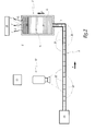
- the facility for determining a fluid flow comprises a flow member 6, for example made in the form of a flexible tube, in particular PTFE.
- This tube 6 is advantageously translucent, in particular transparent, in order to cooperate with a camera system, which is in this case a camera 10.
- This camera which is directed towards this flow tube 6, is associated with IT means 11, allowing the processing of the data generated by this camera.
- the internal section of the flow member 6 is between 10 -4 mm 2 and 1 mm 2 , preferably between 10 -3 and 10 -1 mm 2 .
- This inner section refers to a dimension, which excludes the walls of the flow member 6.
- the flow member 6 opens into an enclosure 2, which can be made in one piece, or be formed of several different elements.
- the chamber 2 comprises a body 2 1 , made of a non-permeable material such as a metal. This body 2 1 delimits a window 2 2 , in which can be received an insert 2 3 , made of a material which it is desired to measure for example the permeability.
- V is the internal volume of the chamber 2
- P the walls of the insert 2 3
- E outdoor ambient air.
- the seal between the inlet 4 of the enclosure 2, and the tube 6, is provided by any appropriate means.
- This member 14 which is of known type, is placed upstream of the 6.
- an analysis apparatus 15 disposed in the vicinity of the insert 23 .
- This apparatus 15, which is for example a gas chromatograph, makes it possible to analyze the gaseous phase escaping from the chamber 2, as will be seen in more detail in the following.
- this chamber is occupied by a buffer fluid T, so that the entire interior volume of the chamber is occupied by fluid.
- the buffer fluid T is advantageous, insofar as this makes it possible to prevent, on the one hand, the hydrocarbon leakage towards the tube 6 and, on the other hand, the mixing between the hydrocarbon studied and the fluid flowing in the tube 6, as will be seen in what follows.
- plugs 20 are fluid or even solid phases flowing along the tube 6, occupying substantially the width of the latter. These plugs are separated from each other by a carrier fluid, which is immiscible with the constituent fluid plugs.
- plugs may be formed, in a manner known per se, in means of conventional structure generation, which are distinct from the tube 6. Then, when these plugs are formed, they are injected into the tube 6, by any appropriate means. Alternatively, these plugs can be formed directly in the tube 6 by any suitable conventional procedure.
- plugs of the same nature or of different natures are, for example, drops formed by a mixture of colored water and glycerol, while the carrier phase is for example formed by a silicone oil.
- the distinction between these drops and these carrier phase segments is operated by the camera 10, in particular by contrast.
- the drops or the carrier phase may be dark, while the carrier phase or the drops may be clear, so that the respective volumes of the drops and sections are visible. It is also possible that the drops and sections are transparent, but their interface remains visible by the camera.
- L the length of the different drops, and L 'the length of the various intermediate sections.
- these lengths L and L ' are less than the value of the field of the camera, in particular less than 5 cm, typically between 0.1 and 1 mm.
- the different drops have the same length L, while the different sections have the same length L '.
- the drops and / or the sections have different lengths between them.
- the use of the buffer fluid T makes it possible to prevent the plugs 20 from entering the internal volume V, when this buffer fluid occupies part of the tube 6 as illustrated in this figure 2 . This is advantageous, since these plugs can then be reused easily, for a next procedure.
- the speed of displacement of the plugs 20 inside the tube 6 is measured, thanks to the camera 10 associated with the computer processing means 11. Also knowing the section of this tube, it is possible to deduce the flow fluid volume, formed by plugs 20 and sections 22, moved per unit of time within this tube. This value corresponds to the change in hydrocarbon volume inside the chamber 2.
- the figure 3 illustrates the variation, as a function of time t, of the volume V of the flow fluid, formed by plugs 20 and sections 22, which has moved in tube 6 in order to compensate for the exit of hydrocarbon H. note that these curves are first decomposed into a first transient type zone, denoted 1, having a relatively large slope, and a second zone II of permanent type, lower slope.
- Zone I corresponds to the initial phase of hydrocarbon escape, out of the internal volume V, namely that for which this hydrocarbon diffuses and stabilizes in the thickness of the walls P of the insert 23 .
- This zone I is representative of the advance of the front of propagation of the hydrocarbon, inside the walls P.
- zone II is relative to a posterior phase, during which the hydrocarbon migrates towards outside E.
- This zone II corresponds to a steady state, for which the diffusion and the solubility of the hydrocarbon is balance, thus defining the permeability of the material with respect to the hydrocarbon.
- This figure 3 thus allows access to information relating to the transport of the hydrocarbon, through the insert 2 3 .
- This generic term of transport comprises, on the one hand, the transfer of this hydrocarbon towards the inside of the walls, materialized by the zone I is, on the other hand, the actual permeability of these walls with respect to the hydrocarbon, which is materialized by zone II.
- the curve of the figure 3 may have a substantially horizontal zone II, as illustrated in dashed lines. This means that, in this case, there is only transfer of the hydrocarbon to the walls P. On the other hand, this hydrocarbon does not diffuse towards the ambient air.
- the solvent studied is formed by a mixture of different components.
- the apparatus 15 makes it possible to carry out at least one analysis of the gaseous fraction discharged from the chamber 2 via the insert 23 .
- such an analysis makes it possible to identify whether one or other of the components of this solvent tends to escape before or after the other component (s).
- figure 3 highlights one advantage of the invention, namely the fact that it allows access to more information, than in the prior art.
- figure 4 illustrates a curve, obtained by the implementation of gravimetric measurements according to the state of the art. It will be recalled that this method makes it possible to study only the loss of mass of the assembly, formed by the container and the contents.
- this figure 4 illustrates the variation as a function of time, not of the volume V as in the case of the invention, but of the mass M.
- the corresponding curve comprises a zone I ', coinciding with the abscissa axis, then a zone II' , of the same slope as that II of the figure 3 .
- the transition between, on the one hand, the zones I and II, on the other hand, the zones I 'and II' operates on either side of the same transition time, noted t 0 .
- the diffusion phase of the hydrocarbon in the thickness of the insert 23 is not identified in the prior art, since this phenomenon does not induce any loss of mass of the assembly formed by the container and the contents.
- the flow member not in the form of an isolated tube, but in the form of a channel formed in a wafer.
- This channel is then produced according to the standard procedures of the state of the art, which are described in particular in DC Duffy, JC MacDonald, Olivier JA Schueller, M. Whitesides Gorge, Anal. Chem., 70, p 4974-4984, 1998 .
- the downstream end of the channel then opens at the entrance of the enclosure 2, via any appropriate means.
- a flow rate, related to the output of a fluid was measured outside the interior volume of the chamber. It is also possible to measure, in accordance with the invention, a flow rate related to a fluid inlet in this interior volume. In this case, this phenomenon induces a displacement of the plugs 20 and sections 22, no longer on the right as on the figure 2 but on the left. Similarly, the speed of displacement of the plugs is measured, which makes it possible to access information relating to the increase of the volume of fluid in the chamber.
- a fluid flow rate has been measured in order to deduce information relating to the permeability of the chamber.
- the operating conditions in particular the temperature and / or the pressure and / or the humidity, are varied so as to obtain a modification of the value of the internal volume of the enclosure.
- the fluid initially admitted into this chamber has a constant density
- the expansion of the chamber leads to an arrival of plugs 20 towards its internal volume, since the volume of the fluid is invariant. Measuring the flow of these plugs, thus set in motion, provides access to the corresponding value of expansion of the enclosure.
- the camera 10 is associated with a single flow tube 6.
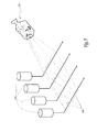
- a same camera 110 can visualize the displacement of plugs inside several tubes. 106, themselves in communication with a plurality of enclosures 102, as illustrated in FIG. figure 5 .
- a single camera allows to implement, simultaneously, several measures of volume variation.
- the invention achieves the previously mentioned objectives.
- the invention makes it possible to determine, in a simple and economical way, the volume variation of a fluid.
- this implementation can be done automatically, as well as continuously.
- the process according to the invention is of great sensitivity, because the use of a reduced section flow member makes it possible to detect very low flow rate values, which may be less than one nanolitre per hour.
- the invention provides access to a lot of information, in particular relating to the transient phase of exhaust of a fluid outside a chamber.
- An enclosure 2 is used, whose body 2 1 is made of stainless steel.
- the window 2 2 of this chamber 2 is sealed by means of an insert 23 made of polyamide.
- the internal volume of the chamber 2 is 2 ml.
- the whole of this enclosure, except for the connection zones, is filled with an alcohol to which the polyamide is permeable.
- a flow tube 6 made of PFA.
- This tube has a length of 2 meters, and an inner diameter of 250 micrometers. It is associated with an electropneumatic pressure regulator 14, in accordance with that marketed by SMC under the reference ITV0010.
- Drops formed by a mixture of water, glycerol and a dye are generated, which are separated by a succession of carrier phase sections formed of a silicone oil.
- the respective lengths L and L ', of each drop and of each section, are close to 0.5 mm.
- the volume variation of the fluid inside the chamber is then measured, while maintaining the operating conditions at the same time. a temperature of 40 ° C and a pressure of 300 mbar.
- zones I and II of the figure 2 access is made to zones I and II of the figure 2 . It is found that after 1 hour, 0.2 ml of fluid have diffused since the interior volume towards the walls of the enclosure. Then, after this initial phase, this fluid migrates outwards, which corresponds to zone II of the figure 2 . After 24 hours, the total measured volume change is 1 ml.
Landscapes
- Physics & Mathematics (AREA)
- Fluid Mechanics (AREA)
- General Physics & Mathematics (AREA)
- Measuring Volume Flow (AREA)
Claims (12)
- Verfahren zur Ermittlung wenigstens eines Durchflussstromwerts von wenigstens einem Fluid, bei welchem man dieses Fluid, Strömungsfluid genannt, in ein Durchströmungselement (6) einbringt, welches mit dem Innenvolumen (V) eines abgeschlossenen Raums (2) in Verbindung steht und in Form einer Aufeinanderfolge von Stopfen (20), die von Teilstücken (22) eines Trägerstrangs separiert sind, ausgebildet ist, man die Verlagerungsgeschwindigkeit dieser Stopfen in dem Durchströmungselement misst, und man daraus den oder jeden Durchflussstromwert des Strömungsfluids (20, 22) ableitet, dadurch gekennzeichnet, dass man ein Lösungsmittel (H) in wenigstens einen Teil des Innenvolumens (V) des abgeschlossenen Raums (2) einbringt und man ausgehend von dem Durchflussstromwert des Strömungsfluids (20, 22) Informationen ableitet bezüglich der Bewegung des Lösungsmittels durch wenigstens einen Teil (23) von Wänden (P) des abgeschlossenen Raums hindurch.
- Verfahren gemäß Anspruch 1, dadurch gekennzeichnet, dass man einen abgeschlossenen Raum (2) verwendet, der aufweist einen Körper (21), durch welchen hindurch das Lösungsmittel sich nicht bewegt, sowie einen Einsatz (23), der geeignet ist an dem Körper (22) angebracht zu werden, insbesondere auf lösbare Weise, wobei der Einsatz aus einem Material gemacht ist, durch welches hindurch sich das Lösungsmittel bewegen kann, wobei das Material insbesondere für das Lösungsmittel durchlässig ist.
- Verfahren gemäß einem der Ansprüche 1 oder 2, dadurch gekennzeichnet, dass man den abgeschlossenen Raum (2) auf eine Temperatur und einen Druck einstellt, die im Wesentlichen konstant sind.
- Verfahren gemäß einem der vorhergehenden Ansprüche, dadurch gekennzeichnet, dass man ausgehend von dem Durchflussstrom eine Variation des Volumens des Strömungsfluids in Abhängigkeit von der Zeit ableitet.
- Verfahren gemäß Anspruch 4, dadurch gekennzeichnet, dass man eine Übergangszone (1) identifiziert, die zu dem Lösungsmittelmaterietransfer zu dem Inneren der Wände (P) des besagten Teils (23) des abgeschlossenen Raums korrespondiert.
- Verfahren gemäß Anspruch 4 oder 5, dadurch gekennzeichnet, dass man eine Permanentzone (11) identifiziert, die zur eigentlichen Permeabilität dieser Wände (P) bezüglich des Lösungsmittels korrespondiert.
- Verfahren gemäß einem der vorhergehenden Ansprüche, dadurch gekennzeichnet, dass man das Lösungsmittel (H) bezüglich des Strömungsfluids (20, 22) separiert mittels eines Propfenfluids (T).
- Verfahren gemäß einem der vorhergehenden Ansprüche, dadurch gekennzeichnet, dass das Lösungsmittel (H) gebildet ist von einer Mischung von Bestandteilen und man wenigstens eine Gasfraktionsanalyse durchführt, die ausgeht von der Bewegung dieses Lösungsmittels durch den besagten Teil (23) der Wände (P) des abgeschlossenen Raums hindurch.
- Verfahren gemäß einem der vorhergehenden Ansprüche, dadurch gekennzeichnet, dass man die Verlagerungsgeschwindigkeit der Stopfen (20) misst mittels eines Digitalbildaufnahmesystems , insbesondere einer Kamera (10).
- Verfahren gemäß Anspruch 9, dadurch gekennzeichnet, dass man mehrere Durchströmungselemente (106) verwendet, die sich wenigstens teilweise parallel zueinander erstrecken, man unterschiedliche Strömungsfluide in diese unterschiedlichen Durchströmungselemente einbringt, und man die Verlagerungsgeschwindigkeit der Stopfen jedes Durchströmungsfluids mittels eines einzigen Bildaufnahmesystems (110) misst.
- Verfahren gemäß Anspruch 9 oder 10, dadurch gekennzeichnet, dass man den Durchflussstromwert ableitet durch Verwenden der Gleichung:Q = V.S.F; wobeiQ dem Durchflussstromwert entspricht;V der Pixelvariation pro Zeiteinheit entspricht, die dem Bildaufnahmesystem zugeordnet ist;S dem Innenquerschnitt des Durchströmungselement (6) entspricht; undF der Vergrößerung des Bildaufnahmesystems entspricht.
- Verfahren gemäß einem der vorhergehenden Ansprüche, dadurch gekennzeichnet, dass der Innenquerschnitt des Durchströmungselements (6) zwischen 10-4 mm2 und 1 mm2, bevorzugt zwischen 10-3 und 10-1 mm2 beträgt.
Applications Claiming Priority (2)
| Application Number | Priority Date | Filing Date | Title |
|---|---|---|---|
| FR0853175A FR2931232B1 (fr) | 2008-05-16 | 2008-05-16 | Procede et installation de determination d'une valeur de debit d'un fluide |
| PCT/FR2009/050910 WO2009150353A2 (fr) | 2008-05-16 | 2009-05-15 | Procede et installation de determination d'une valeur de debit d'un fluide |
Publications (2)
| Publication Number | Publication Date |
|---|---|
| EP2277016A2 EP2277016A2 (de) | 2011-01-26 |
| EP2277016B1 true EP2277016B1 (de) | 2013-09-11 |
Family
ID=40316941
Family Applications (1)
| Application Number | Title | Priority Date | Filing Date |
|---|---|---|---|
| EP09761904.3A Not-in-force EP2277016B1 (de) | 2008-05-16 | 2009-05-15 | Verfahren und einrichtung zur bestimmung einer durchflussmessgrösse eines fluides |
Country Status (6)
| Country | Link |
|---|---|
| US (1) | US20110178734A1 (de) |
| EP (1) | EP2277016B1 (de) |
| JP (1) | JP5296194B2 (de) |
| CN (1) | CN102027335B (de) |
| FR (1) | FR2931232B1 (de) |
| WO (1) | WO2009150353A2 (de) |
Families Citing this family (3)
| Publication number | Priority date | Publication date | Assignee | Title |
|---|---|---|---|---|
| US8871062B2 (en) * | 2010-11-23 | 2014-10-28 | Charles David Gilliam | Falling film evaporator |
| CN105181049B (zh) * | 2015-08-26 | 2018-07-31 | 北京市计量检测科学研究院 | 管道内流体流量的测量方法、测量系统及辅助测量系统 |
| CN111505173B (zh) * | 2020-06-12 | 2020-12-08 | 赛默飞世尔(上海)仪器有限公司 | 确定液流流量的方法、馏分收集器及液相色谱系统 |
Family Cites Families (11)
| Publication number | Priority date | Publication date | Assignee | Title |
|---|---|---|---|---|
| US4203317A (en) * | 1978-06-20 | 1980-05-20 | Gupta Krishna M | Porosimeter |
| US4210809A (en) * | 1979-03-16 | 1980-07-01 | Technicon Instruments Corporation | Method and apparatus for the non-invasive determination of the characteristics of a segmented fluid stream |
| JPS5713316A (en) * | 1980-06-28 | 1982-01-23 | Denshi Kagaku Kk | Method and device for measurement of sample flowing at low speed |
| JPS59171815A (ja) * | 1983-03-18 | 1984-09-28 | Jeol Ltd | 流量計 |
| JPS61175547A (ja) * | 1985-01-30 | 1986-08-07 | Nippon Felt Kk | 加圧通水量試験装置 |
| JPH02287120A (ja) * | 1989-04-27 | 1990-11-27 | Mitsubishi Heavy Ind Ltd | 色素式流量計測装置 |
| JPH0933302A (ja) * | 1995-07-22 | 1997-02-07 | Tokyo Gas Co Ltd | 垂直濡れ壁における散水状態測定方法 |
| JPH11173887A (ja) * | 1997-12-11 | 1999-07-02 | Tokimec Inc | 流速計測装置及び流量計測装置 |
| JP4120576B2 (ja) * | 2003-12-15 | 2008-07-16 | 株式会社デンソー | 液量測定装置 |
| US7918244B2 (en) * | 2005-05-02 | 2011-04-05 | Massachusetts Institute Of Technology | Microfluidic bubble logic devices |
| CN100480641C (zh) * | 2007-07-17 | 2009-04-22 | 浙江大学 | 一种管道流量测量装置 |
-
2008
- 2008-05-16 FR FR0853175A patent/FR2931232B1/fr not_active Expired - Fee Related
-
2009
- 2009-05-15 EP EP09761904.3A patent/EP2277016B1/de not_active Not-in-force
- 2009-05-15 US US12/992,641 patent/US20110178734A1/en not_active Abandoned
- 2009-05-15 WO PCT/FR2009/050910 patent/WO2009150353A2/fr not_active Ceased
- 2009-05-15 JP JP2011508989A patent/JP5296194B2/ja not_active Expired - Fee Related
- 2009-05-15 CN CN200980117726.0A patent/CN102027335B/zh not_active Expired - Fee Related
Also Published As
| Publication number | Publication date |
|---|---|
| FR2931232A1 (fr) | 2009-11-20 |
| US20110178734A1 (en) | 2011-07-21 |
| WO2009150353A2 (fr) | 2009-12-17 |
| EP2277016A2 (de) | 2011-01-26 |
| CN102027335B (zh) | 2013-05-15 |
| FR2931232B1 (fr) | 2010-05-28 |
| CN102027335A (zh) | 2011-04-20 |
| WO2009150353A3 (fr) | 2010-03-18 |
| JP2011521221A (ja) | 2011-07-21 |
| JP5296194B2 (ja) | 2013-09-25 |
Similar Documents
| Publication | Publication Date | Title |
|---|---|---|
| EP1821093B1 (de) | Verfahren und Vorrichtung zur Permeationsmessung | |
| EP2682736B1 (de) | Verfahren und Vorrichtung zur Durchlässigkeitsmessung | |
| EP3385696B1 (de) | Vorrichtung und verfahren zur bestimmung der grösse einer leckage | |
| WO2008080987A1 (fr) | Dispositif et procede de mesures couplees permettant un suivi global et en continu de traces de goudrons presentes dans un flux gazeux | |
| EP1877755A1 (de) | Verfahren und vorrichtung zur bewertung des flusses und elektrischer parameter eines porösen mediums | |
| EP3023766B1 (de) | Verfahren und vorrichtung zur durchlässigkeitsmessung mit massenspektrometrie | |
| EP2277016A2 (de) | Verfahren und einrichtung zur bestimmung einer durchflussmessgrösse eines fluides | |
| EP4698884A1 (de) | System zur entnahme von gas aus einem festen porösen medium | |
| EP3812745B1 (de) | Vorrichtung zur messung der stabilität eines brennstoffs mithilfe von messungen der änderung der thermischen kapazität und fluoreszenz | |
| FR2818746A1 (fr) | Procede et dispositif d'evaluation de l'indice de wobbe d'un gaz combustible | |
| FR2522820A1 (fr) | Procede de mesure des fuites de recipients contenant un gaz sous pression, notamment un gaz de petrole liquefie, et installation pour sa mise en oeuvre | |
| WO2001035067A2 (fr) | Methode et dispositif de determination du seuil de depot des fractions lourdes contenues dans un fluide hydrocarbone liquide | |
| EP1880190B1 (de) | Verfahren zur messung der durchlässigkeit für gase mit schneller konditionierung und einrichtung zur durchführung dieses verfahrens | |
| EP3682233A1 (de) | Vorrichtung zur messung der oxidationsstabilität und/oder der thermischen stabilität eines brennstoffs mithilfe eines mikrofluidischen chips | |
| CA2351832C (fr) | Dispositif de transport pour analyser des constituants hydrocarbones | |
| EP2856144B1 (de) | Vorrichtung zur flüssigkeitsanalyse mit einem brennbaren medium sowie entsprechendes verfahren | |
| EP3901604B1 (de) | Symstem und verfahren zur überwachung von gaslecks mithilfe einer optischen messung | |
| EP1930712A1 (de) | Vorrichtung zur Bestimmung der Eigenschaften einer Zweiphasenströmung und Einsatzverfahren einer solchen Vorrichtung | |
| WO2021254710A1 (fr) | Procede pour determiner le volume poreux d'un echantillon de milieu poreux | |
| EP3935468B1 (de) | Mikrofluidischer generator zur erzeugung eines gasgemisches | |
| FR2959314A1 (fr) | Diagnostic in-situ des proprietes barrieres d'un module photovoltaique | |
| EP3850185B1 (de) | Verfahren zur bestimmung des freien volumens eines ringraumes eines flexiblen rohres und zugehöriges system | |
| FR3147865A1 (fr) | Procédé et système de détection d’une inversion d’écoulement de gaz dans un circuit de gaz de turbomachine | |
| FR2873812A1 (fr) | Dispositif de prelevement de composes volatils | |
| FR3000208A1 (fr) | Dispositif et procede de test d'un echantillon, en particulier de mise sous contrainte d'un echantillon |
Legal Events
| Date | Code | Title | Description |
|---|---|---|---|
| PUAI | Public reference made under article 153(3) epc to a published international application that has entered the european phase |
Free format text: ORIGINAL CODE: 0009012 |
|
| 17P | Request for examination filed |
Effective date: 20101105 |
|
| AK | Designated contracting states |
Kind code of ref document: A2 Designated state(s): AT BE BG CH CY CZ DE DK EE ES FI FR GB GR HR HU IE IS IT LI LT LU LV MC MK MT NL NO PL PT RO SE SI SK TR |
|
| AX | Request for extension of the european patent |
Extension state: AL BA RS |
|
| RIN1 | Information on inventor provided before grant (corrected) |
Inventor name: CLERICO, THOMAS Inventor name: GUIRARDEL, MATTHIEU |
|
| DAX | Request for extension of the european patent (deleted) | ||
| 17Q | First examination report despatched |
Effective date: 20120723 |
|
| GRAP | Despatch of communication of intention to grant a patent |
Free format text: ORIGINAL CODE: EPIDOSNIGR1 |
|
| INTG | Intention to grant announced |
Effective date: 20130506 |
|
| GRAS | Grant fee paid |
Free format text: ORIGINAL CODE: EPIDOSNIGR3 |
|
| GRAA | (expected) grant |
Free format text: ORIGINAL CODE: 0009210 |
|
| AK | Designated contracting states |
Kind code of ref document: B1 Designated state(s): AT BE BG CH CY CZ DE DK EE ES FI FR GB GR HR HU IE IS IT LI LT LU LV MC MK MT NL NO PL PT RO SE SI SK TR |
|
| REG | Reference to a national code |
Ref country code: GB Ref legal event code: FG4D Free format text: NOT ENGLISH |
|
| REG | Reference to a national code |
Ref country code: CH Ref legal event code: EP |
|
| REG | Reference to a national code |
Ref country code: AT Ref legal event code: REF Ref document number: 631896 Country of ref document: AT Kind code of ref document: T Effective date: 20130915 |
|
| REG | Reference to a national code |
Ref country code: IE Ref legal event code: FG4D Free format text: LANGUAGE OF EP DOCUMENT: FRENCH |
|
| REG | Reference to a national code |
Ref country code: DE Ref legal event code: R096 Ref document number: 602009018744 Country of ref document: DE Effective date: 20131107 |
|
| PG25 | Lapsed in a contracting state [announced via postgrant information from national office to epo] |
Ref country code: LT Free format text: LAPSE BECAUSE OF FAILURE TO SUBMIT A TRANSLATION OF THE DESCRIPTION OR TO PAY THE FEE WITHIN THE PRESCRIBED TIME-LIMIT Effective date: 20130911 Ref country code: SE Free format text: LAPSE BECAUSE OF FAILURE TO SUBMIT A TRANSLATION OF THE DESCRIPTION OR TO PAY THE FEE WITHIN THE PRESCRIBED TIME-LIMIT Effective date: 20130911 Ref country code: CY Free format text: LAPSE BECAUSE OF FAILURE TO SUBMIT A TRANSLATION OF THE DESCRIPTION OR TO PAY THE FEE WITHIN THE PRESCRIBED TIME-LIMIT Effective date: 20130918 Ref country code: NO Free format text: LAPSE BECAUSE OF FAILURE TO SUBMIT A TRANSLATION OF THE DESCRIPTION OR TO PAY THE FEE WITHIN THE PRESCRIBED TIME-LIMIT Effective date: 20131211 Ref country code: HR Free format text: LAPSE BECAUSE OF FAILURE TO SUBMIT A TRANSLATION OF THE DESCRIPTION OR TO PAY THE FEE WITHIN THE PRESCRIBED TIME-LIMIT Effective date: 20130911 |
|
| REG | Reference to a national code |
Ref country code: NL Ref legal event code: VDEP Effective date: 20130911 |
|
| REG | Reference to a national code |
Ref country code: AT Ref legal event code: MK05 Ref document number: 631896 Country of ref document: AT Kind code of ref document: T Effective date: 20130911 |
|
| REG | Reference to a national code |
Ref country code: LT Ref legal event code: MG4D |
|
| PG25 | Lapsed in a contracting state [announced via postgrant information from national office to epo] |
Ref country code: SI Free format text: LAPSE BECAUSE OF FAILURE TO SUBMIT A TRANSLATION OF THE DESCRIPTION OR TO PAY THE FEE WITHIN THE PRESCRIBED TIME-LIMIT Effective date: 20130911 Ref country code: GR Free format text: LAPSE BECAUSE OF FAILURE TO SUBMIT A TRANSLATION OF THE DESCRIPTION OR TO PAY THE FEE WITHIN THE PRESCRIBED TIME-LIMIT Effective date: 20131212 Ref country code: LV Free format text: LAPSE BECAUSE OF FAILURE TO SUBMIT A TRANSLATION OF THE DESCRIPTION OR TO PAY THE FEE WITHIN THE PRESCRIBED TIME-LIMIT Effective date: 20130911 Ref country code: FI Free format text: LAPSE BECAUSE OF FAILURE TO SUBMIT A TRANSLATION OF THE DESCRIPTION OR TO PAY THE FEE WITHIN THE PRESCRIBED TIME-LIMIT Effective date: 20130911 |
|
| PG25 | Lapsed in a contracting state [announced via postgrant information from national office to epo] |
Ref country code: CY Free format text: LAPSE BECAUSE OF FAILURE TO SUBMIT A TRANSLATION OF THE DESCRIPTION OR TO PAY THE FEE WITHIN THE PRESCRIBED TIME-LIMIT Effective date: 20130911 |
|
| PG25 | Lapsed in a contracting state [announced via postgrant information from national office to epo] |
Ref country code: IS Free format text: LAPSE BECAUSE OF FAILURE TO SUBMIT A TRANSLATION OF THE DESCRIPTION OR TO PAY THE FEE WITHIN THE PRESCRIBED TIME-LIMIT Effective date: 20140111 Ref country code: CZ Free format text: LAPSE BECAUSE OF FAILURE TO SUBMIT A TRANSLATION OF THE DESCRIPTION OR TO PAY THE FEE WITHIN THE PRESCRIBED TIME-LIMIT Effective date: 20130911 Ref country code: NL Free format text: LAPSE BECAUSE OF FAILURE TO SUBMIT A TRANSLATION OF THE DESCRIPTION OR TO PAY THE FEE WITHIN THE PRESCRIBED TIME-LIMIT Effective date: 20130911 Ref country code: RO Free format text: LAPSE BECAUSE OF FAILURE TO SUBMIT A TRANSLATION OF THE DESCRIPTION OR TO PAY THE FEE WITHIN THE PRESCRIBED TIME-LIMIT Effective date: 20130911 Ref country code: SK Free format text: LAPSE BECAUSE OF FAILURE TO SUBMIT A TRANSLATION OF THE DESCRIPTION OR TO PAY THE FEE WITHIN THE PRESCRIBED TIME-LIMIT Effective date: 20130911 Ref country code: EE Free format text: LAPSE BECAUSE OF FAILURE TO SUBMIT A TRANSLATION OF THE DESCRIPTION OR TO PAY THE FEE WITHIN THE PRESCRIBED TIME-LIMIT Effective date: 20130911 |
|
| PG25 | Lapsed in a contracting state [announced via postgrant information from national office to epo] |
Ref country code: AT Free format text: LAPSE BECAUSE OF FAILURE TO SUBMIT A TRANSLATION OF THE DESCRIPTION OR TO PAY THE FEE WITHIN THE PRESCRIBED TIME-LIMIT Effective date: 20130911 Ref country code: ES Free format text: LAPSE BECAUSE OF FAILURE TO SUBMIT A TRANSLATION OF THE DESCRIPTION OR TO PAY THE FEE WITHIN THE PRESCRIBED TIME-LIMIT Effective date: 20130911 Ref country code: PL Free format text: LAPSE BECAUSE OF FAILURE TO SUBMIT A TRANSLATION OF THE DESCRIPTION OR TO PAY THE FEE WITHIN THE PRESCRIBED TIME-LIMIT Effective date: 20130911 |
|
| REG | Reference to a national code |
Ref country code: DE Ref legal event code: R097 Ref document number: 602009018744 Country of ref document: DE |
|
| PG25 | Lapsed in a contracting state [announced via postgrant information from national office to epo] |
Ref country code: PT Free format text: LAPSE BECAUSE OF FAILURE TO SUBMIT A TRANSLATION OF THE DESCRIPTION OR TO PAY THE FEE WITHIN THE PRESCRIBED TIME-LIMIT Effective date: 20140113 |
|
| PLBE | No opposition filed within time limit |
Free format text: ORIGINAL CODE: 0009261 |
|
| STAA | Information on the status of an ep patent application or granted ep patent |
Free format text: STATUS: NO OPPOSITION FILED WITHIN TIME LIMIT |
|
| 26N | No opposition filed |
Effective date: 20140612 |
|
| PG25 | Lapsed in a contracting state [announced via postgrant information from national office to epo] |
Ref country code: IT Free format text: LAPSE BECAUSE OF FAILURE TO SUBMIT A TRANSLATION OF THE DESCRIPTION OR TO PAY THE FEE WITHIN THE PRESCRIBED TIME-LIMIT Effective date: 20130911 |
|
| REG | Reference to a national code |
Ref country code: DE Ref legal event code: R097 Ref document number: 602009018744 Country of ref document: DE Effective date: 20140612 |
|
| PG25 | Lapsed in a contracting state [announced via postgrant information from national office to epo] |
Ref country code: DK Free format text: LAPSE BECAUSE OF FAILURE TO SUBMIT A TRANSLATION OF THE DESCRIPTION OR TO PAY THE FEE WITHIN THE PRESCRIBED TIME-LIMIT Effective date: 20130911 |
|
| REG | Reference to a national code |
Ref country code: DE Ref legal event code: R119 Ref document number: 602009018744 Country of ref document: DE |
|
| PG25 | Lapsed in a contracting state [announced via postgrant information from national office to epo] |
Ref country code: LU Free format text: LAPSE BECAUSE OF FAILURE TO SUBMIT A TRANSLATION OF THE DESCRIPTION OR TO PAY THE FEE WITHIN THE PRESCRIBED TIME-LIMIT Effective date: 20140515 |
|
| REG | Reference to a national code |
Ref country code: CH Ref legal event code: PL |
|
| GBPC | Gb: european patent ceased through non-payment of renewal fee |
Effective date: 20140515 |
|
| PG25 | Lapsed in a contracting state [announced via postgrant information from national office to epo] |
Ref country code: MC Free format text: LAPSE BECAUSE OF FAILURE TO SUBMIT A TRANSLATION OF THE DESCRIPTION OR TO PAY THE FEE WITHIN THE PRESCRIBED TIME-LIMIT Effective date: 20130911 Ref country code: CH Free format text: LAPSE BECAUSE OF NON-PAYMENT OF DUE FEES Effective date: 20140531 Ref country code: LI Free format text: LAPSE BECAUSE OF NON-PAYMENT OF DUE FEES Effective date: 20140531 |
|
| REG | Reference to a national code |
Ref country code: IE Ref legal event code: MM4A |
|
| REG | Reference to a national code |
Ref country code: DE Ref legal event code: R119 Ref document number: 602009018744 Country of ref document: DE Effective date: 20141202 |
|
| REG | Reference to a national code |
Ref country code: FR Ref legal event code: ST Effective date: 20150130 |
|
| PG25 | Lapsed in a contracting state [announced via postgrant information from national office to epo] |
Ref country code: IE Free format text: LAPSE BECAUSE OF NON-PAYMENT OF DUE FEES Effective date: 20140515 Ref country code: DE Free format text: LAPSE BECAUSE OF NON-PAYMENT OF DUE FEES Effective date: 20141202 |
|
| PG25 | Lapsed in a contracting state [announced via postgrant information from national office to epo] |
Ref country code: FR Free format text: LAPSE BECAUSE OF NON-PAYMENT OF DUE FEES Effective date: 20140602 Ref country code: GB Free format text: LAPSE BECAUSE OF NON-PAYMENT OF DUE FEES Effective date: 20140515 |
|
| PG25 | Lapsed in a contracting state [announced via postgrant information from national office to epo] |
Ref country code: MT Free format text: LAPSE BECAUSE OF FAILURE TO SUBMIT A TRANSLATION OF THE DESCRIPTION OR TO PAY THE FEE WITHIN THE PRESCRIBED TIME-LIMIT Effective date: 20130911 |
|
| PG25 | Lapsed in a contracting state [announced via postgrant information from national office to epo] |
Ref country code: BG Free format text: LAPSE BECAUSE OF FAILURE TO SUBMIT A TRANSLATION OF THE DESCRIPTION OR TO PAY THE FEE WITHIN THE PRESCRIBED TIME-LIMIT Effective date: 20130911 |
|
| PG25 | Lapsed in a contracting state [announced via postgrant information from national office to epo] |
Ref country code: HU Free format text: LAPSE BECAUSE OF FAILURE TO SUBMIT A TRANSLATION OF THE DESCRIPTION OR TO PAY THE FEE WITHIN THE PRESCRIBED TIME-LIMIT; INVALID AB INITIO Effective date: 20090515 Ref country code: TR Free format text: LAPSE BECAUSE OF FAILURE TO SUBMIT A TRANSLATION OF THE DESCRIPTION OR TO PAY THE FEE WITHIN THE PRESCRIBED TIME-LIMIT Effective date: 20130911 Ref country code: BE Free format text: LAPSE BECAUSE OF FAILURE TO SUBMIT A TRANSLATION OF THE DESCRIPTION OR TO PAY THE FEE WITHIN THE PRESCRIBED TIME-LIMIT Effective date: 20140531 |
|
| PG25 | Lapsed in a contracting state [announced via postgrant information from national office to epo] |
Ref country code: MK Free format text: LAPSE BECAUSE OF FAILURE TO SUBMIT A TRANSLATION OF THE DESCRIPTION OR TO PAY THE FEE WITHIN THE PRESCRIBED TIME-LIMIT Effective date: 20130911 |