EP2277033B1 - Vorrichtung zur messung der elektrischen eigenschaften fester oder flüssiger geologischer proben - Google Patents
Vorrichtung zur messung der elektrischen eigenschaften fester oder flüssiger geologischer proben Download PDFInfo
- Publication number
- EP2277033B1 EP2277033B1 EP09745574.5A EP09745574A EP2277033B1 EP 2277033 B1 EP2277033 B1 EP 2277033B1 EP 09745574 A EP09745574 A EP 09745574A EP 2277033 B1 EP2277033 B1 EP 2277033B1
- Authority
- EP
- European Patent Office
- Prior art keywords
- measuring device
- electric properties
- electrode
- geological samples
- samples according
- Prior art date
- Legal status (The legal status is an assumption and is not a legal conclusion. Google has not performed a legal analysis and makes no representation as to the accuracy of the status listed.)
- Active
Links
Images


Classifications
-
- G—PHYSICS
- G01—MEASURING; TESTING
- G01N—INVESTIGATING OR ANALYSING MATERIALS BY DETERMINING THEIR CHEMICAL OR PHYSICAL PROPERTIES
- G01N27/00—Investigating or analysing materials by the use of electric, electrochemical, or magnetic means
- G01N27/02—Investigating or analysing materials by the use of electric, electrochemical, or magnetic means by investigating impedance
- G01N27/04—Investigating or analysing materials by the use of electric, electrochemical, or magnetic means by investigating impedance by investigating resistance
- G01N27/041—Investigating or analysing materials by the use of electric, electrochemical, or magnetic means by investigating impedance by investigating resistance of a solid body
-
- G—PHYSICS
- G01—MEASURING; TESTING
- G01N—INVESTIGATING OR ANALYSING MATERIALS BY DETERMINING THEIR CHEMICAL OR PHYSICAL PROPERTIES
- G01N27/00—Investigating or analysing materials by the use of electric, electrochemical, or magnetic means
- G01N27/02—Investigating or analysing materials by the use of electric, electrochemical, or magnetic means by investigating impedance
- G01N27/04—Investigating or analysing materials by the use of electric, electrochemical, or magnetic means by investigating impedance by investigating resistance
- G01N27/06—Investigating or analysing materials by the use of electric, electrochemical, or magnetic means by investigating impedance by investigating resistance of a liquid
- G01N27/07—Construction of measuring vessels; Electrodes therefor
-
- G—PHYSICS
- G01—MEASURING; TESTING
- G01N—INVESTIGATING OR ANALYSING MATERIALS BY DETERMINING THEIR CHEMICAL OR PHYSICAL PROPERTIES
- G01N33/00—Investigating or analysing materials by specific methods not covered by groups G01N1/00 - G01N31/00
- G01N33/24—Earth materials
Definitions
- the present invention relates to a measuring device of the electric properties of liquid or solid geological samples, such as rocks, preferably from gas or oil reservoirs and saturation fluids of the same.
- the measurement of the low-frequency complex impedance, i.e. lower than 100kHz, of rock samples from gas or oil reservoirs is normally effected through two complementary measurement techniques, with two or four electrode, respectively.
- an electric contact is established between each electrode and a surface portion of the sample, an alternating electric current is injected and the potential difference which is established between the same electrodes, is measured.
- the most common configuration used for cylindrical samples is that of a capacitor whose parallel and flat plates are in contact with the faces of said sample.
- the complex impedance of the capacitor thus filled, or its admittance is measured when the frequency varies, through an impedance analyzer, which calculates the ratio between the potential difference at the electrodes and the current injected.
- the dielectric spectrum ⁇ ( ⁇ ) of the sample is obtained from the complex impedance Z( ⁇ ) measured.
- a thin layer of mineral oil with insulating or slightly conductive characteristics may be present on the rock surface or a part of the water may evaporate, totally or partially drying the surface of the sample. This creates a contact impedance and a potential drop through the layer, with a consequent over-estimation of the resistance of the substrate of the sample, also called bulk resistance.
- a reduction in the contact impedance does not solve all the problems linked with the two-electrode measurement devices.
- electrode polarization effects in particular in low-frequency dielectric measurements on rocks with a high saturation and/or saturated by brine containing high concentrations of ionic carriers, can be particularly significant.
- DE 4414619 A1 discloses a method and an apparatus for measuring physico-chemical properties of moistened granular mixtures comprising two-half shells defining a sample area and a plurality of electrodes arranged on the opposite ends and on the lateral surface of the sample.
- GB 2322942 A discloses a device for taking electrical resistiuity measurements on a solid sample by means of a plurality of electrodes arranged on the lateral surface of the sample and clamped thereto.
- a measurement device which is capable of using both the two-electrode and four-electrode techniques, with the same cell and at frequencies ranging from 10 Hz to 10 MHz.
- This device includes two flat electrodes in contact with the sample faces to inject current and two rings as measurement electrodes of the voltage positioned on the lateral surface of the sample and suitably spaced from each other along the cylinder axis and in a symmetrical position with respect to the centre of the cylinder.
- An objective of the present invention is to overcome the above drawbacks and, in particular, to provide a measuring device of the electric properties of geological samples which offers the possibility of applying two- and four-electrode techniques in a rapid sequence and with sufficient accuracy.
- Another objective of the present invention is to provide a measuring device of the electric properties of geological samples which, when used for effecting two-electrode measurements, is not subjected to systemic errors or to over-estimation of the substrate resistance.
- a further objective of the present invention is to provide a measuring device of the electric properties of geological samples which, when used to effect four-electrode measurements, offers accurate measurements even when effected at high frequency.
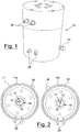
- a preferred and non-limiting embodiment is shown of a device for the measurement of the electric properties of geological samples, indicated as a whole with 10.
- the measuring device 10 comprises a hollow body, preferably cylindrical, consisting of two half-shells 11,12 one coaxially sliding over the other, partially overlapping in correspondence with a portion 11a,12a having a reduced thickness.
- a pair of coplanar contacts is advantageously situated on each base of the half-shells 11,12.
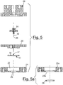
- Each pair of coplanar contacts comprises a first electrode for the injection of the current, having a substantially flat shape and provided with a pass-through hole 17, in correspondence with which a second electrode is arranged for measuring the voltage (13).
- the first injection electrodes of the current are preferably circular in shape and the pass-through hole 17 is positioned in the centre of the same. Furthermore, in a preferred embodiment, the first electrodes 14 are made of gold-plated brass.
- the sheet 15 is advantageously extremely plastic and deforms by adhering to the surface of the geological sample subjected to measurement, when a sufficiently high pressure is exerted on the electrode 14. This sheet 15 also protects the first electrode 14 from corrosion due to the brine.
- first elastic means 30 such as, for example, compression springs, preferably uniformly distributed.
- the springs 30 are made of harmonic steel wire with a diameter of 1.25 mm and have a diameter of 9.25 mm, a free length of 22.0 mm and a minimum operative length of 10.5 mm (useful coils 5.5).
- the constant of these springs 30 is preferably 8.92 N/mm.
- the springs 30 which support the first circular current injection electrode 14 are housed inside a supporting element 20 made of insulating material, preferably Teflon ® .
- An annular element 21 - also made of insulating material, preferably Teflon ® , whose function is to maintain the first current injection electrode 14 in position and drive it during the phase in which the contact is established, by compression, between said electrode 14 and the sample - is tightened onto the supporting element 20.
- the annular element 21 has, in its lower part, a first housing 22 for the first current injection electrode 14, and in the upper part, a second housing 23 for receiving the cylindrical rock samples subjected to measurement.
- the annular element 21a has a second housing 23a with such dimensions as to house cylindrical samples having a large diameter, and a reducing ring 24 suitable for making the second housing 23a appropriate for also housing samples having a smaller diameter.
- This device makes it possible to pass, in a simple way, from the measurement of samples with a smaller diameter, to that of samples with a larger diameters, by simply inserting or removing the reducer ring 24.
- the current injection electrodes 14 are sufficiently free to bend to adapt themselves to the faces of the cylindrical sample, should these not be perfectly parallel.
- the second electrode for the measurement of the voltage 13, concentric to the first current injection electrode 14, consists of a spring contact or probe, preferably gold-plated.
- Said probe 13 includes in its interior second elastic means which assure contact with the sample.
- These second elastic means preferably have an elastic constant of 1.2 N/mm.
- the probe 13 consists of a jack 32, preferably made of copper-beryllium, gold-plated on nickel, and a housing tube 31 or plug, preferably made of metallic gold-plated alloy.
- the overall resistance of the probe 13 is preferably lower than 15 mOhm.
- the free terminal part 25 of the jack 32 which, in stand-by position, exceeds the plane of the first electrode 14, is brought to the level of the plane of said first electrode 14 by charging the sample.
- the consequent compression of the jack 32 assures a good contact between the probe 13 and the sample.
- the force exerted on the end portion 25 of the jack 32 is equal to 6 N and the pressure exerted on the sample by the free end portion 25 of the jack 32 is in the order of about ten atmospheres.
- the free end portion 25 of the jack is enlarged and preferably in the form of a spherical drop, or alternatively, a spherical drop in a malleable conductive material, and preferably tin or indium, it is welded in correspondence with said end part 25.
- the diameter of the free end part 25 of the jack 32 in the form of a spherical drop is preferably 2.54 mm.
- the second electrode 13 is arranged concentrically in the hole 17 of the first current injection electrode 14 and is separated from this by a circular space much larger in extension, in the material, of the double layer of charges produced by the polarization of the electrodes which is in an order of magnitude of nanometres.
- the probes 13 have a milled surface which favours a better contact in the case of rugged or incoherent samples.
- This configuration with a milled surface also proves to be particularly suitable in the presence of layers of mineral oil accumulated on the face of the sample, as the teeth of the milling can penetrate the first layers of the sample coming into contact with the more homogeneous portions of the sample and measure more accurate potential differences.
- the probe 13 is assembled on the supporting body 26 made of insulating material, preferably Teflon ® , and is rigidly blocked, preferably by means of screws 33 also made of insulating material such as nylon for example, to the supporting element 20 which contains the springs 30 and the first current injection electrode 14.
- the unit consisting of the supporting elements 20 and annular elements 21, the supporting body 26 and also the first and second electrode 13, 14 is, in turn, rigidly anchored to the relative half-shell 11, 12 which is preferably made of steel, through suitable fixing means 19 made of insulating material.
- the cylindrical body consisting of the two half-shells 11, 12 acts as a metallic shield and, according to requirements, can be connected to the mass or left floating.
- Said cylindrical body 11, 12 exerts different functions among which the main ones are:
- the relative humidity of the measurement environment is controlled, by putting the interior of the cylindrical body 11, 12 in contact with an environment having a defined humidity, through a gas connection 28 applied to the upper part 11 of the cylindrical body.
- the Applicant observed, during some tests, that the level of relative humidity measured by the sensor, once the sample had been inserted and the measuring device 10 closed, increases until it reaches a stable value.
- FIGS. 6a-6c and 7 show a liquid sample-holder device 50 which can be inserted in the measuring device 10 according to the present invention when the electric properties of a liquid sample are to be determined.
- Said liquid sample-holder device 50 preferably has outer dimensions typical of a rock core sample, i.e. 38 mm in diameter and 44 mm in height.
- Said device 50 is then inserted in the measuring prototype 10 in the place of a solid geological sample and allows various tests to be effected in addition to calibrations with reference liquids in the same configuration in which the measurements are subsequently effected.
- the lateral surface consists of a cylindrical hollow body 51 made of plastic material, such as nylon.
- a pair of contacts 52, 53 is arranged at each of the two ends of the hollow cylindrical body 51. Said pair of contacts 52, 53 is produced with a first outer perforated electrode 52 for the injection of the current and with a second concentric electrode 53, insulated by a ring made of an insulating material, preferably Teflon ® .
- the first and second electrode 52, 53 preferably have dimensions of 38 mm and 2 mm respectively.
- the diameter of the first metallic electrode 52 is preferably 25.4 mm.
- the distance between the two pairs of electrodes 52, 53 is preferably 20.3 mm.
- a series of screws allows access to the interior of the hollow body 51 thus making it possible to fill and empty the liquid sample-holder device 50 of the relative samples.
- the two pairs of contacts 52, 53 are screwed onto the hollow cylindrical body 51 and the sealed closure is ensured by the rubber O-ring and/or Teflon ® tape (not illustrated).
- the functioning of the measuring device 10 of the electric properties of geological samples according to the present invention is the following.
- the sample is introduced into the liquid sample-holder device 50 which is then inserted in the second housings 23 in the place of the core of solid sample.
- the measuring device 10 is then closed and an increasing pressure is exerted, for example between 2 and 4 atmospheres, on the two bases of the half-shells 11, 12 by a hydraulic press until a good electric contact is established between the electrodes 13, 14 and the sample or liquid sample-holder device 50.
- the signals are made accessible to an external impedance analyzer by means of four connectors 29, preferably of the BNC type, electrically insulated by the cylindrical body 10.
- the connectors 29 are preferably connected to the respective electrodes 13, 14 with protected coaxial wires.
- each wire connected with each external BNC conductor 29, can float freely regardless of the potential of the cylindrical body 11, 12 which can be freely earthed.
- the electric insulation between the electrodes 13, 14 and towards the mass is ensured by the use of insulating material, such as for example Teflon ® , for the annular elements 21 which support the sample and are in contact with the electrodes 13, 14 and other insulating material such as nylon for example, with respect to the fixing means 19 which ensure the unification of supports 20, 21, 26 and electrodes 13, 14 with the metallic cylindrical body 11, 12.
- insulating material such as for example Teflon ®
- a further centering ring made of insulating material (not illustrated) which slides inside the cylindrical body 11, 12 can be used for guiding the bases of the longer samples towards the housings 23 on the measuring electrodes 13, 14.
- the measuring device of the electric properties of geological samples according to the present invention makes it possible to effect measurements with both two and four electrodes on the same sample, without the necessity of having to change configuration.
- the two measuring techniques can therefore be applied in rapid succession.
- the particular form of the electrodes makes systematic errors and the over-estimation of the resistance of the substrate negligible, when the device is commanded to effect measurements with two electrodes, and also offers accurate measurements when effected at high frequency, when the device is commanded to effect measurements with four electrodes.
Landscapes
- Chemical & Material Sciences (AREA)
- Chemical Kinetics & Catalysis (AREA)
- Electrochemistry (AREA)
- Physics & Mathematics (AREA)
- Health & Medical Sciences (AREA)
- Life Sciences & Earth Sciences (AREA)
- Analytical Chemistry (AREA)
- Biochemistry (AREA)
- General Health & Medical Sciences (AREA)
- General Physics & Mathematics (AREA)
- Immunology (AREA)
- Pathology (AREA)
- Investigating Or Analyzing Materials By The Use Of Electric Means (AREA)
- Sampling And Sample Adjustment (AREA)
Claims (15)
- Einrichtung (10) zur Messung elektrischer Eigenschaften geologischer Proben mit einem Hohlkörper (11, 12), der eine Längsachse hat und aus einer ersten oberen Halbschale (11) und einer zweiten unteren Halbschale (12) besteht, wobei die oberen und unteren Halbschalen (11, 12) koaxial mit der Längsachse in dem Körper (11, 12) ineinander gleiten, wobei ein Aufnahmesitz zur Aufnahme einer zylindrischen Probe vorgesehen ist, wobei der Aufnahmesitz koaxial mit der Längsachse ist und axial entgegengesetzten Enden hat, und wobei zwei Paare von Elektroden (13, 14) vorgesehen sind, die dem Aufnahmesitz zugewandt sind, um Strom in die Probe zuzuführen und die Spannung an den Enden der Probe zu messen, dadurch gekennzeichnet, dass die Paare von Elektroden (13, 14) Paare von coplanaren Elektroden sind, wobei jedes Paar an einem der axial entgegengesetzten Enden des Gehäusesitzes angeordnet ist, wobei der Gehäusesitz im Inneren der Messeinrichtung durch zwei entgegengesetzte zweite Gehäuse (23, 23a) gebildet ist, die jeweils einem der zwei Paare von coplanaren Elektroden (13, 14) entsprechen.
- Einrichtung (10) zur Messung elektrischer Eigenschaften geologischer Proben nach Anspruch 1, dadurch gekennzeichnet, dass jedes der Paare von coplanaren Elektroden (13, 14) eine erste Stromzufuhrelektrode (14), die eine flache Form hat und mit einer Durchlassöffnung (17) ausgestattet ist, und eine zweite Elektrode (13) zum Messen der Spannung umfasst, die entsprechend der Öffnung (17) angeordnet ist.
- Einrichtung (10) zur Messung elektrischer Eigenschaften geologischer Proben nach Anspruch 2, dadurch gekennzeichnet, dass ein aus einem Edelmetall bestehendes Blech (15) auf die Oberfläche (14a) der ersten Stromzufuhrelektrode (14) geschweißt ist, welches dem Aufnahmesitz nach innen zugewandt ist.
- Einrichtung (10) zur Messung elektrischer Eigenschaften geologischer Proben nach Anspruch 2 oder 3, dadurch gekennzeichnet, dass die erste Stromzufuhrelektrode (14) von einer Mehrzahl von ersten elastischen Mitteln (30) abgestützt ist, die im Inneren eines Stützelements (20) aufgenommen sind, welches aus einem isolierenden Material besteht.
- Einrichtung (10) zur Messung elektrischer Eigenschaften geologischer Proben nach Anspruch 4, dadurch gekennzeichnet, dass ein ringförmiges Element (21, 21a) an dem Stützelement (20) befestigt ist, aus einem isolierenden Material besteht und auf einer dem Stützelement (20) zugewandten ersten Seite ein erstes Gehäuse (22), das dazu eingerichtet ist, die erste Stromzufuhrelektrode (14) aufzunehmen, und auf einer dem Aufnahmesitz zugewandten zweiten Seite ein zweites Gehäuse (23, 23a) umfasst, das dazu eingerichtet ist, die Probe aufzunehmen.
- Einrichtung (10) zur Messung elektrischer Eigenschaften geologischer Proben nach Anspruch 5, dadurch gekennzeichnet, dass das ringförmige Element (21a) einen Verkleinerungsring (24) umfasst, der dazu eingerichtet ist, die Abmessungen des zweiten Gehäuses (23a) zu verkleinern.
- Einrichtung (10) zur Messung elektrischer Eigenschaften geologischer Proben nach einem der Ansprüche 2 bis 6, dadurch gekennzeichnet, dass die zweite Elektrode zur Messung der Spannung (13) aus einem Federkontakt (13) besteht, der mit zweiten elastischen Mitteln versehen ist, welche auf die Basis einer in einer Gehäuseröhre (31) aufgenommenen Buchse (32) wirken.
- Einrichtung (10) zur Messung elektrischer Eigenschaften geologischer Proben nach Anspruch 7, dadurch gekennzeichnet, dass der freie Endabschnitt (25) der Buchse eine aus einem verformbaren leitfähigen Material bestehende Vergrößerung umfasst.
- Einrichtung (10) zur Messung elektrischer Eigenschaften geologischer Proben nach Anspruch 7 oder 8, dadurch gekennzeichnet, dass der Federkontakt (13) eine gefräste Oberfläche hat.
- Einrichtung (10) zur Messung elektrischer Eigenschaften geologischer Proben nach einem der Ansprüche 7 bis 9, sofern von Anspruch 5 abhängig, dadurch gekennzeichnet, dass der Federkontakt (13) auf einen Stützkörper (26) montiert ist, der aus einem isolierenden Material besteht, das auf dem Stützelement (20) der ersten Elektrode (14) befestigt ist.
- Einrichtung (10) zur Messung elektrischer Eigenschaften geologischer Proben nach Anspruch 10, dadurch gekennzeichnet, dass das Stützelement (20), das ringförmige Element (21), der Stützkörper (26) und die erste und die zweite Elektrode (13, 14) eine Einheit bilden, die starr an der relativ oberen oder unteren Halbschale (11, 12) verankert ist.
- Einrichtung (10) zur Messung elektrischer Eigenschaften geologischer Proben nach einem der vorhergehenden Ansprüche, dadurch gekennzeichnet, dass in dem Aufnahmesitz ein Flüssigproben-Haltergerät (50) aufgenommen ist, das aus einem hohlzylindrischen Körper (51) besteht, wobei ein Paar von Kontakten (52, 53) an jedem der Enden des hohlzylindrischen Körpers (51) vorgesehen ist.
- Einrichtung (10) zur Messung elektrischer Eigenschaften geologischer Proben nach Anspruch 12, dadurch gekennzeichnet, dass das Paar von Kontakten (52, 53) eine erste äußere perforierte Elektrode (52) für die Zufuhr von Strom und eine zweite Elektrode (53) umfasst, die zu der ersten Elektrode (52) konzentrisch und mittels eines aus einem isolierenden Material bestehenden Rings von derselben isoliert ist.
- Einrichtung (10) zur Messung elektrischer Eigenschaften geologischer Proben nach einem der vorhergehenden Ansprüche, dadurch gekennzeichnet, dass der Hohlkörper (11, 12) einen Verbinder (27) für die äußere Verbindung eines Sensors umfasst.
- Einrichtung (10) zur Messung elektrischer Eigenschaften geologischer Proben nach einem der vorhergehenden Ansprüche, dadurch gekennzeichnet, dass sie eine Gasverbindung (28) umfasst, die dazu eingerichtet ist, das Innere des Hohlkörpers (11, 12) in Kontakt mit einer vorher aufgebauten Feuchtigkeitsumgebung und/oder einer Einrichtung in Kontakt zu bringen, die die Feuchtigkeit im Inneren des Hohlkörpers (11, 12) misst.
Applications Claiming Priority (2)
| Application Number | Priority Date | Filing Date | Title |
|---|---|---|---|
| IT000873A ITMI20080873A1 (it) | 2008-05-14 | 2008-05-14 | Dispositivo di misura delle proprieta' elettriche di campioni geologici solidi o liquidi |
| PCT/EP2009/003461 WO2009138240A1 (en) | 2008-05-14 | 2009-05-12 | Measuring device of the electric properties of solid or liquid geological samples |
Publications (2)
| Publication Number | Publication Date |
|---|---|
| EP2277033A1 EP2277033A1 (de) | 2011-01-26 |
| EP2277033B1 true EP2277033B1 (de) | 2017-01-18 |
Family
ID=40302740
Family Applications (1)
| Application Number | Title | Priority Date | Filing Date |
|---|---|---|---|
| EP09745574.5A Active EP2277033B1 (de) | 2008-05-14 | 2009-05-12 | Vorrichtung zur messung der elektrischen eigenschaften fester oder flüssiger geologischer proben |
Country Status (11)
| Country | Link |
|---|---|
| US (1) | US8598883B2 (de) |
| EP (1) | EP2277033B1 (de) |
| CN (1) | CN102066913B (de) |
| AU (1) | AU2009248311B2 (de) |
| BR (1) | BRPI0912639B1 (de) |
| CA (1) | CA2723853C (de) |
| DK (1) | DK2277033T3 (de) |
| EG (1) | EG26293A (de) |
| IT (1) | ITMI20080873A1 (de) |
| RU (1) | RU2515097C2 (de) |
| WO (1) | WO2009138240A1 (de) |
Families Citing this family (6)
| Publication number | Priority date | Publication date | Assignee | Title |
|---|---|---|---|---|
| CN103033773B (zh) * | 2011-09-29 | 2016-08-10 | 中国科学院地质与地球物理研究所 | 样品固定装置及用该装置进行古地磁场强度实验的方法 |
| MX344619B (es) | 2013-03-15 | 2017-01-03 | Morgan Solar Inc | Panel de luz, montaje optico con interfaz mejorada y panel de luz con tolerancias mejoradas de fabricacion. |
| CN103512936A (zh) * | 2013-10-11 | 2014-01-15 | 青岛石大石仪科技有限责任公司 | 油藏油水测试电极及制作方法 |
| EP3254093B1 (de) * | 2015-02-03 | 2020-05-27 | Boehringer Ingelheim International GmbH | Verfahren und vorrichtung zur bestimmung des wassergehalts |
| CN106772647A (zh) * | 2016-11-24 | 2017-05-31 | 程燕君 | 一种样品固定装置及用该装置进行古地磁场强度实验的方法 |
| US10845293B2 (en) * | 2017-11-28 | 2020-11-24 | King Fahd University Of Petroleum And Minerals | System, apparatus, and method for determining characteristics of rock samples |
Family Cites Families (9)
| Publication number | Priority date | Publication date | Assignee | Title |
|---|---|---|---|---|
| US4495795A (en) * | 1981-12-21 | 1985-01-29 | Porous Materials, Inc. | Permeameter |
| GB8419058D0 (en) * | 1984-07-26 | 1984-08-30 | Leitner M | Oxygen sensor |
| US4734649A (en) * | 1986-03-10 | 1988-03-29 | Western Atlas International, Inc. | Apparatus for measuring the resistivity of a sample |
| US5095273A (en) * | 1991-03-19 | 1992-03-10 | Mobil Oil Corporation | Method for determining tensor conductivity components of a transversely isotropic core sample of a subterranean formation |
| EP0621488B1 (de) * | 1993-04-19 | 1998-02-04 | ENEL S.p.A. | Bohrsonde zur Messung des elektrischen Bodenwiderstandes |
| DE4414619A1 (de) * | 1994-04-18 | 1995-10-19 | Inst Technologie Und Umweltsch | Verfahren und Einrichtung zur Messung physikalisch-chemischer Größen kontaminierter feinkörniger durchfeuchteter Gemische |
| FR2758881B1 (fr) * | 1997-01-30 | 1999-02-26 | Inst Francais Du Petrole | Dispositif pour faire des mesures de la resistivite electrique d'un echantillon solide |
| DE19946315C2 (de) * | 1999-09-28 | 2001-11-15 | Pharmaserv Marburg Gmbh & Co K | Leitfähigkeitssensor |
| US7748446B2 (en) * | 2004-01-23 | 2010-07-06 | Shell Oil Company | Seismic source and method of generating a seismic wave in a formation |
-
2008
- 2008-05-14 IT IT000873A patent/ITMI20080873A1/it unknown
-
2009
- 2009-05-12 WO PCT/EP2009/003461 patent/WO2009138240A1/en not_active Ceased
- 2009-05-12 CA CA2723853A patent/CA2723853C/en active Active
- 2009-05-12 CN CN2009801236288A patent/CN102066913B/zh active Active
- 2009-05-12 EP EP09745574.5A patent/EP2277033B1/de active Active
- 2009-05-12 BR BRPI0912639-2A patent/BRPI0912639B1/pt active IP Right Grant
- 2009-05-12 DK DK09745574.5T patent/DK2277033T3/en active
- 2009-05-12 AU AU2009248311A patent/AU2009248311B2/en active Active
- 2009-05-12 US US12/992,294 patent/US8598883B2/en active Active
- 2009-05-12 RU RU2010146685/28A patent/RU2515097C2/ru active
-
2010
- 2010-11-10 EG EG2010111914A patent/EG26293A/en active
Non-Patent Citations (1)
| Title |
|---|
| None * |
Also Published As
| Publication number | Publication date |
|---|---|
| US20110187375A1 (en) | 2011-08-04 |
| RU2010146685A (ru) | 2012-06-20 |
| ITMI20080873A1 (it) | 2009-11-15 |
| RU2515097C2 (ru) | 2014-05-10 |
| AU2009248311B2 (en) | 2014-03-06 |
| WO2009138240A1 (en) | 2009-11-19 |
| EP2277033A1 (de) | 2011-01-26 |
| DK2277033T3 (en) | 2017-04-24 |
| EG26293A (en) | 2013-06-12 |
| CN102066913A (zh) | 2011-05-18 |
| BRPI0912639B1 (pt) | 2019-07-30 |
| CA2723853C (en) | 2017-08-22 |
| CA2723853A1 (en) | 2009-11-19 |
| BRPI0912639A2 (pt) | 2017-03-21 |
| CN102066913B (zh) | 2013-09-18 |
| AU2009248311A1 (en) | 2009-11-19 |
| US8598883B2 (en) | 2013-12-03 |
Similar Documents
| Publication | Publication Date | Title |
|---|---|---|
| EP2277033B1 (de) | Vorrichtung zur messung der elektrischen eigenschaften fester oder flüssiger geologischer proben | |
| US6894502B2 (en) | pH sensor with internal solution ground | |
| US3924175A (en) | D.C. system for conductivity measurements | |
| US3982177A (en) | Soil sample conductivity measurement utilizing a bridge circuit and plural electrode cell | |
| CN102539932A (zh) | 电导率传感器 | |
| Careem et al. | Impedance spectroscopy in polymer electrolyte characterization | |
| US5489849A (en) | High accuracy calibration-free electrical parameter measurements using differential measurement with respect to immersion depth | |
| US6571606B2 (en) | Device intended for sealed electric connection of electrodes by shielded cables and system for petrophysical measurement using the device | |
| Robertson | The capacity of polarized platinum electrodes in hydrochloric acid | |
| JP2001215203A (ja) | 電気伝導度測定装置、土壌導電率測定方法及び土壌溶液導電率測定装置 | |
| US8512535B2 (en) | Measurement cell | |
| CN119164827B (zh) | 基于压电或逆压电效应的高精度力电耦合谐振音叉传感器 | |
| EP3593115B1 (de) | Verfahren zum nachweis von örtlich erzeugter korrosion eines metallelements | |
| SU940037A1 (ru) | Ячейка дл измерени температурной зависимости электропроводности твердых электролитов | |
| SU1460687A1 (ru) | Устройство дл измерени удельного электрического сопротивлени | |
| GB954557A (en) | Improvements in or relating to devices for determining the conductivity of electrolytes | |
| SU813230A1 (ru) | Кондуктометрический датчик | |
| Pravdić | Electrokinetic Studies in Disperse Systems. VI. A Modification of Apparatus and Techniques for Streaming Current Measurements | |
| RU79676U1 (ru) | Устройство для измерения сопротивления и прочности электрической изоляции изделий со сложным профилем внешней изолирующей поверхности | |
| SU658503A1 (ru) | Устройство дл определени объемного зар да и электропроводности зар женной диэлектрической жидкости | |
| SU1691781A1 (ru) | Датчик дл измерени удельной емкости фольги | |
| Komárek et al. | A DSP based prototype for water conductivity measurements | |
| KR200446509Y1 (ko) | 젤리 물질의 복소 유전율 측정장치 | |
| SU685968A1 (ru) | Кондуктометр | |
| Sheldon et al. | A clamp fixture with interdigital capacitive sensor for in situ evaluation of wire insulation |
Legal Events
| Date | Code | Title | Description |
|---|---|---|---|
| PUAI | Public reference made under article 153(3) epc to a published international application that has entered the european phase |
Free format text: ORIGINAL CODE: 0009012 |
|
| 17P | Request for examination filed |
Effective date: 20101105 |
|
| AK | Designated contracting states |
Kind code of ref document: A1 Designated state(s): AT BE BG CH CY CZ DE DK EE ES FI FR GB GR HR HU IE IS IT LI LT LU LV MC MK MT NL NO PL PT RO SE SI SK TR |
|
| AX | Request for extension of the european patent |
Extension state: AL BA RS |
|
| DAX | Request for extension of the european patent (deleted) | ||
| GRAP | Despatch of communication of intention to grant a patent |
Free format text: ORIGINAL CODE: EPIDOSNIGR1 |
|
| RIC1 | Information provided on ipc code assigned before grant |
Ipc: G01N 27/04 20060101AFI20160802BHEP Ipc: G01N 27/07 20060101ALI20160802BHEP Ipc: G01N 33/24 20060101ALN20160802BHEP |
|
| INTG | Intention to grant announced |
Effective date: 20160824 |
|
| STAA | Information on the status of an ep patent application or granted ep patent |
Free format text: STATUS: GRANT OF PATENT IS INTENDED |
|
| GRAS | Grant fee paid |
Free format text: ORIGINAL CODE: EPIDOSNIGR3 |
|
| GRAA | (expected) grant |
Free format text: ORIGINAL CODE: 0009210 |
|
| STAA | Information on the status of an ep patent application or granted ep patent |
Free format text: STATUS: THE PATENT HAS BEEN GRANTED |
|
| AK | Designated contracting states |
Kind code of ref document: B1 Designated state(s): AT BE BG CH CY CZ DE DK EE ES FI FR GB GR HR HU IE IS IT LI LT LU LV MC MK MT NL NO PL PT RO SE SI SK TR |
|
| REG | Reference to a national code |
Ref country code: GB Ref legal event code: FG4D |
|
| REG | Reference to a national code |
Ref country code: CH Ref legal event code: EP |
|
| REG | Reference to a national code |
Ref country code: AT Ref legal event code: REF Ref document number: 863187 Country of ref document: AT Kind code of ref document: T Effective date: 20170215 |
|
| REG | Reference to a national code |
Ref country code: IE Ref legal event code: FG4D |
|
| REG | Reference to a national code |
Ref country code: DE Ref legal event code: R096 Ref document number: 602009043841 Country of ref document: DE |
|
| REG | Reference to a national code |
Ref country code: DK Ref legal event code: T3 Effective date: 20170420 |
|
| REG | Reference to a national code |
Ref country code: NL Ref legal event code: FP |
|
| REG | Reference to a national code |
Ref country code: SE Ref legal event code: TRGR |
|
| REG | Reference to a national code |
Ref country code: NO Ref legal event code: T2 Effective date: 20170118 Ref country code: FR Ref legal event code: PLFP Year of fee payment: 9 |
|
| REG | Reference to a national code |
Ref country code: LT Ref legal event code: MG4D |
|
| REG | Reference to a national code |
Ref country code: AT Ref legal event code: MK05 Ref document number: 863187 Country of ref document: AT Kind code of ref document: T Effective date: 20170118 |
|
| PG25 | Lapsed in a contracting state [announced via postgrant information from national office to epo] |
Ref country code: GR Free format text: LAPSE BECAUSE OF FAILURE TO SUBMIT A TRANSLATION OF THE DESCRIPTION OR TO PAY THE FEE WITHIN THE PRESCRIBED TIME-LIMIT Effective date: 20170419 Ref country code: HR Free format text: LAPSE BECAUSE OF FAILURE TO SUBMIT A TRANSLATION OF THE DESCRIPTION OR TO PAY THE FEE WITHIN THE PRESCRIBED TIME-LIMIT Effective date: 20170118 Ref country code: LT Free format text: LAPSE BECAUSE OF FAILURE TO SUBMIT A TRANSLATION OF THE DESCRIPTION OR TO PAY THE FEE WITHIN THE PRESCRIBED TIME-LIMIT Effective date: 20170118 Ref country code: FI Free format text: LAPSE BECAUSE OF FAILURE TO SUBMIT A TRANSLATION OF THE DESCRIPTION OR TO PAY THE FEE WITHIN THE PRESCRIBED TIME-LIMIT Effective date: 20170118 Ref country code: IS Free format text: LAPSE BECAUSE OF FAILURE TO SUBMIT A TRANSLATION OF THE DESCRIPTION OR TO PAY THE FEE WITHIN THE PRESCRIBED TIME-LIMIT Effective date: 20170518 |
|
| PG25 | Lapsed in a contracting state [announced via postgrant information from national office to epo] |
Ref country code: ES Free format text: LAPSE BECAUSE OF FAILURE TO SUBMIT A TRANSLATION OF THE DESCRIPTION OR TO PAY THE FEE WITHIN THE PRESCRIBED TIME-LIMIT Effective date: 20170118 Ref country code: LU Free format text: LAPSE BECAUSE OF NON-PAYMENT OF DUE FEES Effective date: 20170531 Ref country code: LV Free format text: LAPSE BECAUSE OF FAILURE TO SUBMIT A TRANSLATION OF THE DESCRIPTION OR TO PAY THE FEE WITHIN THE PRESCRIBED TIME-LIMIT Effective date: 20170118 Ref country code: BG Free format text: LAPSE BECAUSE OF FAILURE TO SUBMIT A TRANSLATION OF THE DESCRIPTION OR TO PAY THE FEE WITHIN THE PRESCRIBED TIME-LIMIT Effective date: 20170418 Ref country code: PT Free format text: LAPSE BECAUSE OF FAILURE TO SUBMIT A TRANSLATION OF THE DESCRIPTION OR TO PAY THE FEE WITHIN THE PRESCRIBED TIME-LIMIT Effective date: 20170518 Ref country code: PL Free format text: LAPSE BECAUSE OF FAILURE TO SUBMIT A TRANSLATION OF THE DESCRIPTION OR TO PAY THE FEE WITHIN THE PRESCRIBED TIME-LIMIT Effective date: 20170118 Ref country code: AT Free format text: LAPSE BECAUSE OF FAILURE TO SUBMIT A TRANSLATION OF THE DESCRIPTION OR TO PAY THE FEE WITHIN THE PRESCRIBED TIME-LIMIT Effective date: 20170118 |
|
| REG | Reference to a national code |
Ref country code: DE Ref legal event code: R097 Ref document number: 602009043841 Country of ref document: DE |
|
| PG25 | Lapsed in a contracting state [announced via postgrant information from national office to epo] |
Ref country code: CZ Free format text: LAPSE BECAUSE OF FAILURE TO SUBMIT A TRANSLATION OF THE DESCRIPTION OR TO PAY THE FEE WITHIN THE PRESCRIBED TIME-LIMIT Effective date: 20170118 Ref country code: EE Free format text: LAPSE BECAUSE OF FAILURE TO SUBMIT A TRANSLATION OF THE DESCRIPTION OR TO PAY THE FEE WITHIN THE PRESCRIBED TIME-LIMIT Effective date: 20170118 Ref country code: SK Free format text: LAPSE BECAUSE OF FAILURE TO SUBMIT A TRANSLATION OF THE DESCRIPTION OR TO PAY THE FEE WITHIN THE PRESCRIBED TIME-LIMIT Effective date: 20170118 Ref country code: RO Free format text: LAPSE BECAUSE OF FAILURE TO SUBMIT A TRANSLATION OF THE DESCRIPTION OR TO PAY THE FEE WITHIN THE PRESCRIBED TIME-LIMIT Effective date: 20170118 Ref country code: IT Free format text: LAPSE BECAUSE OF FAILURE TO SUBMIT A TRANSLATION OF THE DESCRIPTION OR TO PAY THE FEE WITHIN THE PRESCRIBED TIME-LIMIT Effective date: 20170118 |
|
| PLBE | No opposition filed within time limit |
Free format text: ORIGINAL CODE: 0009261 |
|
| STAA | Information on the status of an ep patent application or granted ep patent |
Free format text: STATUS: NO OPPOSITION FILED WITHIN TIME LIMIT |
|
| 26N | No opposition filed |
Effective date: 20171019 |
|
| REG | Reference to a national code |
Ref country code: CH Ref legal event code: PL |
|
| PG25 | Lapsed in a contracting state [announced via postgrant information from national office to epo] |
Ref country code: MC Free format text: LAPSE BECAUSE OF FAILURE TO SUBMIT A TRANSLATION OF THE DESCRIPTION OR TO PAY THE FEE WITHIN THE PRESCRIBED TIME-LIMIT Effective date: 20170118 |
|
| REG | Reference to a national code |
Ref country code: IE Ref legal event code: MM4A |
|
| PG25 | Lapsed in a contracting state [announced via postgrant information from national office to epo] |
Ref country code: SI Free format text: LAPSE BECAUSE OF FAILURE TO SUBMIT A TRANSLATION OF THE DESCRIPTION OR TO PAY THE FEE WITHIN THE PRESCRIBED TIME-LIMIT Effective date: 20170118 Ref country code: LI Free format text: LAPSE BECAUSE OF NON-PAYMENT OF DUE FEES Effective date: 20170531 Ref country code: CH Free format text: LAPSE BECAUSE OF NON-PAYMENT OF DUE FEES Effective date: 20170531 |
|
| PG25 | Lapsed in a contracting state [announced via postgrant information from national office to epo] |
Ref country code: LU Free format text: LAPSE BECAUSE OF NON-PAYMENT OF DUE FEES Effective date: 20170512 |
|
| PG25 | Lapsed in a contracting state [announced via postgrant information from national office to epo] |
Ref country code: IE Free format text: LAPSE BECAUSE OF NON-PAYMENT OF DUE FEES Effective date: 20170512 |
|
| REG | Reference to a national code |
Ref country code: FR Ref legal event code: PLFP Year of fee payment: 10 |
|
| PG25 | Lapsed in a contracting state [announced via postgrant information from national office to epo] |
Ref country code: MT Free format text: LAPSE BECAUSE OF NON-PAYMENT OF DUE FEES Effective date: 20170512 |
|
| PG25 | Lapsed in a contracting state [announced via postgrant information from national office to epo] |
Ref country code: HU Free format text: LAPSE BECAUSE OF FAILURE TO SUBMIT A TRANSLATION OF THE DESCRIPTION OR TO PAY THE FEE WITHIN THE PRESCRIBED TIME-LIMIT; INVALID AB INITIO Effective date: 20090512 |
|
| PG25 | Lapsed in a contracting state [announced via postgrant information from national office to epo] |
Ref country code: CY Free format text: LAPSE BECAUSE OF NON-PAYMENT OF DUE FEES Effective date: 20170118 |
|
| PG25 | Lapsed in a contracting state [announced via postgrant information from national office to epo] |
Ref country code: MK Free format text: LAPSE BECAUSE OF FAILURE TO SUBMIT A TRANSLATION OF THE DESCRIPTION OR TO PAY THE FEE WITHIN THE PRESCRIBED TIME-LIMIT Effective date: 20170118 |
|
| PG25 | Lapsed in a contracting state [announced via postgrant information from national office to epo] |
Ref country code: TR Free format text: LAPSE BECAUSE OF FAILURE TO SUBMIT A TRANSLATION OF THE DESCRIPTION OR TO PAY THE FEE WITHIN THE PRESCRIBED TIME-LIMIT Effective date: 20170118 |
|
| P01 | Opt-out of the competence of the unified patent court (upc) registered |
Effective date: 20230530 |
|
| PGFP | Annual fee paid to national office [announced via postgrant information from national office to epo] |
Ref country code: SE Payment date: 20250311 Year of fee payment: 17 |
|
| PGFP | Annual fee paid to national office [announced via postgrant information from national office to epo] |
Ref country code: NL Payment date: 20250522 Year of fee payment: 17 |
|
| PGFP | Annual fee paid to national office [announced via postgrant information from national office to epo] |
Ref country code: DE Payment date: 20250519 Year of fee payment: 17 |
|
| PGFP | Annual fee paid to national office [announced via postgrant information from national office to epo] |
Ref country code: GB Payment date: 20250522 Year of fee payment: 17 Ref country code: DK Payment date: 20250521 Year of fee payment: 17 |
|
| PGFP | Annual fee paid to national office [announced via postgrant information from national office to epo] |
Ref country code: NO Payment date: 20250520 Year of fee payment: 17 |
|
| PGFP | Annual fee paid to national office [announced via postgrant information from national office to epo] |
Ref country code: BE Payment date: 20250520 Year of fee payment: 17 |
|
| PGFP | Annual fee paid to national office [announced via postgrant information from national office to epo] |
Ref country code: FR Payment date: 20250523 Year of fee payment: 17 |