EP2277304B1 - Procédé et dispositif permettant le rendu de couleurs sur des écrans de manière fidèle à un original - Google Patents
Procédé et dispositif permettant le rendu de couleurs sur des écrans de manière fidèle à un original Download PDFInfo
- Publication number
- EP2277304B1 EP2277304B1 EP09738484.6A EP09738484A EP2277304B1 EP 2277304 B1 EP2277304 B1 EP 2277304B1 EP 09738484 A EP09738484 A EP 09738484A EP 2277304 B1 EP2277304 B1 EP 2277304B1
- Authority
- EP
- European Patent Office
- Prior art keywords
- screen
- colour
- light
- color
- observer
- Prior art date
- Legal status (The legal status is an assumption and is not a legal conclusion. Google has not performed a legal analysis and makes no representation as to the accuracy of the status listed.)
- Not-in-force
Links
- 239000003086 colorant Substances 0.000 title claims description 70
- 238000000034 method Methods 0.000 title claims description 54
- 230000003595 spectral effect Effects 0.000 claims description 98
- 238000009826 distribution Methods 0.000 claims description 62
- 238000005286 illumination Methods 0.000 claims description 57
- 238000004364 calculation method Methods 0.000 claims description 15
- 230000001419 dependent effect Effects 0.000 claims description 15
- 230000035945 sensitivity Effects 0.000 claims description 12
- 238000005259 measurement Methods 0.000 claims description 11
- 230000005855 radiation Effects 0.000 claims description 11
- 238000000265 homogenisation Methods 0.000 claims description 4
- 230000003287 optical effect Effects 0.000 claims description 4
- 238000012545 processing Methods 0.000 claims description 3
- 230000008569 process Effects 0.000 claims description 2
- 238000009304 pastoral farming Methods 0.000 claims 1
- 230000000007 visual effect Effects 0.000 description 10
- 230000006870 function Effects 0.000 description 7
- 230000008859 change Effects 0.000 description 6
- 230000004456 color vision Effects 0.000 description 6
- 230000000694 effects Effects 0.000 description 6
- 230000006978 adaptation Effects 0.000 description 5
- 238000001228 spectrum Methods 0.000 description 4
- 238000012360 testing method Methods 0.000 description 4
- 206010034960 Photophobia Diseases 0.000 description 3
- 108010066057 cabin-1 Proteins 0.000 description 3
- 238000005516 engineering process Methods 0.000 description 3
- 208000013469 light sensitivity Diseases 0.000 description 3
- 230000007935 neutral effect Effects 0.000 description 3
- 238000010606 normalization Methods 0.000 description 3
- 230000008447 perception Effects 0.000 description 3
- 230000008901 benefit Effects 0.000 description 2
- 210000004556 brain Anatomy 0.000 description 2
- 230000007423 decrease Effects 0.000 description 2
- 230000015654 memory Effects 0.000 description 2
- 239000004033 plastic Substances 0.000 description 2
- 229920003023 plastic Polymers 0.000 description 2
- 238000001454 recorded image Methods 0.000 description 2
- 230000009467 reduction Effects 0.000 description 2
- 210000001525 retina Anatomy 0.000 description 2
- 238000007630 basic procedure Methods 0.000 description 1
- 238000005452 bending Methods 0.000 description 1
- 230000005540 biological transmission Effects 0.000 description 1
- 108010066114 cabin-2 Proteins 0.000 description 1
- 238000004737 colorimetric analysis Methods 0.000 description 1
- 238000010276 construction Methods 0.000 description 1
- 238000007796 conventional method Methods 0.000 description 1
- 238000012938 design process Methods 0.000 description 1
- 238000011161 development Methods 0.000 description 1
- 230000018109 developmental process Effects 0.000 description 1
- 238000010586 diagram Methods 0.000 description 1
- 238000009792 diffusion process Methods 0.000 description 1
- 238000002474 experimental method Methods 0.000 description 1
- 230000004438 eyesight Effects 0.000 description 1
- 230000004907 flux Effects 0.000 description 1
- 238000009434 installation Methods 0.000 description 1
- 230000003993 interaction Effects 0.000 description 1
- 238000005304 joining Methods 0.000 description 1
- 230000007774 longterm Effects 0.000 description 1
- 238000003754 machining Methods 0.000 description 1
- 238000004519 manufacturing process Methods 0.000 description 1
- 238000000691 measurement method Methods 0.000 description 1
- 238000002156 mixing Methods 0.000 description 1
- 238000012634 optical imaging Methods 0.000 description 1
- 230000016776 visual perception Effects 0.000 description 1
Images



Classifications
-
- H—ELECTRICITY
- H04—ELECTRIC COMMUNICATION TECHNIQUE
- H04N—PICTORIAL COMMUNICATION, e.g. TELEVISION
- H04N1/00—Scanning, transmission or reproduction of documents or the like, e.g. facsimile transmission; Details thereof
- H04N1/46—Colour picture communication systems
- H04N1/56—Processing of colour picture signals
- H04N1/60—Colour correction or control
- H04N1/6011—Colour correction or control with simulation on a subsidiary picture reproducer
-
- G—PHYSICS
- G01—MEASURING; TESTING
- G01J—MEASUREMENT OF INTENSITY, VELOCITY, SPECTRAL CONTENT, POLARISATION, PHASE OR PULSE CHARACTERISTICS OF INFRARED, VISIBLE OR ULTRAVIOLET LIGHT; COLORIMETRY; RADIATION PYROMETRY
- G01J3/00—Spectrometry; Spectrophotometry; Monochromators; Measuring colours
- G01J3/46—Measurement of colour; Colour measuring devices, e.g. colorimeters
-
- G—PHYSICS
- G01—MEASURING; TESTING
- G01J—MEASUREMENT OF INTENSITY, VELOCITY, SPECTRAL CONTENT, POLARISATION, PHASE OR PULSE CHARACTERISTICS OF INFRARED, VISIBLE OR ULTRAVIOLET LIGHT; COLORIMETRY; RADIATION PYROMETRY
- G01J3/00—Spectrometry; Spectrophotometry; Monochromators; Measuring colours
- G01J3/46—Measurement of colour; Colour measuring devices, e.g. colorimeters
- G01J3/462—Computing operations in or between colour spaces; Colour management systems
-
- G—PHYSICS
- G01—MEASURING; TESTING
- G01J—MEASUREMENT OF INTENSITY, VELOCITY, SPECTRAL CONTENT, POLARISATION, PHASE OR PULSE CHARACTERISTICS OF INFRARED, VISIBLE OR ULTRAVIOLET LIGHT; COLORIMETRY; RADIATION PYROMETRY
- G01J3/00—Spectrometry; Spectrophotometry; Monochromators; Measuring colours
- G01J3/46—Measurement of colour; Colour measuring devices, e.g. colorimeters
- G01J3/463—Colour matching
-
- G—PHYSICS
- G01—MEASURING; TESTING
- G01J—MEASUREMENT OF INTENSITY, VELOCITY, SPECTRAL CONTENT, POLARISATION, PHASE OR PULSE CHARACTERISTICS OF INFRARED, VISIBLE OR ULTRAVIOLET LIGHT; COLORIMETRY; RADIATION PYROMETRY
- G01J3/00—Spectrometry; Spectrophotometry; Monochromators; Measuring colours
- G01J3/46—Measurement of colour; Colour measuring devices, e.g. colorimeters
- G01J3/465—Measurement of colour; Colour measuring devices, e.g. colorimeters taking into account the colour perception of the eye; using tristimulus detection
-
- G—PHYSICS
- G01—MEASURING; TESTING
- G01J—MEASUREMENT OF INTENSITY, VELOCITY, SPECTRAL CONTENT, POLARISATION, PHASE OR PULSE CHARACTERISTICS OF INFRARED, VISIBLE OR ULTRAVIOLET LIGHT; COLORIMETRY; RADIATION PYROMETRY
- G01J3/00—Spectrometry; Spectrophotometry; Monochromators; Measuring colours
- G01J3/46—Measurement of colour; Colour measuring devices, e.g. colorimeters
- G01J3/50—Measurement of colour; Colour measuring devices, e.g. colorimeters using electric radiation detectors
-
- G—PHYSICS
- G01—MEASURING; TESTING
- G01J—MEASUREMENT OF INTENSITY, VELOCITY, SPECTRAL CONTENT, POLARISATION, PHASE OR PULSE CHARACTERISTICS OF INFRARED, VISIBLE OR ULTRAVIOLET LIGHT; COLORIMETRY; RADIATION PYROMETRY
- G01J3/00—Spectrometry; Spectrophotometry; Monochromators; Measuring colours
- G01J3/46—Measurement of colour; Colour measuring devices, e.g. colorimeters
- G01J3/50—Measurement of colour; Colour measuring devices, e.g. colorimeters using electric radiation detectors
- G01J3/506—Measurement of colour; Colour measuring devices, e.g. colorimeters using electric radiation detectors measuring the colour produced by screens, monitors, displays or CRTs
-
- G—PHYSICS
- G01—MEASURING; TESTING
- G01J—MEASUREMENT OF INTENSITY, VELOCITY, SPECTRAL CONTENT, POLARISATION, PHASE OR PULSE CHARACTERISTICS OF INFRARED, VISIBLE OR ULTRAVIOLET LIGHT; COLORIMETRY; RADIATION PYROMETRY
- G01J3/00—Spectrometry; Spectrophotometry; Monochromators; Measuring colours
- G01J3/46—Measurement of colour; Colour measuring devices, e.g. colorimeters
- G01J3/50—Measurement of colour; Colour measuring devices, e.g. colorimeters using electric radiation detectors
- G01J3/51—Measurement of colour; Colour measuring devices, e.g. colorimeters using electric radiation detectors using colour filters
Definitions
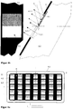
- FIGS. 1a and 1b An example of such a matching is in the FIGS. 1a and 1b outlined.
- a viewing booth 1 stands next to a screen 2.
- a lighting system comprising a plurality of fluorescent tubes L1-L3 is arranged obliquely over a viewing area 4.
- This illumination L1-L3 emits light 3, consisting of directly incident light radiation 3.1 and indirect light by reflected light radiation 3.2, 3.3 on a viewing surface 4.
- An original color sample 4.1 is located on the viewing area 4 in the cabin 1, their color reproduction 4.2 appears on the Screen 2.
- Such patching stations are well known and correspond to products of various suppliers available on the market.
- a color 4.1 to be compared is measured for electronic reproduction with a colorimeter or recorded with a color scanner for a full color image, and its color values are reproduced on the screen in electronic form as an image.
- Color values as a measure of color are standardized in the art by the CIE1931 2-degree standard observer or the CIE1964 10-degree standard observer. The measuring technique for measuring the color values is described in DIN 5033 or for the graphic industry in the standard ISO 13655.
- Conventional colorimeters provide color values either as standardized CIE1931 XYZ values (integral colorimeter) or they measure the spectral reflectance ⁇ ( ⁇ ) of the color sample (spectrophotometer).
- X k ⁇ 380 nm 780 nm S ⁇ ⁇ ⁇ x ⁇ d ⁇ .
- Y k ⁇ 380 nm 780 nm S ⁇ ⁇ ⁇ y ⁇ d ⁇ .
- Z k ⁇ 380 nm 780 nm S ⁇ ⁇ ⁇ z ⁇ d ⁇
- the color values are always defined as relative quantities and k is a normalization constant.
- k is a normalization constant.
- the spectral color stimulus reflected by the sample is picked up by the eye of a human observer and strikes the retina of the eye where it triggers the color perception of the human observer. All spectral components are integrated to determine the standard color values over the visible wavelength range of 380 to 780 nm for the human eye.
- the color values are related quantities and differ from absolute sizes, e.g. in light flux or light intensity and determine the absolute brightness of a color.
- a first reason for colors which often do not coincide is that color measuring instruments, with which the spectral reflection of a color is determined, use a specific illumination geometry, as defined, for example, in DIN 5033.
- This can be for example a directional illumination below 45 degrees (so-called 45/0 Geometry), where an observer looks perpendicular to the sample.
- a 0/45 degree geometry is also used, in which the sample is illuminated vertically and the observer looks at the sample at 45 degrees or a diffuse light measurement with an integrating sphere.
- a defined lighting geometry such as that in a colorimeter can not be reproduced exactly.
- a light source is realized by several fluorescent tubes in the upper area of a cabin to illuminate a sample. In order to increase the homogeneity of the illumination, cabins are also known which use another fluorescent tube in the lower area of the cabin.
- the light falling directly onto the sample from the light sources should have a constant spectral distribution on the viewing surface, since the consideration of a location-dependent spectral distribution in the color calculation would be very complicated.
- additional reflected light (3.2, 3.3 in FIG. 1 b) passed to the sample, which is converted by the spectral reflection properties of the walls in a different spectral distribution than that of the direct radiation 3.1.
- This is superimposed with locally different distribution of the direct light, eg near the walls with a stronger influence than in the middle of the picture.
- reflectors R1 - R3 are often mounted behind the fluorescent tubes to direct additional light to the sample. This measure also leads to locally different spectral components due to the wavelength-dependent reflection of the reflectors.
- the illumination 3 of the sample is therefore neither completely spectrally homogeneous nor is a clearly defined illumination geometry reproduced as in measuring devices.
- scattering plates P are arranged in front of the light sources. These are often made of plastics with a certain corrugation. Due to the wavelength-dependent refraction of light on plastics, the transmitted light radiation is then to be expected with an angle-dependent spectral distribution.
- the light reflected additionally by the reflection of the image surface by room light causes a reduction of the image contrast.
- the spectral composition of the room light has not yet been taken into account for the calculation of the color to be reproduced.
- the illuminance on the support surface changes depending on location.
- the distribution of the luminance on a screen is not completely constant but changes locally.
- differences in illumination in the viewing box can range from 10% to 20%.
- screens typical differences in luminance from the center of the picture to the edge of the picture are in this area, but their distribution is different from the distribution in the viewing booth.
- a viewing booth which uses an additional light source in the ground area to reduce the decrease in illuminance in the vertical direction.
- Essential in the appearance of a color is the so-called state of adaptation of the eye. Parameters that control the visual appearance of a color in the brain of a person depend on the brightness and color distribution of the colors in the field of vision, and the human visual system adjusts and adapts to it within a period of about 2 minutes ,
- FIGS. 1a and 1b sketched scanning arrangement to the fact that the colors of the original document under the illumination of the viewing booth in the field of view of a human observer appear in a different way than happens after a change of the viewing direction on the screen with other environment.
- the state of adaptation of the eye changes when the human observer looks longer in one of the directions. Since the totality of all the colors and magnitudes of the illumination in the visual field of the human observer when looking back and forth in comparison usually do not match, Also, the colors on the screen next to the cab appear different than the original colors in the viewing booth.
- at least one ambient brightness is usually provided which corresponds to approximately 20% of the brightness of the maximum white value in the image display. In the viewing booth, however, the direct environment of a color original is illuminated with the same brightness as the sample itself.
- a white frame 4.3 around the viewing samples or the screen and therefore to create a neutral gray surrounding area.
- the total area is illuminated as uniformly as possible with one or more rod-shaped light sources L1-L3.
- the geometry of the illumination is approximately 45/0 degrees geometry and the original color sample and the reproduced color on the screen are arranged in the same environment under the same illumination and thus lead to the same color appearance.
- the object of the invention is to propose solutions which avoid the problems mentioned under 1.1 to 1.5, and to ensure a visually guaranteed equal visual reproduction of colors on the screen in comparison with original colors under a defined lighting for the observer.
- the screen can be influenced by adjusting parameters by means of software and electronic control in each sub-area of the screen, to improve that in each sub-area of the screen the reproduced color impression of the screen is adapted to the color impression of an original by the original immediately adjacent is compared on the screen surface with the screen colors and the screen parameters are changed until the color impression of the original and the screen at the respectiveêtunterfläc for an observer, viewed from a predetermined observer angle, appears identical, and the adjustments made are deposited in a screen profile, using a mask in front of the screen that contains a number of windows distributed over the entire image area, each window partially, preferably covered in half, with an original of a surface color and behind each of the uncovered window part surfaces on the screen, the color reproduction associated with the respective surface color is generated, and the software runs in a computer controlling the screen, with which the brightness of the reproduced colors in each Window can be changed and adjusted so that the observer no longer has a difference in brightness between original and reproduced color under the illumination of the screen, and the brightness values
- the screen is arranged in a color neutral designed surface, illuminated this area under approximately 45 degrees by a, preferably rod-shaped, light source and arranged original color samples on the screen surface, so that the reproduced colors on the screen in the direct Comparison next to or abutting on the original colors for a human observer to the same color perception.
- variable fundamental spectral value curves of observers can be used for the color calculation, which on the one hand are better adapted to the human users than those of the standard observer and, on the other hand, made dependent on the mean observed color area size or the associated observer angle of a contiguous color area, the screen calibration also being variable as a function of the respectively used basic spectral value curves is calculated.
- each window is covered in half with an original of a surface color.
- the camera is equipped with an optical filter, which together with the spectral sensitivity of the camera results in a total spectral sensitivity of the image recording, which corresponds to a spectral light sensitivity V ⁇ of a selected observer.
- the color stimuli occurring due to reflection of the light on the screen surface in the direction of the observer are measured in their spectral distribution and their intensity, these color stimuli are described as reflected color values of the screen for the observer and on the screen only the differences of color values of original colors and the reflected color values are reproduced.
- the color stimuli occurring due to reflection of the light on the screen surface in the direction of the observer are directly measured during the measurement of the screen profile when the illumination is switched on and are then contained in the or a stored screen profile.
- the spectral distribution of the illumination is measured with the aid of a spectrometer arranged directly on the screen, and the result of the spectral light distribution is taken into account when the screen profile is generated.
- the screen is operated under an internal light source in a cabin and in addition from the outside on the viewing surface incident light with the same or different spectral distribution is included in the calculation of the reproduction of the color, wherein the local Color distribution is determined separately for the incident light from the outside and the light originating from the internal light source and the color reproduction is represented as the sum of the color values under the internal and external illumination.
- the brightness distribution of the light incident from the outside is measured when the internal light source is switched off via sensors which are distributed on the viewing surface in the cabin.
- variable fundamental spectral value curves which depend on the size of a color area and its resulting observer angle are used to calculate the colors from the spectral reflection properties of original colors and to calculate the color reproduction over the screen, and a color image in Areas approximately equal to the same or appearing on average the same appearances colors and the respectively associated observer angle is determined for a segment from the respective mean sizes of a color segment in an image.
- a database is constructed in which analytically described or stored in stages as a function of the observer angle, the basic spectral value curves of different observers, color values of original colors from their spectral reflection for the variable Basic spectral value curves are formed, the screen colors described from their spectral radiation distribution on the screen and color values for the construction of screen profiles depending on observers and observer angles are calculated, stored these screen profiles in real time processing for the color reproduction of images or as pre-calculated profiles in a database and Depending on the selected observer and observer angle are called.
- claim 12 proposes the use of a device for reproducing a color impression of an original by an observer.
- a device for reproducing a color impression of an original by an observer In today's conventional method for soft proof is trying to make the illumination distribution on the viewing surface of the original and the distribution of luminance on the screen in each case so or correct that the best possible uniformity is achieved. In practice, however, this encounters great technical difficulties and a uniformity in the range of 1% of the average brightness is not achieved. However, to achieve invisible differences in reproduction from the original colors, accuracy of 1% is required.
- the screen brightness is now adapted exactly to an existing location-dependent illumination, thus achieving a high accuracy of directly adjacent original colors and their reproduction of better than 1% of the brightness differences, with local brightness differences of greater than 1 over the entire image area % allowed are.
- color values are exemplified by XYZ values and basic spectral value curves by x ( ⁇ ), y ( ⁇ ), and z ( ⁇ ) which do not necessarily correspond to the standard color values and the standard spectral value curves, respectively.
- x ( ⁇ ), y ( ⁇ ), and z ( ⁇ ) which do not necessarily correspond to the standard color values and the standard spectral value curves, respectively.
- color values or basic spectral value curves can be represented by the law of colorimetry by any linear combinations of color mixing curves that have been determined for a human observer.
- the invention further assumes that all the original colors to be reproduced are described by their spectral reflection properties. These can be measured with commercially available spectrophotometers if homogeneous colored surfaces are present. For images, it is assumed that multispectral images are present, in which the spectrum of reflection of recorded images is described for each pixel.
- FIG. 3 a possible basic structure for the color reproduction and the illumination of the comparison sample according to the inventive concept is shown.
- the aim of the invention is to allow a completely reliable and always controllable color reproduction on a screen in comparison to original surface colors under a defined and clearly spectrally described light source.
- a viewing area 4 is arranged in a viewing booth 1, into which the screen 2 with its area 2.2 is fitted.
- the viewing area 4 is illuminated by a preferably rod-shaped light source L1.
- the length of this light source L1 covers the entire width of the viewing booth 1 and is deliberately chosen to be longer than the screen width, so that in the region of the screen in the horizontal direction as uniform as possible illuminance is achieved.
- the inclination of the viewing surface 4 is selected so that the direct rays of the light source impinge at approximately 45 degrees on the center of the image. It is further assumed that a human observer 5 looks perpendicular to the image center under normal viewing conditions. This illumination then approximates the standard established when measuring colors according to DIN 5033 under the illumination angle of 45 ° and the observer angle of 0 degrees (45/0 degrees).
- the invention can also be embodied with a surface-extended light source-on the one hand, one or a few surface-area-configured light sources or, on the other hand, it can be a multiplicity of punctiform and areally distributed light sources.
- the measurement of the original colors should also have a measurement geometry which uses the same geometry of the incident light rays as they produce relative to the viewing surface, since otherwise color-identical reproduction is scarcely possible.
- LED luminaires which additionally offer the advantage that the uniformity of the local distribution of the lighting can be improved by targeted control of the brightness of the LED luminaires.
- the active surface 2.2 of the screen is surrounded, for example, in the area of the illumination with a color-uniform surface 4.
- a white frame may be arranged around the image surface, as disclosed in the patent application DE 101 21 984.9 described and justified.
- the white frame 4.3 has proved to be expedient, since it stabilizes the adaptation state of the eye and thus the color perception of an image representation and defines it with its color values Xw, Yw and Zw (the index w stands for white) under the illumination of a reference light.
- the frame should as far as possible be coated with a white and matte surface of approximately constant spectral reflectance in the visible region, and should not contain any optical brighteners.
- an original sample 4.1 can be positioned either in the immediate vicinity of the screen or on the screen. In the latter case, a best color comparison is possible if a reproduction 4.2 of the color on the screen is directly adjacent to the original sample.
- the color values of a sample must first be determined.
- the spectral light distribution S ⁇ at the location of the sample must be measured with a spectroradiometer.
- the color values XYZ or the color stimuli reflected in the direction of the observer can then be calculated.
- the thus determined color values of the image of the color sample 4.1 are electronically reproduced on the screen with the aid of the known methods for controlling screens such that the same color values XYZ appear in the color field 4.2 on the screen. If this is the case with sufficient accuracy considering the colorimetric characteristics of the observer, then the electronically reproduced color in the viewing device is perceived by an observer exactly as the original sample directly adjacent to the field of the reproduced color.
- the color values of the sample are known only as relative values and it still has to be determined with which absolute brightness they have to be reproduced on the screen 2.
- a visual comparison method is used according to the invention, with which a brightness profile is created.
- a mask 6 is attached in front of the screen, which contain a number of regularly arranged windows with centers 6.2. The centers of the windows form a uniform grid over the image area.
- Behind each window is in each case a physical test color area 4.1, for example, a homogeneous printed paper sample attached, which covers each example, the upper half of a window.
- the lower half is open and behind these openings the colors 4.2 are reproduced through the screen. The reproduced colors thus touch directly on their originals and can be compared as best as possible.
- a software is used to determine the brightness profile, with which the brightness of each reproduced color can be set individually in a window.
- This setting is e.g. performed manually via a separate screen menu of a computer controlling the color display screen 2.
- the radiation 4.1.1 of the original color 4.1 reflected from each test color and the directly adjacent radiation 4.2.1 of the screen lead to color stimuli that can be compared in the eye of the human observer in front of the screen with the best possible sensitivity. Visually, this allows a sensitive adjustment of the brightness in each window.
- the brightness values in the center of each window after the adjustment has been made are then saved as a grid over the screen area.
- a subsequent two-dimensional interpolation realizes a brightness profile above the screen, which is included as a reference in the location to be reproduced colors and thus guarantees an exact reproduction of the absolute brightness of the colors in each pixel. It is assumed that the brightness on the screen changes only steadily and not abruptly due to the lighting.
- the image of the mask 6 is scanned with a camera which records the entire image.
- the camera must be equipped with suitable optical filters taking into account the spectral sensitivity of the image sensor so that their effective spectral sensitivity is adapted to the brightness sensitivity curve V ⁇ of the observer.
- the areas of each window of the mask with upper and lower sections are then selected in the camera image and averaged signals are formed therein.
- the absolute magnitude of the signals across the image surface is unreliable because of the optical imaging and homogeneity of the image sensor.
- the respective brightness value behind each window of the screen is automatically controlled in a control loop by the software so that the signals detected by the measuring camera for the upper and lower halves of each window are just the same size, so their difference disappears.
- the absolute signal values then play no role anymore.
- the brightness values thus found for the control of the screen are stored and interpolated for the further application.
- the light radiation used to illuminate the original colors also hits the surface of the screen. Part of the incident light is thus reflected in the direction of the observer in addition to the color values Xp, Yp and Zp of the reproduction. In order to compensate for this influence, the fraction reflected on the image surface is measured radiometrically and from this, reflected color values Xr, Yr and Zr are calculated. For a reproduction of a color value Xp, Yp and Zp, these components are then first subtracted and only the difference Xr-Xp, Yr-Yp and Zr-Zp is reproduced as color on the screen.
- the portion reflected on the screen surface then physically adds to the reproduced one of the screen and, in sum, gives the desired values of the original color.
- the measured brightness profile must be taken into account in order to calculate the values Xr, Yr and Zr.
- the light components reflected on the screen surface reduce the effective image contrast, because the minimum color values on the image surface then correspond at least to the reflected light component. For the application of the invention, therefore, care must be taken that a screen with low surface reflection is used.
- the in the cabin 1 in FIG. 3 arranged viewing surface 4 with the screen 2 is in the upper region relatively close to the light source L1 and in the lower region relatively far away from the light source. This results in differences in illuminance at the top and bottom of the screen.
- a human observer can very sensitively distinguish the brightnesses directly abutting color surfaces, brightness differences over longer distances, on the other hand, can only be perceived very insensitive, since the visual system perceives the perceived brightness after a course following the third root of the physical intensity. Brightness differences in the range of 10% over the image area are therefore hardly noticed. Larger differences, on the other hand, are disturbing.
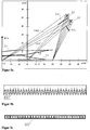
- FIG. 5a A typical example according to the invention is in FIG. 5a outlined. Shown is a section through the surface of the screen 2 in a horizontal position. The dimension of the x- and y-coordinates corresponds with - 15 the lower edge of the picture, with +15 the upper edge of the picture. Furthermore, in the x / y coordinate system, two light-emitting tubes L1 and L2 lying close to each other are outlined by way of example as illumination, by their cross-section. In front of the fluorescent tubes two light masks 3.4.1 and 3.5.1 are arranged, which have a profile corresponding to those in the FIGS. 5b and 5c have shown rectangular longitudinal sections.
- the light masks 3.4.1 and 3.5.1 are arranged in such a way that all light components 3.4.2 and 3.5.2 of both fluorescent tubes still reach the lower edge of the image at position -15 unhindered.
- the light components are increasingly shaded.
- the corresponding course through the arc tube L2 is shown in 7.2.
- the procedure according to the invention is the same as described above for the calculation of colors under the main light source.
- the spectral distribution of the incident light must first be measured with a radiometer. Radiometers are currently relatively expensive and expensive. In the long term, however, it can also be envisaged to install a radiometer in the front area of the viewing booth and thus to continuously measure the spectral distribution of incident extraneous light.
- the brightness profile on the screen surface should also be determined for the calculation by means of room light.
- the internal light source of the viewing booth is switched off and the technique with the test mask according to the FIGS. 4a and 4b in the same way as described above for the internal light source.
- the color values of the original colors in the windows of the mask are then calculated for the spectral distribution of the extraneous light.
- the color values X P, F , Y P, F and Z P, F to be reproduced are determined. In this case, the reflection of extraneous light on the screen surface is taken into account again. Then, when the calculated values are reproduced on the screen, the original colors appear identical to the reproduced colors.
- the reproduction with internal illumination 3 switched on then uses the superposition principle, provided that the screen profile provides a corresponding linearization of the representation of color values, ie the color values X P + X P, F , Y P + Y P, F and Z P + Z P, F shown on the screen.
- a brightness profile initially precisely determined for extraneous light be readjusted, for example by mathematically adjusting the edge parameters of the profile by global bending of the profile to the measured values when the extraneous light changes. Since the sensors are in the plane in which color samples may be applied during operation of the workstation, recalibration should be automated using the signals from the sensors 8, for example, at the beginning of a work phase or after being displayed on a monitor of a control computer. During this recalibration, the viewing area must be kept clear.
- FIG. 6 is also outlined a possible position 9 for the spectral measurement of extraneous light with a fixed radiometer, which constantly determines the spectral distribution of extraneous light and fed into the calculation.
- the entire illumination of the screen be limited only by a fixed room lighting e.g. as a ceiling lighting in a room to realize, so no cabin to use more.
- the method of color reproduction by measuring the spectral distribution and brightness of the illumination at the location of the screen can then also be applied.
- the ceiling light should preferably impinge on the image surface at approximately 45 degrees, and gloss effects due to light in the vicinity of the direction perpendicular to the screen must be avoided.
- this solution requires a constant illumination time in a closed space. Changes in the brightness of colors that can be reproduced on the screen are limited by the maximum image brightness. As a result, the high brightness of natural sunlight and light incident through a window are not reproducible, at least with the screen technology currently available.
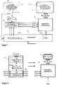
- FIG. 7 shows exemplarily how variable spectral value curves can be used in the image reproduction according to the invention. That the spectral value x i ( ⁇ , ⁇ ), y i ( ⁇ , ⁇ ) and z i ( ⁇ , ⁇ ) is assumed for different observers and i in steps stepped observer angle ⁇ in a database 10 by 10.1 is stored. For a reproduction an observer i must be selected. The choice of the observer angle ⁇ valid for a color surface can be derived from the image information to be displayed. The image is then segmented into areas of approximately the same color. For such a region 11.1, a mean size is then determined, for example, from the surface area, which is then assigned to a mean diameter D of the color surface.
- the calculated respectively for a pixel color value X P ( ⁇ ), Y P ( ⁇ ) and Z P ( ⁇ ) is reproduced by a watcher specific screen profile P i ⁇ on the screen by the signal value calculation 16 via the screen profile P i ⁇ ⁇ the control signals R P , G P and B P of the screen 2 are calculated for a color and on the color image 11.2 on the screen 2 are reproduced.
- a so-called inverted model For the application for the reproduction of colors, a so-called inverted model has to be determined from this model, which assigns the necessary RGB signals to the input to the given color values to be reproduced.
- the basic procedure for creating such a screen profile is known, but today only screen profiles based on a standard observer are created according to CIE and all available software methods for the "color management" of screens are designed only for this purpose.
- FIG. 8 The method for generating a screen profile P i ( ⁇ ) for an arbitrary observer i as a function of the observer angle ⁇ is exemplified in FIG. 8 outlined.
- the procedure of the measurement technique and the determination of color values 15 are described on the screen.
- the spectra S ⁇ , B of the screen colors for any input signals R, G, B of the screen are measured with a spectroradiometer 13.
- the color values 15 are calculated with X ( ⁇ ), Y ( ⁇ ), Z ( ⁇ ) from which the basic spectral value curves of a selected observer x i ( ⁇ , ⁇ ), y i ( ⁇ , ⁇ ), z i ( ⁇ , ⁇ ) are read.
- a mathematical backward model 12 is created as an analytical model or interpolatable support point grid. This is then mathematically inverted and within the scope of the application of the present invention in the database 10 in FIG FIG. 8 saved.
Landscapes
- Physics & Mathematics (AREA)
- Spectroscopy & Molecular Physics (AREA)
- General Physics & Mathematics (AREA)
- Engineering & Computer Science (AREA)
- Mathematical Physics (AREA)
- Theoretical Computer Science (AREA)
- Multimedia (AREA)
- Signal Processing (AREA)
- Spectrometry And Color Measurement (AREA)
- Facsimile Image Signal Circuits (AREA)
- Controls And Circuits For Display Device (AREA)
Claims (12)
- Procédé de pcalibration d'écran pour la reproduction fidèle à l'original de couleurs de surface, dont la distribution spectrale de réflection est connue et mesurée, sur un écran, lequel est utilisé sous une lumière incidente venant d'au moins une source de lumière avec un angle d'incidence de la lumière hors de l'angle de Bragg et avec une distribution spectrale connue, dans lequel l'écran peut être influencé par la configuration de paramètres à l'aide d'un logiciel et d'une commande électronique dans chaque partie de l'écran,
caractérisé en ce que1.1 dans chaque partie de l'écran l'impression couleur reproduite de l'écran est adaptée à l'impression couleur d'un original, l'original étant comparé avec les couleurs de l'écran en étant directement adjacent à la surface de l'écran et les paramètres d'affichage étant modifiés jusqu'à ce que l'impression couleur de l'original paraisse identique à l'impression couleur de l'écran dans la partie de l'écran observée pour un observateur depuis un angle d'observation prédéfini,1.2 et les réglages effectués étant enregistrés dans un profil d'écran, dans lequel1.3 un masque est utilisé devant l'écran, contenant un nombre de fenêtres réparties sur toute la surface de l'écran, dans lequel chaque fenêtre est couverte partiellement, de préférence à moitié, par un original d'une surface de couleur et la reproduction couleur ordonnée à la surface de couleur respective est produite derrière chacune des parties de fenêtre non recouvertes sur l'écran, et1.4 le logiciel est en cours d'exécution sur un ordinateur contrôlant l'écran, permettant de modifier la luminosité des couleurs reproduites dans chaque fenêtre et pouvant être configuré de façon à1.4.1 ce qu'il n'y ait pour l'observateur aucune différence de luminosité entre la couleur originale et la couleur reproduite sous l'éclairage de l'écran, et1.4.2 les valeurs de luminosité soient enregistrées comme points de repère et un profil de luminosité soit établi à partir de celles-ci, lequel commande la luminosité absolue pour chacune des couleurs reproduites dans un élément de l'image, et1.5 le réglage de luminosité et la détermination des points de repère pour le profil de luminosité de l'écran sont ainsi effectués automatiquement, en ce qu'en tant qu'observateur une caméra enregistre l'image du masque,1.5.1 dans lequel pour chaque fenêtre du masque la zone des couleurs de surface et la zone des couleurs reproduites par l'écran sont sélectionnées et les signaux de couleurs mesurés et moyennés dans ces zones sont produits,1.5.2 ces signaux de couleurs sont transmis à un ordinateur, lequel commande le moniteur, et la luminosité des signaux est ainsi modifiée de manière itérative jusqu'à ce que dans chaque fenêtre les signaux de couleur produits par la surface de couleur et par sa reproduction soient identiques. - Procédé selon la revendication 1 ci-dessus, caractérisé en ce que chaque fenêtre est recouverte à moitié par un original d'une surface de couleur.
- Procédé selon l'une des revendications 1 et 2 ci-dessus, caractérisé en ce que la caméra est équipée d'un filtre optique, lequel fournit en combinaison avec la sensibilité spectrale de la caméra une sensibilité spectrale totale de l'acquisition d'image, qui correspond à une sensibilité spectrale de luminosité Vλ d'un observateur sélectionné.
- Procédé selon l'une des revendications 1 à 3 ci-dessus, caractérisé en ce que4.1 les stimuli de couleur survenant par réflection de la lumière sur la surface de l'écran dans la direction de l'observateur sont mesurés en distribution spectrale et en intensité,4.2 ces stimuli sont décrits comme valeurs chromatiques réfléchies de l'écran pour l'observateur4.3 et seules les différences entre les valeurs chromatiques des couleurs originales et les valeurs chromatiques réfléchies sont reproduites.
- Procédé selon l'une des revendications 1 à 4 ci-dessus, caractérisé en ce que les stimuli de couleur survenant par réflection de la lumière sur la surface de l'écran dans la direction de l'observateur sont mesurés directement lors de la mesure du profil de l'écran avec éclairage allumé et ensuite contenus dans ce profil ou dans un profil enregistré.
- Procédé selon l'une des revendications 1 à 5 ci-dessus, caractérisé en ce que6.1 l'écran est agencé dans une cabine,6.2 le centre horizontal de l'écran est éclairé en section verticale sous un angle de 45°, l'éclairage étant effectué au moyen de sources lumineuses étendues en forme de bâtonnet, lesquelles sont montées au-dessus ou en dessous de l'écran,6.3 et une homogénéisation de la distribution d'éclairage sur la surface de l'image est obtenue, des recouvrements de fraction lumineuse (= masques) étant disposés dans le chemin d'onde de la lumière entre la source lumineuse et l'écran, et bloquant ou laissant passer, en raison de leur conception, les ondes lumineuses de la source lumineuse sur le chemin de l'écran en fonction du lieu et/ou de l'angle.
- Procédé selon l'une des revendications 1 à 6 ci-dessus, caractérisé en ce que la distribution spectrale de l'éclairage est mesurée à l'aide d'un spectromètre directement agencé à l'écran et en ce que le résultat de la distribution spectrale est pris en compte lors de la création du profil de l'écran.
- Procédé selon l'une des revendications 1 à 5 ci-dessus, caractérisé en ce que l'écran est utilisé sous une source de lumière dans une cabine et qu'en outre la lumière incidente à la surface d'observation provenant de l'extérieur, dotée d'une distribution spectrale identique ou différente, est intégrée dans le calcul de la reproduction de la couleur, dans lequel la fraction colorée locale est déterminée séparément pour la lumière incidente provenant de l'extérieur et la lumière émanant de la source interne et la reproduction des couleurs est réalisée comme somme des valeurs chromatiques sous l'éclairage interne et externe.
- Procédé selon la revendication 8 ci-dessus, caractérisé en ce que la distribution de luminosité de la lumière incidente venue de l'extérieur est mesurée, lorsque la source de lumière interne est éteinte, au moyen de capteurs répartis sur la surface d'observation de la cabine.
- Procédé selon l'une des revendications 1 à 9 ci-dessus, caractérisé en ce10.1 qu'afin de calculer les couleurs à partir des propriétés de réflection spectrale des couleurs originales et afin de calculer la reproduction des couleurs sur l'écran, des courbes variables de valeurs spectrales de base, qui sont fonction de la taille de la surface colorée et de l'angle d'observation qui en résulte, sont utilisées,10.2 et une image couleur est segmentée en zones de couleurs approximativement identiques ou en moyenne sensiblement identiques et l'angle d'observation respectivement agencé pour un segment est déterminé à partir de la taille moyenne respective d'un segment de couleur dans une image.
- Procédé selon l'une des revendications 1 à 10 ci-dessus, caractérisé en ce11.1 qu'une base de données est constituée pour la reproduction des couleurs avec différents observateurs, les courbes de valeurs spectrales de base de différents observateurs sont décrites analytiquement ou par parties en fonction de l'angle d'observation,11.2 les valeurs chromatiques des couleurs originales sont obtenues à partir de leur réflection spectrale pour les courbes variables de valeurs spectrales de base,11.3 les couleurs à l'écran sont décrites à partir de leur distribution spectrale de rayonnement sur l'écran et, à partir de celles-ci, les valeurs chromatiques pour la création de profils d'écran sont calculées en fonction des observateurs et des angles d'observation,11.4 ces profils d'écrans sont utilisés dans le traitement en temps réel pour la reproduction couleur d'images ou disposés en tant que profils précalculés dans une banque de données et sont chargés en fonction de l'observateur et de l'angle d'observation sélectionné.
- Application d'un dispositif pour la reproduction d'une impression couleur d'un original par un observateur, comprenant- un écran pour la reproduction couleur,- un masque devant l'écran, contenant un nombre de fenêtres réparties sur toute la surface de l'écran, dans lequel chaque fenêtre peut être couverte partiellement, de préférence à moitié, par un original d'une surface de couleur et la reproduction couleur ordonnée à la surface de couleur respective peut être produite derrière chacune des parties de fenêtre non recouvertes sur l'écran,- une caméra,- un ordinateur doté d'un logiciel de commande de l'écran et- un dispositif d'éclairage pour l'éclairage défini de l'environnement de l'écran, dans lequel 12.1 l'écran est agencé dans une cabine ou dans une pièce,12.2 l'éclairage est effectué au moyen de sources lumineuses étendues en forme de bâtonnet, lesquelles sont montées au-dessus ou en dessous de l'écran de telle sorte que le centre horizontal de l'écran est éclairé en section verticale sous un angle de 45°,12.3 une homogénéisation de la distribution d'éclairage sur la surface de l'image est obtenue, des recouvrements de fraction lumineuse étant agencés dans le chemin d'onde de la lumière entre la source lumineuse et l'écran, et bloquant ou laissant passer, en raison de leur conception, les ondes lumineuses de la source lumineuse sur le chemin de l'écran en fonction du lieu et/ou de l'angle, et12.4 un logiciel est présent dans l'ordinateur et effectue en fonctionnement le procédé selon une des revendications 1 à 11.
Applications Claiming Priority (2)
| Application Number | Priority Date | Filing Date | Title |
|---|---|---|---|
| DE102008021148.6A DE102008021148B4 (de) | 2008-04-28 | 2008-04-28 | Verfahren und Vorrichtung zur originalgetreuen Wiedergabe von Farben auf Bildschirmen |
| PCT/IB2009/005959 WO2009133471A2 (fr) | 2008-04-28 | 2009-06-16 | Procédé et dispositif permettant le rendu de couleurs sur des écrans de manière fidèle à un original |
Publications (2)
| Publication Number | Publication Date |
|---|---|
| EP2277304A2 EP2277304A2 (fr) | 2011-01-26 |
| EP2277304B1 true EP2277304B1 (fr) | 2018-07-18 |
Family
ID=41111864
Family Applications (1)
| Application Number | Title | Priority Date | Filing Date |
|---|---|---|---|
| EP09738484.6A Not-in-force EP2277304B1 (fr) | 2008-04-28 | 2009-06-16 | Procédé et dispositif permettant le rendu de couleurs sur des écrans de manière fidèle à un original |
Country Status (5)
| Country | Link |
|---|---|
| US (1) | US9560242B2 (fr) |
| EP (1) | EP2277304B1 (fr) |
| CN (1) | CN102124723B (fr) |
| DE (1) | DE102008021148B4 (fr) |
| WO (1) | WO2009133471A2 (fr) |
Families Citing this family (15)
| Publication number | Priority date | Publication date | Assignee | Title |
|---|---|---|---|---|
| DE102008021148B4 (de) | 2008-04-28 | 2014-02-13 | Caddon Color Technology Gmbh | Verfahren und Vorrichtung zur originalgetreuen Wiedergabe von Farben auf Bildschirmen |
| DE102010024090A1 (de) * | 2010-06-17 | 2011-12-22 | Bavaria Digital Technik Gmbh | Farbprüfleuchte |
| WO2012150136A2 (fr) * | 2011-05-05 | 2012-11-08 | Koenig & Bauer Aktiengesellschaft | Systèmes d'évaluation d'un exemplaire de produit sur le poste de conduite d'une machine à imprimer |
| US20130006532A1 (en) * | 2011-06-30 | 2013-01-03 | Advan Int'l Corp. | Portable calibration apparatus for medical monitor |
| KR102386112B1 (ko) * | 2015-07-30 | 2022-04-14 | 삼성디스플레이 주식회사 | 표시 장치 |
| US10431139B2 (en) * | 2017-07-25 | 2019-10-01 | Lenovo (Singapore) Pte. Ltd. | Screen color calibration |
| US10354573B2 (en) * | 2017-07-25 | 2019-07-16 | Lenovo (Singapore) Pte Ltd | Screen color calibration |
| CN108616697B (zh) * | 2018-07-27 | 2020-12-01 | Oppo广东移动通信有限公司 | 拍摄状态的提醒方法、装置、存储介质及电子设备 |
| CN110875021A (zh) * | 2018-08-29 | 2020-03-10 | 中兴通讯股份有限公司 | 屏幕显示控制方法、装置、设备、及可读存储介质 |
| FR3085519B1 (fr) * | 2018-09-04 | 2023-01-13 | Centre Nat Rech Scient | Procede de mesure d'un espace de couleur propre a un individu et procede de correction d'images numeriques en fonction de l'espace de couleur propre a l'individu |
| CN113063498A (zh) * | 2021-03-26 | 2021-07-02 | 重庆晨旭商显科技有限公司 | 大尺寸点亮色差缺陷对比卡检验方法 |
| CN113075230A (zh) * | 2021-03-26 | 2021-07-06 | 重庆烯宇新材料科技有限公司 | 大尺寸点亮显示外观检验方法 |
| US12462773B1 (en) * | 2022-02-11 | 2025-11-04 | Baylor University | Optimization of image perception for color vision deficiencies |
| CN117309147B (zh) * | 2023-09-22 | 2025-08-12 | 神力视界(深圳)文化科技有限公司 | 针对虚拟拍摄系统的颜色校准方法、装置、设备及介质 |
| CN121120511A (zh) * | 2025-08-18 | 2025-12-12 | 杭州新洋科技有限公司 | 一种花纹色差识别方法及系统 |
Family Cites Families (25)
| Publication number | Priority date | Publication date | Assignee | Title |
|---|---|---|---|---|
| US4106846A (en) * | 1976-11-15 | 1978-08-15 | Russin Morton S | Television color bar matching device |
| DE4119489C2 (de) | 1991-06-13 | 1994-09-29 | Linotype Hell Ag Werk Kiel | Multispektrales Farbbildaufnahmesystem |
| GB2260631B (en) | 1991-10-17 | 1995-06-28 | Intel Corp | Microprocessor 2X core design |
| US5670985A (en) * | 1994-05-09 | 1997-09-23 | Apple Computer, Inc. | System and method for adjusting the output of an output device to compensate for ambient illumination |
| US5638117A (en) * | 1994-11-14 | 1997-06-10 | Sonnetech, Ltd. | Interactive method and system for color characterization and calibration of display device |
| US7728845B2 (en) * | 1996-02-26 | 2010-06-01 | Rah Color Technologies Llc | Color calibration of color image rendering devices |
| US6459425B1 (en) * | 1997-08-25 | 2002-10-01 | Richard A. Holub | System for automatic color calibration |
| DE19755655A1 (de) | 1997-12-15 | 1999-06-17 | Logo Kommunikations Und Druckt | Verfahren zur farbmetrischen Charakterisierung eines selbstleuchtenden Abbildungssystems |
| US6816145B1 (en) * | 1998-07-22 | 2004-11-09 | Silicon Graphics, Inc. | Large area wide aspect ratio flat panel monitor having high resolution for high information content display |
| US6342952B1 (en) | 1999-10-11 | 2002-01-29 | Flint Ink Corporation | Method for matching printing ink colors |
| US7102648B1 (en) * | 2000-04-11 | 2006-09-05 | Rah Color Technologies Llc | Methods and apparatus for calibrating a color display |
| US6961461B2 (en) * | 2000-05-17 | 2005-11-01 | Tidal Photonics, Inc. | Apparatus and method for measurement, encoding and displaying of object color for digital imaging |
| US7479931B2 (en) * | 2000-10-10 | 2009-01-20 | Sony Corporation | Adjusting apparatus, method, and recording medium, and abnormality display apparatus, method, and recording medium |
| TW554625B (en) * | 2000-12-08 | 2003-09-21 | Silicon Graphics Inc | Compact flat panel color calibration system |
| DE10121984B4 (de) | 2001-04-27 | 2012-09-13 | Color Aixperts Gmbh | Verfahren und Vorrichtung zur visuell optimierten Darstellung von Farbbildern auf Bildschirmen und/oder deren Vergleich mit Originalen oder gedruckten Bildern |
| JP3751621B2 (ja) * | 2003-10-23 | 2006-03-01 | 株式会社ナナオ | 表示特性較正方法、表示特性較正装置及びコンピュータプログラム |
| WO2005052673A2 (fr) * | 2003-11-21 | 2005-06-09 | Sharp Laboratories Of America, Inc. | Affichage a cristaux liquides a couleurs adaptatives |
| US7487118B2 (en) * | 2005-05-06 | 2009-02-03 | Crutchfield Corporation | System and method of image display simulation |
| DE102005028487B4 (de) * | 2005-06-20 | 2007-12-06 | Siemens Ag | Vorrichtung zur Aufnahme und Halterung einer Farbkarte |
| US20070279390A1 (en) * | 2006-06-01 | 2007-12-06 | Dmitrii Loukianov | Method and apparatus for automatic screen calibration and color reproduction in a display system |
| DE102006038200A1 (de) * | 2006-08-16 | 2008-02-21 | Man Roland Druckmaschinen Ag | Leitstand einer Druckmaschine |
| CN101772961B (zh) * | 2007-08-02 | 2012-07-11 | 索尼公司 | 图像处理装置 |
| KR101416246B1 (ko) * | 2007-09-14 | 2014-07-07 | 삼성전자 주식회사 | 디스플레이장치 및 그 제어방법 |
| DE102008021148B4 (de) | 2008-04-28 | 2014-02-13 | Caddon Color Technology Gmbh | Verfahren und Vorrichtung zur originalgetreuen Wiedergabe von Farben auf Bildschirmen |
| JP5375517B2 (ja) * | 2009-10-23 | 2013-12-25 | ソニー株式会社 | 色温度調整装置、色温度調整方法、及びプログラム |
-
2008
- 2008-04-28 DE DE102008021148.6A patent/DE102008021148B4/de not_active Expired - Fee Related
-
2009
- 2009-06-16 WO PCT/IB2009/005959 patent/WO2009133471A2/fr not_active Ceased
- 2009-06-16 US US12/989,702 patent/US9560242B2/en not_active Expired - Fee Related
- 2009-06-16 EP EP09738484.6A patent/EP2277304B1/fr not_active Not-in-force
- 2009-06-16 CN CN200980125565.XA patent/CN102124723B/zh not_active Expired - Fee Related
Non-Patent Citations (1)
| Title |
|---|
| PHIL DOWNEN: "THE STANDARDS for measuring flat- Origins and Applicability of Standards", SID - INFORMATION DISPLAY, 1 January 2006 (2006-01-01), pages 16 - 21, XP055406880, Retrieved from the Internet <URL:http://www.westardisplaytechnologies.com/wp-content/uploads/FPD-Measurement-Standards.pdf> [retrieved on 20170914] * |
Also Published As
| Publication number | Publication date |
|---|---|
| DE102008021148A1 (de) | 2009-10-29 |
| CN102124723A (zh) | 2011-07-13 |
| CN102124723B (zh) | 2015-04-29 |
| WO2009133471A8 (fr) | 2010-12-09 |
| US20110205253A1 (en) | 2011-08-25 |
| DE102008021148B4 (de) | 2014-02-13 |
| WO2009133471A3 (fr) | 2010-07-29 |
| US9560242B2 (en) | 2017-01-31 |
| EP2277304A2 (fr) | 2011-01-26 |
| WO2009133471A2 (fr) | 2009-11-05 |
Similar Documents
| Publication | Publication Date | Title |
|---|---|---|
| EP2277304B1 (fr) | Procédé et dispositif permettant le rendu de couleurs sur des écrans de manière fidèle à un original | |
| EP2270451B1 (fr) | Appareil de mesure de couleur | |
| DE19962779B4 (de) | Vorrichtung zur quantifizierten Bestimmung der Qualität von Oberflächen | |
| DE69329131T2 (de) | Dreidimensionaler automatischer Gonio-Spektrophotometer | |
| DE60106197T2 (de) | Farbsignalverarbeitung | |
| EP2930494B1 (fr) | Appareil de mesure portatif destiné à saisir l'aspect visuel d'un objet de mesure | |
| EP1775565B1 (fr) | Procédé de mesure de couleur d'échantillons imprimés comprenant des azurants optiques | |
| DE102009029391B4 (de) | Bildverarbeitungsgerät und Bildverarbeitungsverfahren | |
| DE112013005127T5 (de) | Bildgebendes Hochpräzisions-Kolorimeter durch Closed-Loop-Kalibrierung mit speziell entworfenen Mustern, gestützt durch einen Spektrographen | |
| EP3467475B1 (fr) | Mesure de scintillement | |
| WO2010124866A1 (fr) | Procédé et dispositif pour effectuer une comparaison optique entre au moins deux modèles, de préférence par comparaison d'extraits sélectionnables | |
| DE10121984B4 (de) | Verfahren und Vorrichtung zur visuell optimierten Darstellung von Farbbildern auf Bildschirmen und/oder deren Vergleich mit Originalen oder gedruckten Bildern | |
| DE10102612A1 (de) | Verfahren und Vorrichtung zur Prüfung der Farb-und/oder Glanz-Qualität von Stoffen oder ähnlichen Materialien | |
| EP4453522A2 (fr) | Procédé et système de colorimétrie | |
| DE102018105794B4 (de) | Abbildung eines Objektes mittels Schattenwurf | |
| EP0928956A2 (fr) | Procédé de caractérisation colorimétrique d'un system d'affichage auto-éclairant | |
| EP0955538A1 (fr) | Procédé et dispositif pour la detection et/ou visualisation de défauts sur la surface d'objets | |
| DE102004059186A1 (de) | Verfahren und Vorrichtung zur ortsauflösenden Bewertung von Oberflächeneigenschaften | |
| DE102018108809B4 (de) | Kamerasystem | |
| EP1602903A2 (fr) | Méthode et dispositif de mesure colorimétrique de laques à effets et unilaques | |
| DE102009004236A1 (de) | TV-Anordnung und Verfahren zur Kalibrierung eines TV-Geräts | |
| DE10019652B4 (de) | Verfahren zur farbmetrischen Auswertung von Multi- und Hyperspektraldaten abbildenden Fernerkundungssensoren | |
| DE4439533C2 (de) | Vorrichtung und Verfahren zur farbmetrischen Erfassung von Farbkontrollfeldern bei der Farbkalibrierung der ausgegebenen Farben von elektronischen Bildverarbeitungssystemen | |
| WO2025172198A1 (fr) | Procédé de détermination d'un mappage d'un premier espace de couleur d'une caméra test sur un second espace de couleur d'un spectromètre | |
| EP4325186A1 (fr) | Dispositif et procédé de détermination de la caractéristique phototechnique d'un luminaire |
Legal Events
| Date | Code | Title | Description |
|---|---|---|---|
| PUAI | Public reference made under article 153(3) epc to a published international application that has entered the european phase |
Free format text: ORIGINAL CODE: 0009012 |
|
| 17P | Request for examination filed |
Effective date: 20101117 |
|
| AK | Designated contracting states |
Kind code of ref document: A2 Designated state(s): AT BE BG CH CY CZ DE DK EE ES FI FR GB GR HR HU IE IS IT LI LT LU LV MC MK MT NL NO PL PT RO SE SI SK TR |
|
| AX | Request for extension of the european patent |
Extension state: AL BA RS |
|
| DAX | Request for extension of the european patent (deleted) | ||
| 17Q | First examination report despatched |
Effective date: 20121019 |
|
| GRAP | Despatch of communication of intention to grant a patent |
Free format text: ORIGINAL CODE: EPIDOSNIGR1 |
|
| STAA | Information on the status of an ep patent application or granted ep patent |
Free format text: STATUS: GRANT OF PATENT IS INTENDED |
|
| INTG | Intention to grant announced |
Effective date: 20180319 |
|
| GRAS | Grant fee paid |
Free format text: ORIGINAL CODE: EPIDOSNIGR3 |
|
| GRAA | (expected) grant |
Free format text: ORIGINAL CODE: 0009210 |
|
| STAA | Information on the status of an ep patent application or granted ep patent |
Free format text: STATUS: THE PATENT HAS BEEN GRANTED |
|
| AK | Designated contracting states |
Kind code of ref document: B1 Designated state(s): AT BE BG CH CY CZ DE DK EE ES FI FR GB GR HR HU IE IS IT LI LT LU LV MC MK MT NL NO PL PT RO SE SI SK TR |
|
| REG | Reference to a national code |
Ref country code: GB Ref legal event code: FG4D Free format text: NOT ENGLISH |
|
| REG | Reference to a national code |
Ref country code: CH Ref legal event code: EP |
|
| REG | Reference to a national code |
Ref country code: IE Ref legal event code: FG4D Free format text: LANGUAGE OF EP DOCUMENT: GERMAN |
|
| REG | Reference to a national code |
Ref country code: DE Ref legal event code: R096 Ref document number: 502009015098 Country of ref document: DE |
|
| REG | Reference to a national code |
Ref country code: AT Ref legal event code: REF Ref document number: 1020605 Country of ref document: AT Kind code of ref document: T Effective date: 20180815 |
|
| REG | Reference to a national code |
Ref country code: NL Ref legal event code: MP Effective date: 20180718 |
|
| REG | Reference to a national code |
Ref country code: LT Ref legal event code: MG4D |
|
| PG25 | Lapsed in a contracting state [announced via postgrant information from national office to epo] |
Ref country code: NL Free format text: LAPSE BECAUSE OF FAILURE TO SUBMIT A TRANSLATION OF THE DESCRIPTION OR TO PAY THE FEE WITHIN THE PRESCRIBED TIME-LIMIT Effective date: 20180718 |
|
| PG25 | Lapsed in a contracting state [announced via postgrant information from national office to epo] |
Ref country code: FI Free format text: LAPSE BECAUSE OF FAILURE TO SUBMIT A TRANSLATION OF THE DESCRIPTION OR TO PAY THE FEE WITHIN THE PRESCRIBED TIME-LIMIT Effective date: 20180718 Ref country code: PL Free format text: LAPSE BECAUSE OF FAILURE TO SUBMIT A TRANSLATION OF THE DESCRIPTION OR TO PAY THE FEE WITHIN THE PRESCRIBED TIME-LIMIT Effective date: 20180718 Ref country code: SE Free format text: LAPSE BECAUSE OF FAILURE TO SUBMIT A TRANSLATION OF THE DESCRIPTION OR TO PAY THE FEE WITHIN THE PRESCRIBED TIME-LIMIT Effective date: 20180718 Ref country code: NO Free format text: LAPSE BECAUSE OF FAILURE TO SUBMIT A TRANSLATION OF THE DESCRIPTION OR TO PAY THE FEE WITHIN THE PRESCRIBED TIME-LIMIT Effective date: 20181018 Ref country code: BG Free format text: LAPSE BECAUSE OF FAILURE TO SUBMIT A TRANSLATION OF THE DESCRIPTION OR TO PAY THE FEE WITHIN THE PRESCRIBED TIME-LIMIT Effective date: 20181018 Ref country code: GR Free format text: LAPSE BECAUSE OF FAILURE TO SUBMIT A TRANSLATION OF THE DESCRIPTION OR TO PAY THE FEE WITHIN THE PRESCRIBED TIME-LIMIT Effective date: 20181019 Ref country code: LT Free format text: LAPSE BECAUSE OF FAILURE TO SUBMIT A TRANSLATION OF THE DESCRIPTION OR TO PAY THE FEE WITHIN THE PRESCRIBED TIME-LIMIT Effective date: 20180718 Ref country code: IS Free format text: LAPSE BECAUSE OF FAILURE TO SUBMIT A TRANSLATION OF THE DESCRIPTION OR TO PAY THE FEE WITHIN THE PRESCRIBED TIME-LIMIT Effective date: 20181118 |
|
| PG25 | Lapsed in a contracting state [announced via postgrant information from national office to epo] |
Ref country code: HR Free format text: LAPSE BECAUSE OF FAILURE TO SUBMIT A TRANSLATION OF THE DESCRIPTION OR TO PAY THE FEE WITHIN THE PRESCRIBED TIME-LIMIT Effective date: 20180718 Ref country code: ES Free format text: LAPSE BECAUSE OF FAILURE TO SUBMIT A TRANSLATION OF THE DESCRIPTION OR TO PAY THE FEE WITHIN THE PRESCRIBED TIME-LIMIT Effective date: 20180718 Ref country code: LV Free format text: LAPSE BECAUSE OF FAILURE TO SUBMIT A TRANSLATION OF THE DESCRIPTION OR TO PAY THE FEE WITHIN THE PRESCRIBED TIME-LIMIT Effective date: 20180718 |
|
| REG | Reference to a national code |
Ref country code: DE Ref legal event code: R097 Ref document number: 502009015098 Country of ref document: DE |
|
| PG25 | Lapsed in a contracting state [announced via postgrant information from national office to epo] |
Ref country code: CZ Free format text: LAPSE BECAUSE OF FAILURE TO SUBMIT A TRANSLATION OF THE DESCRIPTION OR TO PAY THE FEE WITHIN THE PRESCRIBED TIME-LIMIT Effective date: 20180718 Ref country code: EE Free format text: LAPSE BECAUSE OF FAILURE TO SUBMIT A TRANSLATION OF THE DESCRIPTION OR TO PAY THE FEE WITHIN THE PRESCRIBED TIME-LIMIT Effective date: 20180718 Ref country code: RO Free format text: LAPSE BECAUSE OF FAILURE TO SUBMIT A TRANSLATION OF THE DESCRIPTION OR TO PAY THE FEE WITHIN THE PRESCRIBED TIME-LIMIT Effective date: 20180718 Ref country code: IT Free format text: LAPSE BECAUSE OF FAILURE TO SUBMIT A TRANSLATION OF THE DESCRIPTION OR TO PAY THE FEE WITHIN THE PRESCRIBED TIME-LIMIT Effective date: 20180718 |
|
| PLBE | No opposition filed within time limit |
Free format text: ORIGINAL CODE: 0009261 |
|
| STAA | Information on the status of an ep patent application or granted ep patent |
Free format text: STATUS: NO OPPOSITION FILED WITHIN TIME LIMIT |
|
| PG25 | Lapsed in a contracting state [announced via postgrant information from national office to epo] |
Ref country code: DK Free format text: LAPSE BECAUSE OF FAILURE TO SUBMIT A TRANSLATION OF THE DESCRIPTION OR TO PAY THE FEE WITHIN THE PRESCRIBED TIME-LIMIT Effective date: 20180718 Ref country code: SK Free format text: LAPSE BECAUSE OF FAILURE TO SUBMIT A TRANSLATION OF THE DESCRIPTION OR TO PAY THE FEE WITHIN THE PRESCRIBED TIME-LIMIT Effective date: 20180718 |
|
| 26N | No opposition filed |
Effective date: 20190423 |
|
| PG25 | Lapsed in a contracting state [announced via postgrant information from national office to epo] |
Ref country code: SI Free format text: LAPSE BECAUSE OF FAILURE TO SUBMIT A TRANSLATION OF THE DESCRIPTION OR TO PAY THE FEE WITHIN THE PRESCRIBED TIME-LIMIT Effective date: 20180718 |
|
| REG | Reference to a national code |
Ref country code: DE Ref legal event code: R119 Ref document number: 502009015098 Country of ref document: DE |
|
| PG25 | Lapsed in a contracting state [announced via postgrant information from national office to epo] |
Ref country code: MC Free format text: LAPSE BECAUSE OF FAILURE TO SUBMIT A TRANSLATION OF THE DESCRIPTION OR TO PAY THE FEE WITHIN THE PRESCRIBED TIME-LIMIT Effective date: 20180718 |
|
| REG | Reference to a national code |
Ref country code: CH Ref legal event code: PL |
|
| REG | Reference to a national code |
Ref country code: BE Ref legal event code: MM Effective date: 20190630 |
|
| PG25 | Lapsed in a contracting state [announced via postgrant information from national office to epo] |
Ref country code: TR Free format text: LAPSE BECAUSE OF FAILURE TO SUBMIT A TRANSLATION OF THE DESCRIPTION OR TO PAY THE FEE WITHIN THE PRESCRIBED TIME-LIMIT Effective date: 20180718 |
|
| PG25 | Lapsed in a contracting state [announced via postgrant information from national office to epo] |
Ref country code: DE Free format text: LAPSE BECAUSE OF NON-PAYMENT OF DUE FEES Effective date: 20200101 Ref country code: IE Free format text: LAPSE BECAUSE OF NON-PAYMENT OF DUE FEES Effective date: 20190616 |
|
| PG25 | Lapsed in a contracting state [announced via postgrant information from national office to epo] |
Ref country code: LU Free format text: LAPSE BECAUSE OF NON-PAYMENT OF DUE FEES Effective date: 20190616 Ref country code: CH Free format text: LAPSE BECAUSE OF NON-PAYMENT OF DUE FEES Effective date: 20190630 Ref country code: LI Free format text: LAPSE BECAUSE OF NON-PAYMENT OF DUE FEES Effective date: 20190630 Ref country code: BE Free format text: LAPSE BECAUSE OF NON-PAYMENT OF DUE FEES Effective date: 20190630 |
|
| PG25 | Lapsed in a contracting state [announced via postgrant information from national office to epo] |
Ref country code: PT Free format text: LAPSE BECAUSE OF FAILURE TO SUBMIT A TRANSLATION OF THE DESCRIPTION OR TO PAY THE FEE WITHIN THE PRESCRIBED TIME-LIMIT Effective date: 20181118 |
|
| REG | Reference to a national code |
Ref country code: AT Ref legal event code: MM01 Ref document number: 1020605 Country of ref document: AT Kind code of ref document: T Effective date: 20190616 |
|
| PG25 | Lapsed in a contracting state [announced via postgrant information from national office to epo] |
Ref country code: AT Free format text: LAPSE BECAUSE OF NON-PAYMENT OF DUE FEES Effective date: 20190616 |
|
| PG25 | Lapsed in a contracting state [announced via postgrant information from national office to epo] |
Ref country code: CY Free format text: LAPSE BECAUSE OF FAILURE TO SUBMIT A TRANSLATION OF THE DESCRIPTION OR TO PAY THE FEE WITHIN THE PRESCRIBED TIME-LIMIT Effective date: 20180718 |
|
| PG25 | Lapsed in a contracting state [announced via postgrant information from national office to epo] |
Ref country code: HU Free format text: LAPSE BECAUSE OF FAILURE TO SUBMIT A TRANSLATION OF THE DESCRIPTION OR TO PAY THE FEE WITHIN THE PRESCRIBED TIME-LIMIT; INVALID AB INITIO Effective date: 20090616 Ref country code: MT Free format text: LAPSE BECAUSE OF FAILURE TO SUBMIT A TRANSLATION OF THE DESCRIPTION OR TO PAY THE FEE WITHIN THE PRESCRIBED TIME-LIMIT Effective date: 20180718 |
|
| PG25 | Lapsed in a contracting state [announced via postgrant information from national office to epo] |
Ref country code: MK Free format text: LAPSE BECAUSE OF FAILURE TO SUBMIT A TRANSLATION OF THE DESCRIPTION OR TO PAY THE FEE WITHIN THE PRESCRIBED TIME-LIMIT Effective date: 20180718 |
|
| PGFP | Annual fee paid to national office [announced via postgrant information from national office to epo] |
Ref country code: GB Payment date: 20220623 Year of fee payment: 14 |
|
| PGFP | Annual fee paid to national office [announced via postgrant information from national office to epo] |
Ref country code: FR Payment date: 20220622 Year of fee payment: 14 |
|
| GBPC | Gb: european patent ceased through non-payment of renewal fee |
Effective date: 20230616 |
|
| PG25 | Lapsed in a contracting state [announced via postgrant information from national office to epo] |
Ref country code: GB Free format text: LAPSE BECAUSE OF NON-PAYMENT OF DUE FEES Effective date: 20230616 |
|
| PG25 | Lapsed in a contracting state [announced via postgrant information from national office to epo] |
Ref country code: FR Free format text: LAPSE BECAUSE OF NON-PAYMENT OF DUE FEES Effective date: 20230630 |