EP2277577A1 - Dispositif de stockage de poudre et dispositif de distribution de poudre - Google Patents
Dispositif de stockage de poudre et dispositif de distribution de poudre Download PDFInfo
- Publication number
- EP2277577A1 EP2277577A1 EP10010487A EP10010487A EP2277577A1 EP 2277577 A1 EP2277577 A1 EP 2277577A1 EP 10010487 A EP10010487 A EP 10010487A EP 10010487 A EP10010487 A EP 10010487A EP 2277577 A1 EP2277577 A1 EP 2277577A1
- Authority
- EP
- European Patent Office
- Prior art keywords
- powder
- duct
- gas
- storage
- storage device
- Prior art date
- Legal status (The legal status is an assumption and is not a legal conclusion. Google has not performed a legal analysis and makes no representation as to the accuracy of the status listed.)
- Granted
Links
Images



Classifications
-
- A—HUMAN NECESSITIES
- A61—MEDICAL OR VETERINARY SCIENCE; HYGIENE
- A61J—CONTAINERS SPECIALLY ADAPTED FOR MEDICAL OR PHARMACEUTICAL PURPOSES; DEVICES OR METHODS SPECIALLY ADAPTED FOR BRINGING PHARMACEUTICAL PRODUCTS INTO PARTICULAR PHYSICAL OR ADMINISTERING FORMS; DEVICES FOR ADMINISTERING FOOD OR MEDICINES ORALLY; BABY COMFORTERS; DEVICES FOR RECEIVING SPITTLE
- A61J3/00—Devices or methods specially adapted for bringing pharmaceutical products into particular physical or administering forms
- A61J3/02—Devices or methods specially adapted for bringing pharmaceutical products into particular physical or administering forms into the form of powders
-
- A—HUMAN NECESSITIES
- A61—MEDICAL OR VETERINARY SCIENCE; HYGIENE
- A61M—DEVICES FOR INTRODUCING MEDIA INTO, OR ONTO, THE BODY; DEVICES FOR TRANSDUCING BODY MEDIA OR FOR TAKING MEDIA FROM THE BODY; DEVICES FOR PRODUCING OR ENDING SLEEP OR STUPOR
- A61M15/00—Inhalators
- A61M15/0028—Inhalators using prepacked dosages, one for each application, e.g. capsules to be perforated or broken-up
-
- A—HUMAN NECESSITIES
- A61—MEDICAL OR VETERINARY SCIENCE; HYGIENE
- A61M—DEVICES FOR INTRODUCING MEDIA INTO, OR ONTO, THE BODY; DEVICES FOR TRANSDUCING BODY MEDIA OR FOR TAKING MEDIA FROM THE BODY; DEVICES FOR PRODUCING OR ENDING SLEEP OR STUPOR
- A61M11/00—Sprayers or atomisers specially adapted for therapeutic purposes
- A61M11/001—Particle size control
-
- A—HUMAN NECESSITIES
- A61—MEDICAL OR VETERINARY SCIENCE; HYGIENE
- A61M—DEVICES FOR INTRODUCING MEDIA INTO, OR ONTO, THE BODY; DEVICES FOR TRANSDUCING BODY MEDIA OR FOR TAKING MEDIA FROM THE BODY; DEVICES FOR PRODUCING OR ENDING SLEEP OR STUPOR
- A61M11/00—Sprayers or atomisers specially adapted for therapeutic purposes
- A61M11/001—Particle size control
- A61M11/002—Particle size control by flow deviation causing inertial separation of transported particles
-
- A—HUMAN NECESSITIES
- A61—MEDICAL OR VETERINARY SCIENCE; HYGIENE
- A61M—DEVICES FOR INTRODUCING MEDIA INTO, OR ONTO, THE BODY; DEVICES FOR TRANSDUCING BODY MEDIA OR FOR TAKING MEDIA FROM THE BODY; DEVICES FOR PRODUCING OR ENDING SLEEP OR STUPOR
- A61M11/00—Sprayers or atomisers specially adapted for therapeutic purposes
- A61M11/02—Sprayers or atomisers specially adapted for therapeutic purposes operated by air or other gas pressure applied to the liquid or other product to be sprayed or atomised
-
- A—HUMAN NECESSITIES
- A61—MEDICAL OR VETERINARY SCIENCE; HYGIENE
- A61M—DEVICES FOR INTRODUCING MEDIA INTO, OR ONTO, THE BODY; DEVICES FOR TRANSDUCING BODY MEDIA OR FOR TAKING MEDIA FROM THE BODY; DEVICES FOR PRODUCING OR ENDING SLEEP OR STUPOR
- A61M15/00—Inhalators
- A61M15/0001—Details of inhalators; Constructional features thereof
- A61M15/0003—Details of inhalators; Constructional features thereof with means for dispensing more than one drug
-
- A—HUMAN NECESSITIES
- A61—MEDICAL OR VETERINARY SCIENCE; HYGIENE
- A61M—DEVICES FOR INTRODUCING MEDIA INTO, OR ONTO, THE BODY; DEVICES FOR TRANSDUCING BODY MEDIA OR FOR TAKING MEDIA FROM THE BODY; DEVICES FOR PRODUCING OR ENDING SLEEP OR STUPOR
- A61M15/00—Inhalators
- A61M15/0001—Details of inhalators; Constructional features thereof
- A61M15/002—Details of inhalators; Constructional features thereof with air flow regulating means
-
- A—HUMAN NECESSITIES
- A61—MEDICAL OR VETERINARY SCIENCE; HYGIENE
- A61M—DEVICES FOR INTRODUCING MEDIA INTO, OR ONTO, THE BODY; DEVICES FOR TRANSDUCING BODY MEDIA OR FOR TAKING MEDIA FROM THE BODY; DEVICES FOR PRODUCING OR ENDING SLEEP OR STUPOR
- A61M15/00—Inhalators
- A61M15/0028—Inhalators using prepacked dosages, one for each application, e.g. capsules to be perforated or broken-up
- A61M15/003—Inhalators using prepacked dosages, one for each application, e.g. capsules to be perforated or broken-up using capsules, e.g. to be perforated or broken-up
- A61M15/0031—Inhalators using prepacked dosages, one for each application, e.g. capsules to be perforated or broken-up using capsules, e.g. to be perforated or broken-up by bursting or breaking the package, i.e. without cutting or piercing
-
- A—HUMAN NECESSITIES
- A61—MEDICAL OR VETERINARY SCIENCE; HYGIENE
- A61M—DEVICES FOR INTRODUCING MEDIA INTO, OR ONTO, THE BODY; DEVICES FOR TRANSDUCING BODY MEDIA OR FOR TAKING MEDIA FROM THE BODY; DEVICES FOR PRODUCING OR ENDING SLEEP OR STUPOR
- A61M15/00—Inhalators
- A61M15/0028—Inhalators using prepacked dosages, one for each application, e.g. capsules to be perforated or broken-up
- A61M15/003—Inhalators using prepacked dosages, one for each application, e.g. capsules to be perforated or broken-up using capsules, e.g. to be perforated or broken-up
- A61M15/0033—Details of the piercing or cutting means
-
- A—HUMAN NECESSITIES
- A61—MEDICAL OR VETERINARY SCIENCE; HYGIENE
- A61M—DEVICES FOR INTRODUCING MEDIA INTO, OR ONTO, THE BODY; DEVICES FOR TRANSDUCING BODY MEDIA OR FOR TAKING MEDIA FROM THE BODY; DEVICES FOR PRODUCING OR ENDING SLEEP OR STUPOR
- A61M15/00—Inhalators
- A61M15/0028—Inhalators using prepacked dosages, one for each application, e.g. capsules to be perforated or broken-up
- A61M15/0045—Inhalators using prepacked dosages, one for each application, e.g. capsules to be perforated or broken-up using multiple prepacked dosages on a same carrier, e.g. blisters
-
- A—HUMAN NECESSITIES
- A61—MEDICAL OR VETERINARY SCIENCE; HYGIENE
- A61M—DEVICES FOR INTRODUCING MEDIA INTO, OR ONTO, THE BODY; DEVICES FOR TRANSDUCING BODY MEDIA OR FOR TAKING MEDIA FROM THE BODY; DEVICES FOR PRODUCING OR ENDING SLEEP OR STUPOR
- A61M15/00—Inhalators
- A61M15/0028—Inhalators using prepacked dosages, one for each application, e.g. capsules to be perforated or broken-up
- A61M15/0045—Inhalators using prepacked dosages, one for each application, e.g. capsules to be perforated or broken-up using multiple prepacked dosages on a same carrier, e.g. blisters
- A61M15/0046—Inhalators using prepacked dosages, one for each application, e.g. capsules to be perforated or broken-up using multiple prepacked dosages on a same carrier, e.g. blisters characterized by the type of carrier
- A61M15/0048—Inhalators using prepacked dosages, one for each application, e.g. capsules to be perforated or broken-up using multiple prepacked dosages on a same carrier, e.g. blisters characterized by the type of carrier the dosages being arranged in a plane, e.g. on diskettes
-
- A—HUMAN NECESSITIES
- A61—MEDICAL OR VETERINARY SCIENCE; HYGIENE
- A61M—DEVICES FOR INTRODUCING MEDIA INTO, OR ONTO, THE BODY; DEVICES FOR TRANSDUCING BODY MEDIA OR FOR TAKING MEDIA FROM THE BODY; DEVICES FOR PRODUCING OR ENDING SLEEP OR STUPOR
- A61M15/00—Inhalators
- A61M15/0028—Inhalators using prepacked dosages, one for each application, e.g. capsules to be perforated or broken-up
- A61M15/0045—Inhalators using prepacked dosages, one for each application, e.g. capsules to be perforated or broken-up using multiple prepacked dosages on a same carrier, e.g. blisters
- A61M15/0046—Inhalators using prepacked dosages, one for each application, e.g. capsules to be perforated or broken-up using multiple prepacked dosages on a same carrier, e.g. blisters characterized by the type of carrier
- A61M15/0051—Inhalators using prepacked dosages, one for each application, e.g. capsules to be perforated or broken-up using multiple prepacked dosages on a same carrier, e.g. blisters characterized by the type of carrier the dosages being arranged on a tape, e.g. strips
-
- A—HUMAN NECESSITIES
- A61—MEDICAL OR VETERINARY SCIENCE; HYGIENE
- A61M—DEVICES FOR INTRODUCING MEDIA INTO, OR ONTO, THE BODY; DEVICES FOR TRANSDUCING BODY MEDIA OR FOR TAKING MEDIA FROM THE BODY; DEVICES FOR PRODUCING OR ENDING SLEEP OR STUPOR
- A61M2202/00—Special media to be introduced, removed or treated
- A61M2202/06—Solids
- A61M2202/064—Powder
-
- A—HUMAN NECESSITIES
- A61—MEDICAL OR VETERINARY SCIENCE; HYGIENE
- A61M—DEVICES FOR INTRODUCING MEDIA INTO, OR ONTO, THE BODY; DEVICES FOR TRANSDUCING BODY MEDIA OR FOR TAKING MEDIA FROM THE BODY; DEVICES FOR PRODUCING OR ENDING SLEEP OR STUPOR
- A61M2205/00—General characteristics of the apparatus
- A61M2205/07—General characteristics of the apparatus having air pumping means
- A61M2205/071—General characteristics of the apparatus having air pumping means hand operated
- A61M2205/073—Syringe, piston type
-
- A—HUMAN NECESSITIES
- A61—MEDICAL OR VETERINARY SCIENCE; HYGIENE
- A61M—DEVICES FOR INTRODUCING MEDIA INTO, OR ONTO, THE BODY; DEVICES FOR TRANSDUCING BODY MEDIA OR FOR TAKING MEDIA FROM THE BODY; DEVICES FOR PRODUCING OR ENDING SLEEP OR STUPOR
- A61M2205/00—General characteristics of the apparatus
- A61M2205/82—Internal energy supply devices
- A61M2205/8218—Gas operated
- A61M2205/8225—Gas operated using incorporated gas cartridges for the driving gas
-
- A—HUMAN NECESSITIES
- A61—MEDICAL OR VETERINARY SCIENCE; HYGIENE
- A61M—DEVICES FOR INTRODUCING MEDIA INTO, OR ONTO, THE BODY; DEVICES FOR TRANSDUCING BODY MEDIA OR FOR TAKING MEDIA FROM THE BODY; DEVICES FOR PRODUCING OR ENDING SLEEP OR STUPOR
- A61M2206/00—Characteristics of a physical parameter; associated device therefor
- A61M2206/10—Flow characteristics
- A61M2206/16—Rotating swirling helical flow, e.g. by tangential inflows
Definitions
- the present invention relates to storage device according to the preamble of claim 1 and to a dispensing device for dispensing powder according to the preamble of claim 14.
- Powder drugs delivered through dispensing devices are intended to optimally target specific sites in the pulmonary system. These sites include the nasal passages, the throat, and various locations within the lungs, such as the bronchi, bronchioles and alveolar regions.
- the ability to deliver drugs to a target area depends inter alia on the aerodynamic sizes of the particles. As currently believed to be understood, particles having an aerodynamic diameter of less than 2 ⁇ m are considered to be potentially optimal for deposition in the alveolar region of the lung. Particles that have an aerodynamic diameter of between 2 and approximately 5 ⁇ m may be more suitable for delivery to the bronchiole or bronchi regions. Particles with an aerodynamic size range greater than 6 ⁇ m, and more preferably 10 ⁇ m, are typically suitable for delivery to the laryngeal region, throat or nasal passages.
- the desired spray plume characteristics include preferably a small particle size, a high fraction of drug particles with a diameter of 6 ⁇ m or less, a low propagation velocity, a long duration of spray generation and/or possible inhalation, and/or a low amount of gas volume required for dispensing a certain amount of powder.
- the present invention is concerned with dry powder inhalers for the delivery of drugs to the lungs.
- dry powder inhalers are on the market or have been proposed.
- passive inhalers all the energy required for de-agglomerating the powder and transferring the powder to the lungs is provided by the breathing of a user or patient.
- active inhalers there is an additional source of energy to help to de-agglomerate the powder.
- Dry powder inhalers are subdivided into single dose devices and multi-dose inhalers. Multi-dose inhalers are further subdivided into pre-metered types where the doses are stored individually and into metering inhalers where the powder dose is metered in the device.
- Multi dose pre-metered inhalers have the advantage that the single doses are metered under strict factory conditions and the powder can quite easily be isolated from the atmosphere.
- the active duct powder is mixed with a carrier such as lactose which tends to absorb humidity from the atmosphere which makes it stick together and difficult to de-agglomerate.
- the present invention relates in particular to an active, gas powered, pre-metered multi- or single-dose dispensing device for dispensing powder containing or consisting of a drug, such as a dry powder inhaler.
- WO 02/053215 A2 discloses a dry powder inhaler having a housing, at least one single dose storage chamber able to contain a single unit dose, a discharge path adjacent the storage chamber, and a flexible and bendable seal plate closing the discharge path.
- a dry powder inhaler having a housing, at least one single dose storage chamber able to contain a single unit dose, a discharge path adjacent the storage chamber, and a flexible and bendable seal plate closing the discharge path.
- WO 92/12799 A1 discloses a pre-metered dispensing device for transforming a flow of fluid into a spray of fine particle size, wherein an annular flow through a duct is caused with a velocity gradient within that flow sufficient to cause sheer forces between components of the flow to break the flow up into a spray.
- the cross sectional shape of the duct is preferably circular, but other cross sectional shapes, for example an irregular cross section or a polygonal cross section can be used.
- the known device and method are not optimal for de-agglomerating the powder and for generating a slow spray plume with the desired characteristics.
- WO 2004/041326 A2 disclose a tubular nozzle for use in systems for delivering medicaments, in particular for metering devices for dispensing liquid aerosols, i.e. so-called metered dose inhalers (MDIs).
- the tubular nozzle is curvilinear throughout a defined length and has a curved portion with a radius of curvature of at least 2.5 times the inner diameter of the tubular nozzle.
- the cross section of the tubular nozzle may be selected from a wide range of choices such as circular, oval, square, rectangular, polygonal, and the like.
- Object of the present invention is to provide an improved storage device and dispensing device, in particular wherein better de-agglomeration of the powder and/or the desired spray plume characteristics can be realized.
- the dispensing device or the storage device is adapted for dispensing subsequently multiple doses of powder.
- Each dose may use a different duct or nozzle. In this way built up of powder in duct corners or blocking does not affect performance.
- One aspect of the present invention is to provide a duct with a flat cross section.
- the powder is forced through the duct by pressurized gas to de-agglomerate the powder and to generate a spray including fine powder particles.
- the ratio of the largest side to the smallest side of the flat cross section of the duct is at least 2.0.
- a much better de-agglomeration and finer particles can be achieved, in particular with a lower amount of gas for a given volume or mass of powder, than by a circular or quasi circular duct.
- This effect may be explained in that the flat cross section provides a larger perimeter for a given cross sectional area than a non-flat cross section.
- This larger perimeter results in a larger duct surface that is in contact with the gas and powder so that better de-agglomeration can be achieved due to higher sheer forces without changing the cross sectional area (hydraulic diameter), i.e, without changing the flow resistance or mass flow significantly.
- the ratio of the largest side to the smallest side of the flat cross section is between 3 to 50, most preferably about 5 to 30.
- a high output of powder with good de-agglomeration as a spray with small powder particles size can be achieved by a comparatively low gas pressure, low gas volume, and low gas flow rate.
- the dispensing device produces a plume of de-agglomerated dry powder with a high inhalable fraction and with the desired spray plume characteristics.
- a substantially rectangular duct of typically 75 ⁇ m by 1500 ⁇ m works well.
- powders of mean particle size above 30 ⁇ m a duct of typically 200 ⁇ m by 1500 ⁇ m works well.
- the non circular duct should preferably have a hydraulic diameter of between 20 to 1000 ⁇ m depending on the particle size of the powder. It can be made of any material that is drug compatible including plastics or metals. More than one non circular duct may be used in parallel.
- the non circular duct preferably has a length of at least 5 or 10, preferably between 10 and 60, hydraulic diameters (the hydraulic diameter is defined as the ratio of 4 cross sectional areas over the duct perimeter). For any given pressure the longer the non circular duct the slower is the powder delivery to the patent. However if the duct is too long the velocity in the storing / mixing chamber may be reduced to an extent that the mixing chamber is not emptied.
- Any gas may be used.
- liquefied gases such as HFA134a and HFA227 may be used.
- the gas is stored in a pressurized canister containing a metering valve with connecting means to the powder reservoir(s).
- a piston cylinder arrangement, a bellows or any other gas pump may be used to pressurize e.g. atmospheric air.
- compressed gas may be used.
- a pre-pressurized canister of compressed air may be used.
- the volume of gas needed to completely empty a storage chamber (reservoir) and/or mixing chamber depends on the powder volume or mass.
- gas masses of between 0.2 and 300 mg are required.
- 5 mg of powder with a mean particle size of 4 ⁇ m requires between 10 and 20 cm 3 of compressed air at between 100 kPa and 200 kPa with a mass of approximately 20 to 60 mg of air.
- For coarser powders less gas volume is needed at lower pressure typically under 100 kPa gauge as less energy for de-agglomeration is required.
- the volume of the storage chamber (reservoir) and optional mixing chamber needed to expel all the powder depends on the powder volume or mass. It should preferably have a volume of between 0.002 and 0.2 cm 3 depending on powder dose. The larger the powder dose the larger the reservoir/mixing chamber should be. For instance with a powder dose of 5 mg a volume of between 0.015 and 0.03 cm 3 is needed for thorough mixing.
- the ratio of the chamber volume (volume of the storage chamber and of the optional mixing chamber) to the powder volume should be between 1.2 and 4.
- the reservoir should preferably be of cylindrical shape with no sharp edges as these can attract powder deposits.
- the gas inlet or inlets should preferably be positioned so that the gas sweeps all the chamber surfaces to prevent powder accumulating on said surfaces.
- the inlet(s) should be placed near the chamber end furthest from the outlet, i.e. the non circular duct.
- the relative positions of the entry(s) and outlet in the reservoir and mixing chamber may be arranged in such a way that the gas powder mixture forms turbulent eddies within the chamber to maximize de-agglomeration or that a smooth non turbulent flow is achieved in the chamber(s).
- Preferably surface areas after the non circular duct are minimized to minimize powder adherence or loss on said surfaces.
- the invention has the advantage that little or no powder is retained in the device after inhalation and hence the metered and delivered masses are almost the same.
- the non circular duct should be located at a mouthpiece entrance with no flow restrictions after the non circular duct.
- the storage chamber for a dose of powder may be closed by a bursting element or another pressure sensitive element designed such that the pressurized gas can burst the bursting element or open the pressure sensitive element for discharging powder from the storage chamber.
- the mixture of gas and powder only passes through the preferably non-circular duct, a nozzle or the like after the gas pressure has reached a peak value, wherein the mixture is discharged by a lower gas pressure.
- This may be achieved by using the pressure sensitive element, such as a valve, the bursting element, a diaphragm or the like.
- the bursting element is made of a thin plastic film, coated aluminum film or any other suitable material.
- the pressure sensitive element e.g. the bursting element, may be placed before the storage chamber or after it, in particular between the storage chamber for the powder and an adjacent mixing chamber.
- a separate pressure sensitive element or bursting element is used for each dose of powder, i.e. each storage chamber.
- the powder is forced through the duct or a nozzle or the like by a comparatively low gas pressure of less than 300 kPa to de-agglomerate the powder and/or to generate the spray.
- a comparatively low gas pressure of less than 300 kPa to de-agglomerate the powder and/or to generate the spray.
- the gas flow is restricted or controlled at the inlet side, and not at the outlet side during dispensing of the powder.
- the gas inlet has a respectively small cross section that restricts or controls the gas flow during dispensing.
- the dispensing device or storage device may contain at least two or three separate storage chambers for separate or different drugs/powders, which can be dispensed subsequently or simultaneously and, in the latter case, preferably mixed only during the dispensing.
- the separate drugs or powders can be mixed by impinging at least two powder jets.
- Fig. 1 shows in a schematic cross section - for illustration purposes not in scale - a dispensing device 1 according to the present invention.
- the dispensing device 1 is an active device, in particular gas powered.
- the dispensing device 1 is an inhaler, in particular a dry powder inhaler, for a user or patient (not shown).
- the dispensing device 1 is designed to dispense powder 2 which in particular contains or consists of at least one drug.
- the powder 2 may be a pure drug or a mixture of at least two drugs.
- the powder 2 may contain at least one other material, in particular a carrier such as lactose.
- the mean diameter of the powder particles is about 2 to 7 ⁇ m, in particular 6 ⁇ m or less. This applies in particular if the powder 2 does not contain any carrier such as lactose.
- the powder 2 may have a particle size of 20 to 300 ⁇ m, in particular about 30 to 60 ⁇ m.
- the de-agglomeration which will be described later in more detail, may result even in this case in a spray 3 with a smaller particle size, e.g. of about 10 ⁇ m or less.
- the drug may be separated form the carrier during de-agglomeration so that primarily the drug will be inhaled due to its small particle size of about 2 to 6 ⁇ m and the larger carrier will be swallowed when using the dispensing device as an inhaler.
- breaking or opening of the carrier is possible during de-agglomeration.
- the above diameters mentioned above and below may be understood as mass medium aerodynamic diameters and/or may apply to the particle size or a fraction of the particles of the spray 3.
- Fig. 2 shows the dispensing device 1 when dispensing the powder 2 as a spray 3 in a very schematic manner similar to Fig. 1 .
- the spray 3 comprises fine (powder) particles, i.e. has fine particle size of preferably 6 ⁇ m or less.
- the spray 3 has the desired spray plume characteristics as described above.
- the dispensing device 1 is adapted to receive or comprises a storage device 4 for storing the powder 2.
- the storage device 4 may be integrated into the dispensing device 1 or form part of the dispensing device 1.
- the storage device 4 may be a separate part, in particular a container, cartridge, blister or the like that can be inserted or connected with the dispensing device 1 and optionally replaced.
- the dispensing device 1 or the storage device 4 preferably comprises a duct 5 through which the powder 2 is dispensed for de-agglomerating the powder 2 and/or forming the spray 3.
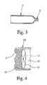
- the duct 5 can comprise a nozzle (restriction) 6 preferably at the outlet, as shown in schematic longitudinal cross section according to Fig. 3 .
- nozzle 6 or any other suitable nozzle arrangement could be used instead or in any other combination with duct 5.
- the dispensing device 1 uses pressurized gas to force the powder 2 through the duct 5 / nozzle 6 to de-agglomerate the powder 2 and/or to generate the spray 3 with fine particle size.
- the dispensing device 1 comprises a means for providing pressurized gas, in the present embodiment an air pump 7 which can preferably be actuated or operated manually as indicated by handle or actuator 8.
- the air pump 7 comprises or is formed by a bellows. But, it could be also a piston-cylinder-arrangement.
- the means for providing pressurized gas can be e.g. a capsule, container or the like containing pressurized or liquefied gas for powering the dispensing device 1, i.e. dispensing the powder 2 as desired.
- the air pump 7 may provide a gas pressure of less than 300 kPa, in particular about 50 to 200 kPa. This is preferably sufficient for operating the dispensing device 1. If liquefied gas or a container with pressurized gas is used, the gas pressures might range from 100 kPa to about 700 kPa. Then, the pressure may be reduced or throttled to the preferred pressure range before supplying the gas to the storage device 4, in particular its storage chamber 10.
- all pressure values mentioned in the present description and the claims are gauge pressures, i.e. pressure differences. All pressure values relate to the pressure in a gas storage such as a container with pressurized or liquefied gas or provided by air pump 7 or relate to the pressures acting in the chambers 10, 14 and/or in the duct 5, at least before a bursting element bursts as mentioned below.
- the dispensing device 1 optionally comprises a regulation or control means 9 as indicated by dashed lines in Fig. 1 and 2 , in particular a valve, a flow restrictor, a capillary tube or the like, for regulating, throttling and/or controlling the gas flow and/or pressure.
- a regulation or control means 9 as indicated by dashed lines in Fig. 1 and 2 , in particular a valve, a flow restrictor, a capillary tube or the like, for regulating, throttling and/or controlling the gas flow and/or pressure.
- the dispensing device 1 or storage device 4 comprises at least one storage chamber 10 containing a single dose of powder 2 that shall be dispensed in one dispensing operation.
- the gas is supplied under pressure to the storage chamber 10 / powder 2 via a gas inlet 11 or the like.
- the inlet 11 is connected or connectable to the means for providing pressurized gas, i.e. in particular the air pump 7, or to the regulation or control means 9.
- the storage chamber 10 is preferably covered or closed by a bursting element 12.
- the bursting element 12 seals the powder 2 in the storage chamber 10 against humidity, air contact or the like.
- the bursting element 12 breaks or bursts if a predetermined pressure difference and/or a predetermined velocity of pressure increase is reached or exceeded (generation of a pressure pulse).
- the bursting element 12 is designed to burst at a pressure difference of less than 300 kPa, more preferably about 50 to 200 kPa, and/or at a pressure pulse with a velocity of pressure increase of more than 0.5 MPa/s, in particular more than 1 MPa/s.
- the bursting element 12 can be made e.g. of plastic or metal. It can be a thin foil, in particular of aluminum, and/or any suitable membrane.
- the bursting element 12 covers in the present invention a cross sectional area of the storage chamber 10 with a mean diameter of at least 5 mm, preferably 7 mm or more.
- the bursting element 12 is pre-scratched or pre-scored or comprises at least one weakened portion to facilitate bursting, as indicated by reference sign 13 in Fig. 4 representing an enlarged perspective view of the storage chamber 10 with the bursting element 12.
- the bursting element 12 is arranged between the respective storage chamber 10 and an associated mixing chamber 14 as shown in Fig. 4 .
- the storage chamber 10 is opened suddenly and the respective dose of powder 2 is dispensed, namely mixed with the gas, forced through the duct 5 and discharged as spray 3 as shown in Fig. 2 .
- the gas generates a respective flow in the storage chamber 10 to force all powder 2 through the outlet, i.e. duct 5.
- the mixing chamber 14 may form an opening space for the optional bursting element 12, so that the bursting element 12 can open sufficiently when it bursts.
- the bursting element 12 can be understood as a pressure sensitive element that opens or allows gas flow through the storage chamber 10 for dispensing the respective powder 2 only if a certain gas pressure (peak pressure) is reached or exceeded.
- peak pressure peak pressure
- the gas expands and the pressure will significantly and/or suddenly drop so that the powder 2 may be mixed with the gas during a pressure pulse in a very effective manner, in particular swirls or eddies support the mixing of gas and powder 2, but the powder 2 will be discharged - in particular forced through the duct 5 - with a lower, comparatively low gas pressure (preferably less than 300 kPa, in particular about 50 to 200 kPa).
- This low gas pressure which is significantly lower than the gas pressures in the prior dispensing devices enables a respectively low discharge velocity and, therefore, a low spray 3 with low propagation velocity.
- the effect of the bursting element 12 can also be realized or supported or even increased by any other suitable pressure sensitive element, in particular by a valve or by a respectively dimensioned reservoir for pressurized gas or the like.
- the sudden expansion of the gas ensures good mixing of the gas and powder 2 in the chambers 10 and 14 and, then, forces the mixture through the duct 5.
- the bursting element 12 is only optional. In some cases, the bursting element 12 is not required. Instead, a sealing element or the like may be provided which can be opened e.g. just before dispensing the powder 2. Alternatively, the outlet end of the duct 5 and/or nozzle 6 could be closed for sealing the powder 2 in the storage chamber 10. Only for the dispensing operation, the duct 5 / nozzle 6 is opened, e.g. by cutting, piercing or the like, and then the powder 2 can be discharged.
- the duct 5 / nozzle 6 could be closed by a suitable plug or cap which seals the powder 2 in the storage chamber 10 during non-use.
- This plug or cap could be removed just before the dispensing operation or opened by the gas pressure during the dispensing operation and have a similar function as the bursting element 12.
- a respective filter could be provided or the plug could be connected in any suitable manner with another part so that the plug can not separate totally.
- the storage device 4 forms the mixing chamber 14 for mixing the gas with the powder 2.
- the chambers 10 and 14 are preferably designed such that the gas can generate swirls or eddies for better mixing the powder 2 with the gas.
- the chambers 10 and 14 are substantially circular in cross section, in particular cylindrical. However, other shapes are also possible.
- the storage device 4 in particular the chambers 10 and 14 are formed with no sharp edges, corners or the like, but have a smooth contour so that the gas can sweep all chamber surfaces to prevent powder 2 accumulating on said surfaces and to ensure or allow complete discharge of the powder 2.
- the gas inlet 11 is located opposite to the powder outlet, i.e. duct 5 and/or nozzle 6, with regard to the axial or outlet direction.
- the storage device 4 may comprise only one storage chamber 10 for a single dose, in this case the storage device 4 is for single dose only, or may comprise multiple storage cavities 10 and, thus, contain multiple doses of powder 2, which can be dispensed subsequently.
- the gas supply provided by the dispensing device 1, in particular air pump 7, can be connected in any suitable manner to the respective storage device 4 or storage chamber 10, in particular to the respective gas inlet 11, preferably only temporarily when required for a dispensing operation.
- a piercing element, connecting element or the like can be fluidically connected with gas inlet 11 / the respective storage chamber 10, in particular by pushing it through a respective sealing element, diaphragm, membrane, wall portion or the like to open or enable gas supply to the respective storage chamber 10.
- Fig. 5 shows in a very schematic sketch another embodiment of the storage device 4 or storage chamber 10, wherein the side walls, in particular the ones of the mixing chamber 14, or the cross section is tapered towards the duct 5 in order to avoid any sharp edges, corners or the like where the powder 2 may remain despite the gas flow.
- the duct 5 has a flat (inner) cross section.
- Fig. 6a to 6c show potential cross sections of the duct 5.
- Fig. 6a shows a substantially rectangular cross section.
- Fig. 6b shows a flat cross section with two opposite straight sides connected by two curved portions.
- Fig. 6c shows an oval or elliptical cross section.
- a cross section is considered to be flat when the ratio of the largest side d1 to the smallest side d2 of the cross section is at least 2.0. Preferably, the ratio is between 3 to 50 and in particular about 5 to 70. It is pointed out that the cross sections shown in Fig. 6 are not in scale.
- the largest side d1 is preferably between 0.5 to 5 mm, in particular 1 to 3 mm. Most preferably, the ratio of the largest side d1 to the (desired) fine particle size (mass mean diameter of the powder particles or drug particles of the spray 3) is less than 500, preferably less than 300, in particular about 30 to 300.
- the smallest side d2 is preferably between 0.05 to 0.5 mm, in particular about 0.07 to 0.25 mm. Most preferably, the ratio of the smallest side d2 to the mass mean (desired) fine particle size (mass mean diameter of the powder particles / drug particles of the spray 3) is less than 50, preferably less than 30, in particular about 3 to 20.
- the length of the duct 5 means the length with the flat cross section.
- the duct 5 can have a larger length, i.e. further portions with another cross sectional shape and/or with a larger cross sectional area so that the influence of these other portions is low on the mixture of gas and powder 2 in comparison to the portion of the duct 5 with the flat cross section.
- the cross section area and/or the shape of the flat cross section may vary over the length of the duct 5 (the portion with the flat cross section).
- the cross sectional area of the duct 5 tapers from the inlet to the outlet or vice versa.
- the duct 5 comprises at least one portion of flat cross section with constant cross section area, i.e. constant diameter and/or shape.
- the length of the duct 5 - i.e. the portion with flat cross section - may be in the range of 3 mm to 80 mm, in particular 5 to 15 mm.
- the duct length is adapted to the mean hydraulic diameter of the duct 5 such that the ratio of the length of the duct 5 to the mean hydraulic diameter is at least 5, in particular about 10, preferably 20 to 60, or more, wherein the hydraulic diameter is defined as the ratio of four cross sectional areas over the duct perimeter.
- the diameter of the preferably circular or cylindrical or conical chambers 10 and 14 depend on the volume of mass of the respective dose of powder 2.
- a single dose may have e.g. 1 to 2 mg (pure drug without carrier) or 2 to 10 mg (blend of drug with carrier, in particular lactose).
- the range of the diameter is preferably 1.5 to 2.5 mm.
- the range of the diameter is preferably between 2 and 5 mm.
- the cross section of the duct 5 varies in a similar manner.
- the smallest side d2 is about 0.07 to 0.1 mm in the first case and about 0.15 to 0.25 mm in the second case.
- the larger (inner) side d1 does not depend so strongly on the powder or particle size.
- it is in the range of about 1 to 2 mm in the first case and 1 to 3 mm in the second case.
- the mean hydraulic diameter of the duct 5 is preferably less than 1 mm, in particular 0.1 mm to 0.6 mm.
- the duct 5 is moulded and/or formed by a flat groove with a cover.
- the dispensing device 1 or storage device 4 may comprise multiple ducts 5 for dispensing simultaneously one dose of powder 2, in particular for increasing the total mass flow or output of dispensed powder 2 so that a desired dose can be discharged or dispensed in a sufficiently short time as desired and/or required.
- Fig. 7 shows another embodiment of the storage device 4 in a schematic representation similar to Fig. 5 .
- two ducts 5 are associated or connected to one storage chamber 10 / mixing chamber 14.
- Fig. 8 shows in a similar representation a further embodiment, wherein the mixing chamber 14 and the ducts 5 are formed by a part separate from the storage device 4 and the storage chamber 10.
- This separate part can form a cover 15 or the like and is placed in contact with the storage device 4 or over the bursting element 12 before gas is supplied and the powder 2 is dispensed.
- the separate part may comprise only one duct 5 or multiple ducts 5, in particular two ducts 5 as shown. Multiple ducts 5 have the advantage that even if one duct 5 is blocked, the dispensing device 1 still works, e.g. powder 2 can be still dispensed.
- Fig. 9 shows another embodiment similar to Fig. 7 , but with a multiplicity of ducts 5 which are preferably arranged one directly at the side of the other so that a filter is formed wherein the filter pores are formed by the ducts 5.
- Fig. 10 shows a different embodiment of the storage device 4 without bursting element 12.
- the storage chamber 10 is closed by a sealing element or the like that can be opened, e.g. pierced, by the duct 5 (as shown in Fig. 10 ) or in any other suitable manner and connected with the duct 5 and/or nozzle 6.
- a separate mixing chamber 14 is not provided.
- the storage chamber 10 has a volume that is not completely filled by the powder 2 so that the gas and the powder 2 can be mixed directly within the storage chamber 10, i.e. the storage chamber 10 also forms the mixing chamber.
- the direction of gas supply and the outlet of the mixing chamber 14 do not have to be transversal as it is the case in the previous embodiments.
- the gas inlet direction and the outlet direction from the storage chamber 10 may be in parallel planes, but preferably offset to each other and/or parallel to each other.
- Fig. 10 shows the dispensing device 1 or storage device 4 with already inserted or connected duct 5. However, in Fig. 5 and 7 to 10 the air supply is not yet connected to the storage chamber 10 or its inlet 11.
- Fig. 11 shows a longitudinal sectional view of another embodiment of the duct 5.
- the dispensing device 1 or in particular the duct 5 comprises a means for slowing down the outlet velocity and, thus, the propagation velocity of the spray 3.
- the means for slowing down the velocity is a diffuser 16 located at or connected to the exit of the duct 5.
- the diffuser 16 has an appropriate angle to decrease the outlet velocity.
- the duct 5 can also comprise a tapered inlet section 17 as shown in Fig. 12 in a longitudinal section view similar to Fig. 11 .
- the tapered cross section 17 can have any suitable inner contour and may be curved to avoid any sharp edges at the transition to the taper section 17 or from the tapered section 17 to the duct 5.
- This tapered inlet section 17 may be used for all embodiments with a duct 5 or multiple ducts 5. This applies also for the embodiment according to Fig. 11 , i.e. the means for slowing down the outlet velocity.
- Fig. 13 shows in a schematic sectional view another duct arrangement with another means for slowing down the velocity which forms a multiple powder jet spray impinging means 18.
- the means 18 forms multiple - at least two - powder spray jets P which impinge, i.e. hit each other as indicated in Fig. 13 .
- the duct 5 divides into two sections 5a and 5b that are designed such that the openings or outlets are inclined to each other so that the powder jets P ejecting from the portions 5a and 5b are inclined to each other and impinge.
- a flow divider 19 or any guiding means can be located in the flow path to form the at least two sections 5a and 5b of the duct 5 as shown in Fig. 13 .
- the impinging angle ⁇ between the powder jets P is between 30° to 180°, preferably at least 90°, in particular about 90° to 150°.
- the impinging of the powder jets P results in a decrease of the velocity of the spray 3 and/or in a de-agglomeration of the powder 2 and/or in separation of drug particles from a carrier and/or in better focusing of the spray 3.
- These effects depend on the impinging angle ⁇ .
- a larger impinging angle ⁇ results in better effects.
- an impinging angle ⁇ of 90° and more is possible and preferred. These angles also apply for the following embodiments.
- the duct 5 is preferably at least tangentially connected to the storage chamber 10 / mixing chamber 14 in the embodiment shown in Fig. 13 .
- the duct 5 is connected to the mixing chamber 14 at one axial end of the cylindrical chamber 14, and the gas inlet 11 is connected to the other axial end of the chamber 10.
- the gas inlet 11 is connected also tangentially to the storage chamber 10, such that swirls are generated when entering the gas with a swirl direction supporting discharge of the mixture of gas and powder 2 through the duct 5 which connects tangentially to the rotational direction of the swirl.
- Fig. 14 shows in a schematic sectional view another embodiment of the powder jet impinging means 18.
- two or more ducts 5 comprise inclined or outlet sections 5c which are inclined to each other so that the powder jets P ejected from outlet sections 5c impinge with each other.
- Fig. 15 shows in a schematic sectional view a further embodiment of the powder spray jet impinging means 18.
- the ducts 5 are generally inclined to each other to achieve the designed impingement of the powder jets P.
- the optional flow divider 19 may be located within the mixing chamber 14 or storage chamber 10 to ensure a desired flow and mixture of the gas with the powder 2.
- Fig. 13 to 15 are also suitable for impinging more than two powder jets P.
- multiple other arrangements with similar effects are possible.
- cross sections of the duct sections 5a to 5c are preferably not flat but can have any suitable cross sectional shape.
- the duct 5 can also be used as a reservoir (storage chamber 10) for the powder 2.
- the separate storage chamber 10 and mixing chamber 14 are not required.
- the duct 5 is designed to enable sufficient mixing of the gas with the powder 2 and sufficient de-agglomeration of the powder 2.
- the gas inlet 11 or the gas supply comprises a smaller cross sectional area than the duct 5 or nozzle 6 so that the gas flow is determined by the inlet and not by the outlet side, i.e. not by the duct 5 or nozzle 6, during dispensing.
- the pressure reaches a peak value at the beginning of the dispensing operation just before the bursting element 12 or another pressure sensitive element opens. With opening the bursting element 12 or any other pressure sensitive element, the sudden pressure decrease results in that the gas and powder 2 mix very well and quickly in the storage chamber 10 and mixing chamber 14.
- the mixture of gas and powder 2 is forced by the already lower gas pressure through the duct 5 and/or any other suitable outlet such as nozzle 6, wherein the gas flow is controlled during this phase at least mainly by the cross section of the gas inlet 11 or any other restriction stream up of gas inlet 11. Due to the comparatively low gas pressure for discharging the powder 2 through duct 5 and/or nozzle 6 a low discharge velocity and, thus, a low propagation velocity of the spray 3 can be achieved. A good de-agglomeration of the powder 2 can be achieved by the flat cross section of the duct 5 even with a comparatively low discharge velocity in the duct 5.
- the means for slowing down the propagation velocity of the spray 3, in particular the diffuser 16 or the powder jet impinging means 18, can be used to further decrease the propagation velocity of the spray 3.
- the spray 3 has a mean velocity (taken 10 cm from the outlet / mouthpiece) of less than 2 m/s, in particular less than 1 m/s.
- the mean duration of the spray 3 is at least 0.2 or 0.3 s, in particular about 0.5 to 2 s.
- Fig. 16 shows another embodiment of the dispensing device 1 or storage device 4 with multiple storage cavities 10.
- the storage device 4 is a circular disc, wherein the storage cavities 10 are positioned along the perimeter of the disc spaced to each other, preferably with a radial orientation so that the associated mixing chambers 14 are located radially outwardly and/or adjacent to the storage cavities 10 and separated by respective bursting elements 12.
- the disc may be of molded plastic or made in any other suitable manner or of any other suitable material.
- the storage cavities 10 and/or the mixing chambers 14 can have a cylindrical or conical form.
- the bursting elements 12 are preferably disc-like and secured for example by conical holders 20 or the like in place covering the respective storage chamber 10 preferably radially.
- the holders 20 may be secured e.g. by an outerring 21 or the like.
- Fig. 16 shows the disc without an upside cover or with a transparent cover that covers and closes the storage cavities 10 and the mixing chambers 14 from above in the drawing.
- the gas inlets 11 and the duct 5 or other suitable outlet ports are formed in the cover and/or the disc or inserted just for the dispensing operation as depicted in Fig. 16 .
- respective inlet ports and/or ports are formed in the disc.
- the gas inlet 11 or a respective connection element and the duct 5 or a respective connection element are pushed through the sealing cover in the respective ports.
- the gas supply is open or the air pump 7 is actuated, the bursting element 12 bursts and the gas pressure forces the gas powder mixture through the connected duct 5 and/or nozzle 6. Afterwards or just before the next dispensing operation, the disc is rotated to the next position.
- Fig. 17 shows a partial axial section of a similar dispensing device 1 or storage device 4 with multiple powder reservoirs (storage cavities 10). Preferably, it's a circular or cylindrical arrangement with some layers or discs placed axially one above the other.
- the powder 2 is completely from atmospheric humidity (this applies to each embodiment) and, thus kept dry.
- the storage cavities 10 may be formed in a first disc 23, e.g. made of plastic.
- the first sealing layer 22 is preferably bonded to the first disc 23.
- a second sealing layer 24 is bonded to the first disc 23 and covers the storage cavities 10 from the other side and, thus, forms the bursting elements 12.
- the second layer 24 is preferably also a foil, in particular a thin coated aluminum foil or the like, and acts as a second humidity barrier for isolating the powder 2 in the storage cavities 10.
- the second sealing layer 24, in turn, may be covered by second disc 25 with recesses forming the respective mixing chambers 14 located axially above the associated storage cavities 10 separated by the second sealing layer 24.
- a filter layer 26 or any other suitable cover may be bonded on the second disc for covering the mixing chambers 24.
- This layer 26 or cover may directly form the ducts 5, the nozzle 6 or any other suitable outlet means, such as a mesh, or may be a support and/or seal for an outlet element, such as the duct 5, that can be inserted into the respective mixing chamber 14 through layer 26 for the respective dispensing operation.
- a third disc 27 may be bonded to the first sealing layer 22 on the opposite to first disc 23.
- This third disc 27 can be made e.g. or plastic and comprise recesses or the like forming the gas inlets 11. These gas inlets 11 are preferably offset with respect to the storage cavities 10 so that transversal or tangential gas supply is possible instead of an axial gas supply.
- Soft sealing elements 28 are preferably arranged in the first disc 23 opposite to the gas inlet 11.
- a gas supply element 29 or any other suitable element is pushed into one gas inlet 11 and through the first sealing layer 22 until the corresponding soft sealing element 28 is sufficiently deformed to allow ingress of gas into the associated (adjacent) storage chamber 10.
- the gas supply is opened, e.g. regulation or control means 9, or the air pump 7 is actuated and the pressure reaches a peak level, the respective bursting element 12 formed by the second layer 24 and the gas and powder mixture is forced through filter layer 26 or any other suitable output element, such as a duct 5 or nozzle 6.
- the third disc 27 is optional.
- the gas inlets 11 could be formed in the first disc 23, in particular between the first sealing layer 22 and the soft sealing element 28, or omitted.
- the dispensing device 1 or storage device 4 comprises a base 30 with at least one storage chamber 10 or multiple storage chambers 10.
- the storage chambers 10 are preferably arranged in a row, wherein the base 30 may form a stripe, or along a circle, wherein the holder 30 may form a disc.
- a first sealing layer 22 covers the storage chamber(s) 10 and acts as a humidity barrier so that the powder 2 is isolated from the atmosphere and kept dry.
- the gas supply element 29 is pushed - for example axially - through the base 30 or through a side wall or through the sealing layer 22 into the respective storage chamber 10 as shown in Fig. 18a .
- the layer 22 forming a bursting element 12 bursts and the powder 2 is discharged as shown in Fig. 18b .
- the powder 2 could be discharged into a cover 15 with at least one duct 5 as shown in Fig. 8 , if that cover 15 is placed on the layer 22 above the respective storage chamber 10 before the gas is supplied.
- Fig. 19 shows another embodiment of the dispensing device 1 in a very schematic sectional view.
- the storage device 4 is a preferably disc-like cartridge, container, blister or the like with multiple storage chambers.
- the storage device 4 can be rotated or indexed stepwise so that the powder 2 can be dispensed from the storage chambers 10 one after the other.
- the gas may be supplied axially, and the mixture of gas and powder 2 may be dispensed radially, in particular into a mouthpiece 31 for a user or patient (not shown).
- the powder 2 is dispensed through at least one duct 5 and/or a nozzle 6 which is located within the mouthpiece 31 and, in particular, set back with regard to the opening of the mouthpiece 31. This applies preferably also to the dispensing device 1 shown in Fig. 1 and 2 .
- Fig. 20 shows a further embodiment of the storage device 4 with multiple storage chambers 10 in a circular or disc-like arrangement which could be used in the dispensing device 1 according to Fig. 19 .
- the storage device 4 comprises ducts 5 which may be oriented radially as shown in Fig. 20 .
- This arrangement has the advantage that each dose of powder 2 may be dispensed through a separate, i.e. unused duct 5.
- a bursting element 12 may be arranged between each storage chamber 10 and the respective duct 5 as shown in Fig. 20 .
- a mixing chamber 14 may be associated to each storage chamber 10, in particular between the bursting element 12 and the duct 5, if desired.
- each storage chamber 10 may also form the mixing chamber as already explained with respect to the embodiment according to Fig. 10 . It is pointed out, that the features of the other embodiments, such as the powder jet impinging means 18 or the like, can also be realized in the embodiment according to Fig. 20 .
- Gas can be supplied in particular axially or tangentially into the storage chambers 10, e.g. by inserting a respective gas supply element 29 or the like.
- the present invention in particular the dispensing device 1 and/or the storage device 4, can be used for dispensing one drug, a blend of drugs or at least two or three separate drugs.
- the separate drugs are stored in separate storage chambers 10 and, during the dispensing operation, the drugs are mixed either in a common mixing chamber 14 or in separate mixing chambers 14 or in their respective storage chambers 10 with the gas.
- the separate drugs can be discharged through a common duct 5 nozzle 6 or through separate ducts 5 nozzles 6.
- the separate drugs will be mixed after leaving the separate ducts 5 / nozzles 6 or in the mouthpiece 31 or in any other suitable (additional) mixing chamber.
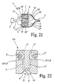
- Fig. 21 shows a further embodiment of the dispensing device 1 / storage device 4 with at least two or three separate powders 2, i.e. separate drugs, which are stored in separate storage chambers 10', 10" and 10 "', which may be formed by intermediate walls 32 and each storage chamber can be covered by an optional bursting element 12', 12" or 12"'.
- Pressurized gas can be supplied from a common means for providing pressurized gas, in particular air pump 7 and/or regulation of control means 9, via separate gas inlets 11', 11" and 11"'. Alternatively, separate gas supplies can be provided.
- the respective bursting elements 12', 12" and 12"' burst and the separate drugs / powders 2', 2" and 2"' can mix in the common mixing chamber 14 and the mixture is dispensed together through at least one common duct 5, nozzle 6 or the like as spray 3 (not shown).
- the bursting elements 12', 12" and 12"' can be formed from one common layer of material, in particular foil or the like.
- the central storage chamber 10" could be encompressed by at least one, preferably annular storage chamber.
- wall 32 can be cylindrical and the reference signs 10' and 10"' denote the same annular storage chamber resulting in only two different drugs / powders 2 in the two separate storage chambers (central chamber and annular chamber) in the embodiment of fig. 21 .
- reference signs 12' and 12"' relate to the same annular bursting element covering the annular chamber.
- Fig. 22 shows in a schematic sectional view another embodiment of the dispending device 1 and storage device 4.
- Two different drugs / powders 2' and 2" are contained in separate storage / mixing chambers 10'/14' and 10"/14", respectively. Gas can be supplied via separate gas inlets 11' and 11" to the chambers 11'/14' and 10"/14", respectively.
- the powders 2' and 2" can be dispensed and de-agglomerated by means of separate ducts 5' and 5" or (not shown) separate nozzles or the like.
- the powder jets P of the separate or different drugs / powders 2' and 2" ejecting from the separate ducts 5' and 5" are preferably impinged for mixing the separate drugs / powders 2' and 2" just when forming the spray 3 (not shown).
- the powder jet impinging means 18 mixes the separate drugs / powders 2' and 2", but can also serve to slow down the propagation velocity of the spray 3 and/or to support de-agglomeration of the powders 2' and 2" or of separating the respective drugs from carriers.
- Example 1 A blend of 90.0 % by weight of lactose 200, of 9.7 % by weight of fine lactose, and of 0.3 % by weight of Tiotropium was used.
- the mean particle diameter of lactose 200 was about 45 ⁇ m, of fine lactose about 4 ⁇ m and ofTiotropium about 4 ⁇ m.
- About 5.5 mg of the blend was positioned as powder 2 in the storage and mixing chamber 10 / 14 which had a substantially cylindrical shape with a diameter of 3 mm and an axial length of 3 mm. 5 ml of compressed air was supplied via the gas inlet having an inlet orifice of 0.5 mm into the chamber 10/14 with a gauge pressure of about 100 kPa.
- the powder 2 was dispensed via duct 5 of substantially rectangular cross section having a smallest side of about 0.18 mm and a largest side of about 1.5 mm.
- the duct 5 divided into two duct sections 5a and 5b (in particular as shown in Fig. 13 ), wherein each section had a substantially rectangular cross section with a smallest side of about 0.18 mm and the largest side of about 0.75 mm.
- the total length of the duct 5 including the sections 5a, 5b was about 8 mm.
- the result was that 100 % of the metered mass, i.e. all powder 2 in chamber 10 / 14, was dispensed. Approximately 50% of both diameter mean and mass mean fine fraction was measured on a Anderson Cascade Impactor at both 30 and 60 l/min.
- Example 2 About 1.5 mg of Fenoterol with a mean particle diameter of 4 ⁇ m was positioned as powder 2 in the storage and mixing chamber 10 / 14 which had a substantially cylindrical shape with a diameter of 2 mm and an axial length of 2 mm, 5 ml of compressed air was supplied via the gas inlet having an inlet orifice of 0.5 mm into the chamber 10/14 with a gauge pressure of about 150 kPa.
- the powder 2 was dispensed via a duct 5 of substantially rectangular cross section having a smallest side of 0.075 mm and a largest side of 1.5 mm.
- the duct 5 divided into two duct sections 5a and 5b (in particular as shown in fig.
- each section had a substantially rectangular cross section with a smallest side of about 0.075 mm and the largest side of about 0.75 mm.
- the total length of the channel including the sections 5a, 5b was about 8 mm. The result was that 100 % of the metered mass, i.e. all powder 2 in chamber 10 / 14, was dispensed. Approximately 45% of both diameter mean and mass mean fine fraction was measured on a Anderson Cascade Impactor at both 30 and 60 l/min.
Landscapes
- Health & Medical Sciences (AREA)
- Engineering & Computer Science (AREA)
- Animal Behavior & Ethology (AREA)
- Veterinary Medicine (AREA)
- Public Health (AREA)
- General Health & Medical Sciences (AREA)
- Life Sciences & Earth Sciences (AREA)
- Heart & Thoracic Surgery (AREA)
- Hematology (AREA)
- Biomedical Technology (AREA)
- Anesthesiology (AREA)
- Bioinformatics & Cheminformatics (AREA)
- Pulmonology (AREA)
- Pharmacology & Pharmacy (AREA)
- Chemical & Material Sciences (AREA)
- Medicinal Chemistry (AREA)
- Containers And Packaging Bodies Having A Special Means To Remove Contents (AREA)
- Nozzles (AREA)
- Medicinal Preparation (AREA)
Applications Claiming Priority (5)
| Application Number | Priority Date | Filing Date | Title |
|---|---|---|---|
| GB0422106A GB0422106D0 (en) | 2004-10-06 | 2004-10-06 | Powder dispensing means |
| GB0425289A GB0425289D0 (en) | 2004-11-17 | 2004-11-17 | Powder dispensing means |
| GB0427552A GB0427552D0 (en) | 2004-12-15 | 2004-12-15 | Powder dispensing means |
| GB0509108A GB0509108D0 (en) | 2005-05-04 | 2005-05-04 | Powder dispensing means |
| EP05797355A EP1819388A2 (fr) | 2004-10-06 | 2005-10-06 | Dispositif de distribution, dispositif de stockage et procede de distribution de poudre |
Related Parent Applications (2)
| Application Number | Title | Priority Date | Filing Date |
|---|---|---|---|
| EP05797355.4 Division | 2005-10-06 | ||
| EP05797355A Division EP1819388A2 (fr) | 2004-10-06 | 2005-10-06 | Dispositif de distribution, dispositif de stockage et procede de distribution de poudre |
Publications (2)
| Publication Number | Publication Date |
|---|---|
| EP2277577A1 true EP2277577A1 (fr) | 2011-01-26 |
| EP2277577B1 EP2277577B1 (fr) | 2018-03-14 |
Family
ID=35457812
Family Applications (2)
| Application Number | Title | Priority Date | Filing Date |
|---|---|---|---|
| EP05797355A Withdrawn EP1819388A2 (fr) | 2004-10-06 | 2005-10-06 | Dispositif de distribution, dispositif de stockage et procede de distribution de poudre |
| EP10010487.6A Expired - Lifetime EP2277577B1 (fr) | 2004-10-06 | 2005-10-06 | Dispositif de distribution de poudre |
Family Applications Before (1)
| Application Number | Title | Priority Date | Filing Date |
|---|---|---|---|
| EP05797355A Withdrawn EP1819388A2 (fr) | 2004-10-06 | 2005-10-06 | Dispositif de distribution, dispositif de stockage et procede de distribution de poudre |
Country Status (12)
| Country | Link |
|---|---|
| US (2) | US9283335B2 (fr) |
| EP (2) | EP1819388A2 (fr) |
| JP (1) | JP4908419B2 (fr) |
| KR (1) | KR20070073865A (fr) |
| CN (1) | CN101785892B (fr) |
| AU (1) | AU2005291427A1 (fr) |
| CA (1) | CA2581044C (fr) |
| EA (1) | EA200700743A1 (fr) |
| IL (1) | IL182402A0 (fr) |
| MX (1) | MX2007004106A (fr) |
| NO (1) | NO20071541L (fr) |
| WO (1) | WO2006037636A2 (fr) |
Cited By (4)
| Publication number | Priority date | Publication date | Assignee | Title |
|---|---|---|---|---|
| EP3052168B1 (fr) | 2013-10-02 | 2019-11-27 | Cook Medical Technologies LLC | Agents thérapeutiques à administrer à l'aide d'un cathéter et d'une source de pression |
| US12226568B2 (en) | 2020-06-05 | 2025-02-18 | Cook Medical Technologies Llc | Medical scopes for delivering therapeutic agents |
| US12496429B2 (en) | 2022-10-18 | 2025-12-16 | Cook Medical Technologies Llc | Systems and methods for delivering pressurized fluid to a target site alone or in conjunction with therapeutic agents |
| US12543936B2 (en) | 2021-07-14 | 2026-02-10 | Cook Medical Technologies Llc | Systems and methods for preventing clogging of a delivery system |
Families Citing this family (129)
| Publication number | Priority date | Publication date | Assignee | Title |
|---|---|---|---|---|
| US9006175B2 (en) | 1999-06-29 | 2015-04-14 | Mannkind Corporation | Potentiation of glucose elimination |
| GB0128148D0 (en) * | 2001-11-23 | 2002-01-16 | Innovata Biomed Ltd | Assembly |
| WO2003080149A2 (fr) | 2002-03-20 | 2003-10-02 | Mannkind Corporation | Appareil d'inhalation |
| US7638138B2 (en) * | 2003-02-21 | 2009-12-29 | Translational Research, Ltd. | Compositions for nasal administration of pharmaceuticals |
| AU2003220808B2 (en) | 2003-03-27 | 2008-08-21 | Bioactis Limited | Powder medicine applicator for nasal cavity |
| WO2006016530A1 (fr) * | 2004-08-10 | 2006-02-16 | Translational Research, Ltd. | Composition transnasale dont l’action est immédiate et l’absorbabilité est élevée |
| PL1786784T3 (pl) | 2004-08-20 | 2011-04-29 | Mannkind Corp | Kataliza syntezy diketopiperazyn |
| KR101644250B1 (ko) | 2004-08-23 | 2016-07-29 | 맨카인드 코포레이션 | 약물 전달용 디케토피페라진염, 디케토모르포린염 또는 디케토디옥산염 |
| CN104324362B (zh) | 2005-09-14 | 2018-04-24 | 曼金德公司 | 以提高活性试剂对结晶微粒表面的亲和力为基础的药物配制方法 |
| EP1795221A1 (fr) * | 2005-12-02 | 2007-06-13 | Boehringer Ingelheim Pharma GmbH & Co. KG | Appareil pour distribuer, stocker, et méthode pour distribuer une formulation |
| IN2015DN00888A (fr) | 2006-02-22 | 2015-07-10 | Mannkind Corp | |
| JP2009533104A (ja) * | 2006-04-13 | 2009-09-17 | ベーリンガー インゲルハイム マイクロパーツ ゲゼルシャフト ミット ベシュレンクテル ハフツング | 計量投与器具 |
| USD620556S1 (en) * | 2006-04-26 | 2010-07-27 | Chapin Manufacturing, Inc. | Combined sprayer tank cap and pressure relief valve |
| DE102006043637A1 (de) | 2006-05-18 | 2007-11-22 | Boehringer Ingelheim Pharma Gmbh & Co. Kg | Zerstäuber |
| EP1867357A1 (fr) * | 2006-06-13 | 2007-12-19 | TrendTech A/S | Inhalateur |
| JP2008049127A (ja) * | 2006-07-24 | 2008-03-06 | Canon Inc | 吸入装置 |
| DE102006047667B3 (de) * | 2006-09-28 | 2008-04-24 | Ing. Erich Pfeiffer Gmbh | Inhalationsvorrichtung |
| US8337817B2 (en) | 2006-12-26 | 2012-12-25 | Shin Nippon Biomedical Laboratories, Ltd. | Preparation for transnasal application |
| EP1992374A1 (fr) * | 2007-05-16 | 2008-11-19 | Boehringer Ingelheim Pharma GmbH & Co. KG | Dispositif distributeur |
| EP1992372A1 (fr) | 2007-05-16 | 2008-11-19 | Boehringer Ingelheim Pharma GmbH & Co. KG | Dispositif de distribution |
| EP1992376A1 (fr) * | 2007-05-16 | 2008-11-19 | Boehringer Ingelheim Pharma GmbH & Co. KG | Dispositif distributeur |
| EP1992378A1 (fr) * | 2007-05-16 | 2008-11-19 | Boehringer Ingelheim Pharma GmbH & Co. KG | Dispositif distributeur |
| EP1992375A1 (fr) * | 2007-05-16 | 2008-11-19 | Boehringer Ingelheim Pharma GmbH & Co. KG | Dispositif distributeur |
| EP1992377A1 (fr) | 2007-05-16 | 2008-11-19 | Boehringer Ingelheim Pharma GmbH & Co. KG | Dispositif distributeur |
| EP1992379A1 (fr) | 2007-05-16 | 2008-11-19 | Boehringer Ingelheim Pharma GmbH & Co. KG | Dispositif distributeur |
| EP1992381A1 (fr) * | 2007-05-16 | 2008-11-19 | Boehringer Ingelheim Pharma GmbH & Co. KG | Dispositif distributeur |
| EP1992373A1 (fr) | 2007-05-16 | 2008-11-19 | Boehringer Ingelheim Pharma GmbH & Co. KG | Dispositif distributeur |
| EP1992380A1 (fr) * | 2007-05-16 | 2008-11-19 | Boehringer Ingelheim Pharma GmbH & Co. KG | Dispositif distributeur |
| US8528544B2 (en) * | 2007-05-30 | 2013-09-10 | Canon Kabushiki Kaisha | Inhaler |
| JP5328776B2 (ja) | 2007-06-01 | 2013-10-30 | ベーリンガー インゲルハイム インターナショナル ゲゼルシャフト ミット ベシュレンクテル ハフツング | 小出し器具 |
| EP2042208A1 (fr) | 2007-09-25 | 2009-04-01 | Boehringer Ingelheim Pharma GmbH & Co. KG | Dispositif distributeur |
| US8545457B2 (en) * | 2007-11-08 | 2013-10-01 | Terumo Kabushiki Kaisha | Sprayer |
| EP2534957B1 (fr) | 2007-12-14 | 2015-05-27 | AeroDesigns, Inc | Administration de produits sous forme d'aérosols |
| EP2077132A1 (fr) * | 2008-01-02 | 2009-07-08 | Boehringer Ingelheim Pharma GmbH & Co. KG | Dispositif distributeur, dispositif de stockage et procédé pour la distribution d'une formulation |
| US8485180B2 (en) | 2008-06-13 | 2013-07-16 | Mannkind Corporation | Dry powder drug delivery system |
| ES2929343T3 (es) | 2008-06-13 | 2022-11-28 | Mannkind Corp | Inhalador de polvo seco accionado por aspiración para la administración de fármacos |
| KR101628410B1 (ko) | 2008-06-20 | 2016-06-08 | 맨카인드 코포레이션 | 흡입 활동에 관한 실시간 프로파일링을 위한 대화형 장치 및 방법 |
| ITMI20081315A1 (it) * | 2008-07-18 | 2010-01-19 | Iph Establishment | Dispositivo per rimuovere secrezioni polmonari |
| TWI614024B (zh) | 2008-08-11 | 2018-02-11 | 曼凱公司 | 超快起作用胰島素之用途 |
| US8314106B2 (en) | 2008-12-29 | 2012-11-20 | Mannkind Corporation | Substituted diketopiperazine analogs for use as drug delivery agents |
| DK2405963T3 (da) | 2009-03-11 | 2013-12-16 | Mannkind Corp | Apparat, system og fremgangsmåde til at måle modstand i en inhalator |
| WO2010105776A1 (fr) | 2009-03-17 | 2010-09-23 | Boehringer Ingelheim International Gmbh | Dispositif de distribution, dispositif de stockage et procédé de distribution d'une préparation |
| EP2414560B1 (fr) | 2009-03-31 | 2013-10-23 | Boehringer Ingelheim International GmbH | Procédé de revêtement d'une surface d'un composant |
| WO2010131486A1 (fr) * | 2009-05-15 | 2010-11-18 | Shin Nippon Biomedical Laboratories, Ltd. | Compositions pharmaceutiques intranasales avec pharmacocinétique améliorée |
| JP5763053B2 (ja) | 2009-05-18 | 2015-08-12 | ベーリンガー インゲルハイム インターナショナル ゲゼルシャフト ミット ベシュレンクテル ハフツング | アダプタ、吸入器具及びアトマイザ |
| CN104721825B (zh) | 2009-06-12 | 2019-04-12 | 曼金德公司 | 具有确定比表面积的二酮哌嗪颗粒 |
| US20120103332A1 (en) * | 2009-07-13 | 2012-05-03 | Meadwestvaco Calmar Gmbh | Powder Delivery Devices and Methods of Using the Same |
| WO2011013003A2 (fr) * | 2009-07-31 | 2011-02-03 | Shin Nippon Biomedical Laboratories, Ltd. | Granisétron pour administration intranasale et applicateur nasal |
| WO2011056889A1 (fr) | 2009-11-03 | 2011-05-12 | Mannkind Corporation | Appareil et méthode de simulation d'efforts d'inhalation |
| AU2010319681B2 (en) * | 2009-11-13 | 2015-12-17 | Merck Sharp & Dohme Llc | Drug products, dry powder inhalers and polyflux collider arrangements |
| US10016568B2 (en) | 2009-11-25 | 2018-07-10 | Boehringer Ingelheim International Gmbh | Nebulizer |
| WO2011064163A1 (fr) | 2009-11-25 | 2011-06-03 | Boehringer Ingelheim International Gmbh | Nébuliseur |
| BR112012012475B1 (pt) | 2009-11-25 | 2020-03-03 | Boehringer Ingelheim International Gmbh | Nebulizador |
| US10173019B2 (en) | 2009-12-26 | 2019-01-08 | Inspiro Medical Ltd. | Dry powder delivery device |
| CN102946770A (zh) * | 2010-06-16 | 2013-02-27 | 雀巢产品技术援助有限公司 | 带有改进的粉末定量给料系统的饮料分配器 |
| IL223742A (en) | 2010-06-21 | 2016-06-30 | Mannkind Corp | A dry powder inhaler and preparation for it |
| WO2011160932A1 (fr) | 2010-06-24 | 2011-12-29 | Boehringer Ingelheim International Gmbh | Nébuliseur |
| JP6339371B2 (ja) | 2011-03-03 | 2018-06-06 | インペル ニューロファーマ インコーポレイテッド | 経鼻薬物送達デバイス |
| EP2694220B1 (fr) | 2011-04-01 | 2020-05-06 | Boehringer Ingelheim International GmbH | Appareil médical pourvu d'un récipient |
| AU2012236150B2 (en) | 2011-04-01 | 2016-03-31 | Mannkind Corporation | Blister package for pharmaceutical cartridges |
| CN103619485B (zh) * | 2011-05-09 | 2017-08-08 | 英倍尔药业股份有限公司 | 用于鼻腔药物递送的喷嘴 |
| US9827384B2 (en) | 2011-05-23 | 2017-11-28 | Boehringer Ingelheim International Gmbh | Nebulizer |
| WO2012174472A1 (fr) | 2011-06-17 | 2012-12-20 | Mannkind Corporation | Microparticules de dicétopipérazine de capacité élevée |
| BR112014009686A2 (pt) | 2011-10-24 | 2018-08-07 | Mannkind Corp | composição analgésica inalável, pó seco e método para tratar dor |
| BR112014014594B1 (pt) * | 2011-12-16 | 2021-02-17 | Indosys Limited | dispositivo de liberação de medicamento seco em pó |
| US10463815B2 (en) | 2012-02-21 | 2019-11-05 | Respira Therapeutics, Inc. | Inhaler to deliver substances for prophylaxis or prevention of disease or injury caused by the inhalation of biological or chemical agents |
| WO2013152894A1 (fr) | 2012-04-13 | 2013-10-17 | Boehringer Ingelheim International Gmbh | Pulvérisateur comprenant des moyens de détrompage |
| CN104619369B (zh) | 2012-07-12 | 2018-01-30 | 曼金德公司 | 干粉药物输送系统和方法 |
| KR101313993B1 (ko) * | 2012-07-24 | 2013-10-01 | 한국화학연구원 | 약물 흡입 장치 |
| KR101373981B1 (ko) * | 2012-07-24 | 2014-03-12 | 한국화학연구원 | 약물 흡입 장치 |
| US10159644B2 (en) | 2012-10-26 | 2018-12-25 | Mannkind Corporation | Inhalable vaccine compositions and methods |
| US8920364B2 (en) | 2013-02-28 | 2014-12-30 | Medtronic Xomed, Inc. | Biomaterial delivery device |
| US8845578B2 (en) | 2013-02-28 | 2014-09-30 | Medtronic Xomed, Inc. | Biomaterial delivery device |
| AU2014228415B2 (en) | 2013-03-15 | 2018-08-09 | Mannkind Corporation | Microcrystalline diketopiperazine compositions and methods |
| EP2991713B1 (fr) * | 2013-04-28 | 2019-06-19 | Impel Neuropharma Inc. | Récipient à dose unitaire médical |
| MX375448B (es) | 2013-07-18 | 2025-03-06 | Mannkind Corp | Composiciones farmacéuticas en polvo seco estables al calor y métodos. |
| US11446127B2 (en) | 2013-08-05 | 2022-09-20 | Mannkind Corporation | Insufflation apparatus and methods |
| JP6643231B2 (ja) | 2013-08-09 | 2020-02-12 | ベーリンガー インゲルハイム インターナショナル ゲゼルシャフト ミット ベシュレンクテル ハフツング | ネブライザ |
| ES2836977T3 (es) | 2013-08-09 | 2021-06-28 | Boehringer Ingelheim Int | Nebulizador |
| WO2015062420A1 (fr) * | 2013-10-28 | 2015-05-07 | 浙江三创生物科技有限公司 | Procédé et appareil d'injection de poudre |
| GB2520958A (en) * | 2013-12-04 | 2015-06-10 | Team Consulting Ltd | An apparatus and method for providing aerosolized powder delivery |
| WO2015127258A2 (fr) * | 2014-02-21 | 2015-08-27 | Respira Therapeutics, Inc. | Inhalateur de poudre, système et procédés |
| NO2709641T3 (fr) | 2014-03-10 | 2018-05-12 | ||
| US10307464B2 (en) | 2014-03-28 | 2019-06-04 | Mannkind Corporation | Use of ultrarapid acting insulin |
| SE538399C2 (sv) * | 2014-04-03 | 2016-06-14 | Iconovo Ab | Torrpulverinhalator |
| CN116036425A (zh) | 2014-05-07 | 2023-05-02 | 勃林格殷格翰国际有限公司 | 喷雾器、指示器装置及容器 |
| WO2015169430A1 (fr) | 2014-05-07 | 2015-11-12 | Boehringer Ingelheim International Gmbh | Nébuliseur |
| IL247927B (en) | 2014-05-07 | 2022-09-01 | Boehringer Ingelheim Int | Container, a device that turns a liquid into a fine spray and use |
| JP6474062B2 (ja) * | 2014-07-03 | 2019-02-27 | 株式会社エアーサーフ | 粉体噴霧器 |
| WO2016014153A1 (fr) * | 2014-07-23 | 2016-01-28 | Microdose Therapeutx, Inc. | Nébuliseur de poudre sèche |
| US10561806B2 (en) | 2014-10-02 | 2020-02-18 | Mannkind Corporation | Mouthpiece cover for an inhaler |
| CN107427650A (zh) | 2015-01-14 | 2017-12-01 | 瑞必治公司 | 粉末分散方法和装置 |
| US20180056022A1 (en) * | 2015-03-21 | 2018-03-01 | James Zhou Liu | Hand-actuated dry powder inhaler and its use |
| ES2932770T3 (es) * | 2015-05-08 | 2023-01-26 | Iconovo Ab | Inhalador de polvo seco |
| US9981233B2 (en) * | 2015-07-24 | 2018-05-29 | Phillip Phung-I HO | Portable mixer and dispenser for multi-component substances |
| US10441761B2 (en) | 2016-07-01 | 2019-10-15 | Boston Scientific Scimed, Inc. | Delivery devices and methods |
| JP7126506B2 (ja) | 2017-01-10 | 2022-08-26 | ボストン サイエンティフィック サイムド,インコーポレイテッド | 粉末薬剤を送達するための装置および方法 |
| JP7159207B2 (ja) * | 2017-05-02 | 2022-10-24 | シーエスピー テクノロジーズ,インコーポレイティド | 穿刺要素としての鉱物混和プラスチック配合物 |
| MA49445A (fr) | 2017-06-22 | 2020-04-29 | Softhale Nv | Buse multiliquide |
| WO2018234524A1 (fr) * | 2017-06-22 | 2018-12-27 | Softhale Nv | Buse multiliquide |
| US11744967B2 (en) | 2017-09-26 | 2023-09-05 | Shin Nippon Biomedical Laboratories, Ltd. | Intranasal delivery devices |
| CN108261604A (zh) * | 2017-12-07 | 2018-07-10 | 上海昊海生物科技股份有限公司 | 用于伤口护理、创面封闭的无菌粉末喷涂装置 |
| GB201721477D0 (en) | 2017-12-20 | 2018-01-31 | British American Tobacco Investments Ltd | Electronic aerosol provision system |
| GB201721470D0 (en) | 2017-12-20 | 2018-01-31 | British American Tobacco Investments Ltd | Electronic aerosol provision system |
| GB201721447D0 (en) * | 2017-12-20 | 2018-01-31 | British American Tobacco Investments Ltd | Electronic aerosol provision system |
| CN111587129A (zh) | 2018-01-12 | 2020-08-25 | 波士顿科学国际有限公司 | 实现止血的粉末 |
| US11766546B2 (en) | 2018-01-31 | 2023-09-26 | Boston Scientific Scimed, Inc. | Apparatuses and methods for delivering powdered agents |
| FI129554B (en) | 2018-02-15 | 2022-04-14 | Danstar Ferment Ag | Spreader and powder cartridge available therein and powdered mixture in a powder cartridge |
| CN109259413B (zh) * | 2018-08-02 | 2021-05-14 | 合肥中科力一科技有限公司 | 一种美容护肤喷雾仪及其系统 |
| EP4579371A3 (fr) | 2018-10-02 | 2025-12-24 | Boston Scientific Scimed, Inc. | Dispositifs de fluidisation et d'administration d'un agent pulverulent |
| JP7447100B2 (ja) | 2018-10-02 | 2024-03-11 | ボストン サイエンティフィック サイムド,インコーポレイテッド | 粉末剤を流動化して送達するための装置 |
| CN110040370B (zh) * | 2019-05-20 | 2023-07-07 | 核工业理化工程研究院 | 手持式放射性污染去污装置 |
| US11918780B2 (en) | 2019-12-03 | 2024-03-05 | Boston Scientific Scimed, Inc. | Agent administering medical device |
| CN121512581A (zh) | 2019-12-03 | 2026-02-13 | 波士顿科学国际有限公司 | 用于药物输送的医疗装置及相关使用方法 |
| US12053169B2 (en) | 2019-12-03 | 2024-08-06 | Boston Scientific Scimed, Inc. | Devices and methods for delivering powdered agents |
| EP4309564B1 (fr) | 2019-12-03 | 2026-01-28 | Boston Scientific Scimed, Inc. | Systèmes médicaux pour l'administration d'agents |
| US12370353B2 (en) | 2019-12-20 | 2025-07-29 | Boston Scientific Scimed, Inc. | Agent delivery device |
| CN114901157B (zh) | 2020-01-06 | 2025-08-12 | 波士顿科学国际有限公司 | 药剂输送系统 |
| US12465698B2 (en) | 2020-01-06 | 2025-11-11 | Boston Scientific Scimed, Inc. | Devices and methods for delivering powdered agents |
| KR102408182B1 (ko) * | 2020-02-17 | 2022-06-13 | 주식회사 케이티앤지 | 에어로졸 흡입기 및 에어로졸 흡입기용 캡슐 |
| EP4106826A1 (fr) | 2020-02-18 | 2022-12-28 | Boston Scientific Scimed, Inc. | Compositions hémostatiques et procédés associés |
| EP4076213B1 (fr) | 2020-03-06 | 2025-08-27 | Boston Scientific Scimed, Inc. | Dispositifs de distribution d'agents en poudre |
| AU2021241588B2 (en) | 2020-03-24 | 2026-01-15 | Boston Scientific Scimed, Inc. | Agent delivery systems and methods of using the same |
| EP4135784A1 (fr) | 2020-04-17 | 2023-02-22 | Boston Scientific Scimed, Inc. | Compositions hémostatiques et procédés associés |
| US12502488B2 (en) | 2020-08-19 | 2025-12-23 | Boston Scientific Scimed, Inc. | Delivery device and methods of use |
| WO2022049136A1 (fr) * | 2020-09-01 | 2022-03-10 | Janssen Pharmaceutica Nv | Systèmes et procédés d'administration de médicament et médicaments |
| US12208406B2 (en) * | 2021-02-24 | 2025-01-28 | Glorymakeup Inc. | Multi-nozzle spray disk for automatic makeup machine |
| WO2024100652A1 (fr) * | 2022-11-07 | 2024-05-16 | Kritzman Kadron Amnon | Inhalateur de poudre sèche haute performance |
| US20260048405A1 (en) * | 2024-08-14 | 2026-02-19 | Glorymakeup Inc. | Air Sealing Mechanism for Delivery of Compressed Air in a Spraying Device |
Citations (6)
| Publication number | Priority date | Publication date | Assignee | Title |
|---|---|---|---|---|
| WO1992012799A1 (fr) | 1991-01-16 | 1992-08-06 | Dmw (Technology) Limited | Pulverisateur permettant de fournir une dose definie de medicament |
| US5239991A (en) * | 1989-06-21 | 1993-08-31 | Fisons Plc | Disposable powder medicament inhalation device with peel-off cover |
| GB2340758A (en) * | 1998-08-21 | 2000-03-01 | Bespak Plc | Drug dispensing system |
| WO2002053215A2 (fr) | 2001-01-08 | 2002-07-11 | Iep Pharmaceutical Devices, Inc. | Inhalateur pour poudre seche |
| WO2004041326A2 (fr) | 2002-10-30 | 2004-05-21 | Glaxo Group Limited | Ajutages tubulaires dans des systemes servant a administrer des medicaments |
| WO2004093848A2 (fr) * | 2003-04-14 | 2004-11-04 | Vectura Ltd | Dispositifs et compositions pharmaceutiques destines a ameliorer l'efficacite de dosage |
Family Cites Families (32)
| Publication number | Priority date | Publication date | Assignee | Title |
|---|---|---|---|---|
| GB8311167D0 (en) * | 1983-04-25 | 1983-06-02 | Jenkins W N | Directed spray |
| GB9004781D0 (en) * | 1990-03-02 | 1990-04-25 | Glaxo Group Ltd | Device |
| SG45171A1 (en) * | 1990-03-21 | 1998-01-16 | Boehringer Ingelheim Int | Atomising devices and methods |
| GB9021433D0 (en) * | 1990-10-02 | 1990-11-14 | Atomic Energy Authority Uk | Power inhaler |
| DK198591D0 (da) * | 1991-12-10 | 1991-12-10 | Novo Nordisk As | Apparat |
| US5785049A (en) * | 1994-09-21 | 1998-07-28 | Inhale Therapeutic Systems | Method and apparatus for dispersion of dry powder medicaments |
| IL107120A (en) * | 1992-09-29 | 1997-09-30 | Boehringer Ingelheim Int | Atomising nozzle and filter and spray generating device |
| US6007676A (en) * | 1992-09-29 | 1999-12-28 | Boehringer Ingelheim International Gmbh | Atomizing nozzle and filter and spray generating device |
| US5497763A (en) * | 1993-05-21 | 1996-03-12 | Aradigm Corporation | Disposable package for intrapulmonary delivery of aerosolized formulations |
| NZ293163A (en) * | 1994-09-21 | 1998-09-24 | Inhale Therapeutic Syst | Inhalation medicament disperser, aerosol from high pressure gas entrainment of fluidised powder drawn from receptacle feed tube |
| US5921237A (en) * | 1995-04-24 | 1999-07-13 | Dura Pharmaceuticals, Inc. | Dry powder inhaler |
| US5622166A (en) * | 1995-04-24 | 1997-04-22 | Dura Pharmaceuticals, Inc. | Dry powder inhaler delivery system |
| DE19518810A1 (de) * | 1995-05-26 | 1996-11-28 | Bayer Ag | Nasal-Applikator |
| JP3434396B2 (ja) * | 1995-06-30 | 2003-08-04 | 株式会社日立ユニシアオートモティブ | 鼻腔用投薬器 |
| US5988163A (en) * | 1995-08-02 | 1999-11-23 | Innovative Devices | Dry powder medicament inhalator having an inhalation-activated flow diverting means for triggering delivery of delivery of medicament |
| US5875776A (en) * | 1996-04-09 | 1999-03-02 | Vivorx Pharmaceuticals, Inc. | Dry powder inhaler |
| US6123070A (en) * | 1996-06-07 | 2000-09-26 | Valois S.A. | Device for enhancing the emptying of an inhaler metering chamber |
| GB9705071D0 (en) * | 1997-03-12 | 1997-04-30 | Theobald David R | Nebuliser |
| JP3530004B2 (ja) * | 1998-02-06 | 2004-05-24 | 株式会社日立ユニシアオートモティブ | 吸入式投薬器 |
| JP3739955B2 (ja) * | 1999-01-11 | 2006-01-25 | 株式会社日立製作所 | 吸入式投薬器 |
| JP2000217917A (ja) * | 1999-01-27 | 2000-08-08 | Unisia Jecs Corp | 吸入式投薬器 |
| KR100724070B1 (ko) * | 1999-10-12 | 2007-06-04 | 도토기키 가부시키가이샤 | 복합 구조물 및 그의 제조방법과 제조장치 |
| AU2001286518A1 (en) * | 2000-08-15 | 2002-02-25 | University Of Kentucky Research Foundation | Programmable multi-dose intranasal drug delivery device |
| US6799572B2 (en) * | 2000-12-22 | 2004-10-05 | Chrysalis Technologies Incorporated | Disposable aerosol generator system and methods for administering the aerosol |
| US6644309B2 (en) * | 2001-01-12 | 2003-11-11 | Becton, Dickinson And Company | Medicament respiratory delivery device and method |
| US6722364B2 (en) * | 2001-01-12 | 2004-04-20 | Becton, Dickinson And Company | Medicament inhalation delivery devices and methods for using the same |
| JP4371660B2 (ja) * | 2001-04-26 | 2009-11-25 | ニユー・イングランド・フアーマシユーテイカルズ・インコーポレイテツド | 液体状および粉末状薬剤のための定量投与デバイス |
| GB2375308A (en) * | 2001-05-10 | 2002-11-13 | Cambridge Consultants | Inhalers |
| US6729327B2 (en) * | 2001-12-17 | 2004-05-04 | Joseph L. McFarland, Jr. | Portable, handheld, pneumatic driven medicinal nebulizer |
| DE10300983A1 (de) * | 2003-01-14 | 2004-07-22 | Boehringer Ingelheim Pharma Gmbh & Co. Kg | Düsensystem für eine Ausbringungsvorrichtung für Flüssigkeiten bestehend aus Düse und Düsenhalter und/oder Überwurfmutter |
| AU2003220808B2 (en) * | 2003-03-27 | 2008-08-21 | Bioactis Limited | Powder medicine applicator for nasal cavity |
| DE102004012093A1 (de) * | 2004-03-05 | 2005-09-22 | Boehringer Ingelheim Pharma Gmbh & Co. Kg | Pulverinhalator mit Merkanaldüse |
-
2005
- 2005-10-06 US US11/576,853 patent/US9283335B2/en active Active
- 2005-10-06 EP EP05797355A patent/EP1819388A2/fr not_active Withdrawn
- 2005-10-06 EA EA200700743A patent/EA200700743A1/ru unknown
- 2005-10-06 CA CA2581044A patent/CA2581044C/fr not_active Expired - Fee Related
- 2005-10-06 AU AU2005291427A patent/AU2005291427A1/en not_active Abandoned
- 2005-10-06 JP JP2007535090A patent/JP4908419B2/ja not_active Expired - Lifetime
- 2005-10-06 MX MX2007004106A patent/MX2007004106A/es not_active Application Discontinuation
- 2005-10-06 KR KR1020077010109A patent/KR20070073865A/ko not_active Withdrawn
- 2005-10-06 CN CN201010104382.4A patent/CN101785892B/zh not_active Expired - Lifetime
- 2005-10-06 EP EP10010487.6A patent/EP2277577B1/fr not_active Expired - Lifetime
- 2005-10-06 WO PCT/EP2005/010768 patent/WO2006037636A2/fr not_active Ceased
-
2007
- 2007-03-23 NO NO20071541A patent/NO20071541L/no not_active Application Discontinuation
- 2007-04-10 IL IL182402A patent/IL182402A0/en unknown
-
2012
- 2012-05-11 US US13/469,631 patent/US9089658B2/en active Active
Patent Citations (6)
| Publication number | Priority date | Publication date | Assignee | Title |
|---|---|---|---|---|
| US5239991A (en) * | 1989-06-21 | 1993-08-31 | Fisons Plc | Disposable powder medicament inhalation device with peel-off cover |
| WO1992012799A1 (fr) | 1991-01-16 | 1992-08-06 | Dmw (Technology) Limited | Pulverisateur permettant de fournir une dose definie de medicament |
| GB2340758A (en) * | 1998-08-21 | 2000-03-01 | Bespak Plc | Drug dispensing system |
| WO2002053215A2 (fr) | 2001-01-08 | 2002-07-11 | Iep Pharmaceutical Devices, Inc. | Inhalateur pour poudre seche |
| WO2004041326A2 (fr) | 2002-10-30 | 2004-05-21 | Glaxo Group Limited | Ajutages tubulaires dans des systemes servant a administrer des medicaments |
| WO2004093848A2 (fr) * | 2003-04-14 | 2004-11-04 | Vectura Ltd | Dispositifs et compositions pharmaceutiques destines a ameliorer l'efficacite de dosage |
Cited By (7)
| Publication number | Priority date | Publication date | Assignee | Title |
|---|---|---|---|---|
| EP3052168B1 (fr) | 2013-10-02 | 2019-11-27 | Cook Medical Technologies LLC | Agents thérapeutiques à administrer à l'aide d'un cathéter et d'une source de pression |
| US10806853B2 (en) | 2013-10-02 | 2020-10-20 | Cook Medical Technologies Llc | Therapeutic agents for delivery using a catheter and pressure source |
| US11696984B2 (en) | 2013-10-02 | 2023-07-11 | Cook Medical Technologies Llc | Therapeutic agents for delivery using a catheter and pressure source |
| US12318573B2 (en) | 2013-10-02 | 2025-06-03 | Cook Medical Technologies Llc | Therapeutic agents for delivery using a catheter and pressure source |
| US12226568B2 (en) | 2020-06-05 | 2025-02-18 | Cook Medical Technologies Llc | Medical scopes for delivering therapeutic agents |
| US12543936B2 (en) | 2021-07-14 | 2026-02-10 | Cook Medical Technologies Llc | Systems and methods for preventing clogging of a delivery system |
| US12496429B2 (en) | 2022-10-18 | 2025-12-16 | Cook Medical Technologies Llc | Systems and methods for delivering pressurized fluid to a target site alone or in conjunction with therapeutic agents |
Also Published As
| Publication number | Publication date |
|---|---|
| JP4908419B2 (ja) | 2012-04-04 |
| AU2005291427A1 (en) | 2006-04-13 |
| WO2006037636A3 (fr) | 2006-07-20 |
| CA2581044C (fr) | 2013-09-03 |
| US9089658B2 (en) | 2015-07-28 |
| KR20070073865A (ko) | 2007-07-10 |
| CN101785892B (zh) | 2014-12-10 |
| US9283335B2 (en) | 2016-03-15 |
| CN101785892A (zh) | 2010-07-28 |
| EA200700743A1 (ru) | 2007-10-26 |
| NO20071541L (no) | 2007-05-04 |
| EP1819388A2 (fr) | 2007-08-22 |
| CA2581044A1 (fr) | 2006-04-13 |
| IL182402A0 (en) | 2007-07-24 |
| US20120222675A1 (en) | 2012-09-06 |
| JP2008515499A (ja) | 2008-05-15 |
| MX2007004106A (es) | 2007-06-14 |
| WO2006037636A2 (fr) | 2006-04-13 |
| US20070272763A1 (en) | 2007-11-29 |
| EP2277577B1 (fr) | 2018-03-14 |
Similar Documents
| Publication | Publication Date | Title |
|---|---|---|
| EP2277577B1 (fr) | Dispositif de distribution de poudre | |
| US10124129B2 (en) | Dispensing device, storage device and method for dispensing a formulation | |
| EP1351734B1 (fr) | Inhalateur pour poudre seche | |
| EP1183060B1 (fr) | Systeme d'atomisation a faible force de pulverisation et faible a retention de particules de medicament | |
| AU2002232674A1 (en) | Dry powder inhaler | |
| WO2002089880A2 (fr) | Inhalateurs | |
| EP3641862B1 (fr) | Dispositif d'inhalation à buse multi-liquide | |
| CN101072599B (zh) | 分配装置和存放装置 | |
| WO2007118490A1 (fr) | Distributeur | |
| JP2020524542A (ja) | 多液ノズル | |
| GB2300371A (en) | Particulate dispenser | |
| HK1107289A (en) | Dispensing device, storage device and method for dispensing powder | |
| BRPI0516477B1 (pt) | Dispositivo de administração para a administração de pó | |
| WO1996034642A1 (fr) | Distributeur de matiere particulaire | |
| HK40024471A (en) | Inhalation device with multiliquid-nozzle | |
| HK40024471B (en) | Inhalation device with multiliquid-nozzle | |
| AU2002341219A1 (en) | Inhalers |
Legal Events
| Date | Code | Title | Description |
|---|---|---|---|
| PUAI | Public reference made under article 153(3) epc to a published international application that has entered the european phase |
Free format text: ORIGINAL CODE: 0009012 |
|
| AC | Divisional application: reference to earlier application |
Ref document number: 1819388 Country of ref document: EP Kind code of ref document: P |
|
| AK | Designated contracting states |
Kind code of ref document: A1 Designated state(s): AT BE BG CH CY CZ DE DK EE ES FI FR GB GR HU IE IS IT LI LT LU LV MC NL PL PT RO SE SI SK TR |
|
| AX | Request for extension of the european patent |
Extension state: AL BA HR MK YU |
|
| 17P | Request for examination filed |
Effective date: 20110725 |
|
| 17Q | First examination report despatched |
Effective date: 20151007 |
|
| REG | Reference to a national code |
Ref country code: DE Ref legal event code: R079 Ref document number: 602005053678 Country of ref document: DE Free format text: PREVIOUS MAIN CLASS: A61M0015000000 Ipc: A61M0011000000 |
|
| RIC1 | Information provided on ipc code assigned before grant |
Ipc: A61M 15/00 20060101ALI20170616BHEP Ipc: A61M 11/00 20060101AFI20170616BHEP Ipc: A61M 11/02 20060101ALI20170616BHEP |
|
| GRAP | Despatch of communication of intention to grant a patent |
Free format text: ORIGINAL CODE: EPIDOSNIGR1 |
|
| INTG | Intention to grant announced |
Effective date: 20171024 |
|
| GRAS | Grant fee paid |
Free format text: ORIGINAL CODE: EPIDOSNIGR3 |
|
| GRAA | (expected) grant |
Free format text: ORIGINAL CODE: 0009210 |
|
| AC | Divisional application: reference to earlier application |
Ref document number: 1819388 Country of ref document: EP Kind code of ref document: P |
|
| AK | Designated contracting states |
Kind code of ref document: B1 Designated state(s): AT BE BG CH CY CZ DE DK EE ES FI FR GB GR HU IE IS IT LI LT LU LV MC NL PL PT RO SE SI SK TR |
|
| REG | Reference to a national code |
Ref country code: GB Ref legal event code: FG4D |
|
| REG | Reference to a national code |
Ref country code: CH Ref legal event code: EP Ref country code: AT Ref legal event code: REF Ref document number: 978246 Country of ref document: AT Kind code of ref document: T Effective date: 20180315 |
|
| REG | Reference to a national code |
Ref country code: IE Ref legal event code: FG4D |
|
| REG | Reference to a national code |
Ref country code: DE Ref legal event code: R096 Ref document number: 602005053678 Country of ref document: DE |
|
| REG | Reference to a national code |
Ref country code: NL Ref legal event code: MP Effective date: 20180314 |
|
| REG | Reference to a national code |
Ref country code: LT Ref legal event code: MG4D |
|
| PG25 | Lapsed in a contracting state [announced via postgrant information from national office to epo] |
Ref country code: CY Free format text: LAPSE BECAUSE OF FAILURE TO SUBMIT A TRANSLATION OF THE DESCRIPTION OR TO PAY THE FEE WITHIN THE PRESCRIBED TIME-LIMIT Effective date: 20180314 Ref country code: LT Free format text: LAPSE BECAUSE OF FAILURE TO SUBMIT A TRANSLATION OF THE DESCRIPTION OR TO PAY THE FEE WITHIN THE PRESCRIBED TIME-LIMIT Effective date: 20180314 Ref country code: FI Free format text: LAPSE BECAUSE OF FAILURE TO SUBMIT A TRANSLATION OF THE DESCRIPTION OR TO PAY THE FEE WITHIN THE PRESCRIBED TIME-LIMIT Effective date: 20180314 Ref country code: ES Free format text: LAPSE BECAUSE OF FAILURE TO SUBMIT A TRANSLATION OF THE DESCRIPTION OR TO PAY THE FEE WITHIN THE PRESCRIBED TIME-LIMIT Effective date: 20180314 |
|
| REG | Reference to a national code |
Ref country code: AT Ref legal event code: MK05 Ref document number: 978246 Country of ref document: AT Kind code of ref document: T Effective date: 20180314 |
|
| PG25 | Lapsed in a contracting state [announced via postgrant information from national office to epo] |
Ref country code: SE Free format text: LAPSE BECAUSE OF FAILURE TO SUBMIT A TRANSLATION OF THE DESCRIPTION OR TO PAY THE FEE WITHIN THE PRESCRIBED TIME-LIMIT Effective date: 20180314 Ref country code: LV Free format text: LAPSE BECAUSE OF FAILURE TO SUBMIT A TRANSLATION OF THE DESCRIPTION OR TO PAY THE FEE WITHIN THE PRESCRIBED TIME-LIMIT Effective date: 20180314 Ref country code: BG Free format text: LAPSE BECAUSE OF FAILURE TO SUBMIT A TRANSLATION OF THE DESCRIPTION OR TO PAY THE FEE WITHIN THE PRESCRIBED TIME-LIMIT Effective date: 20180614 Ref country code: GR Free format text: LAPSE BECAUSE OF FAILURE TO SUBMIT A TRANSLATION OF THE DESCRIPTION OR TO PAY THE FEE WITHIN THE PRESCRIBED TIME-LIMIT Effective date: 20180615 |
|
| REG | Reference to a national code |
Ref country code: FR Ref legal event code: PLFP Year of fee payment: 14 |
|
| PG25 | Lapsed in a contracting state [announced via postgrant information from national office to epo] |
Ref country code: IT Free format text: LAPSE BECAUSE OF FAILURE TO SUBMIT A TRANSLATION OF THE DESCRIPTION OR TO PAY THE FEE WITHIN THE PRESCRIBED TIME-LIMIT Effective date: 20180314 Ref country code: PL Free format text: LAPSE BECAUSE OF FAILURE TO SUBMIT A TRANSLATION OF THE DESCRIPTION OR TO PAY THE FEE WITHIN THE PRESCRIBED TIME-LIMIT Effective date: 20180314 Ref country code: EE Free format text: LAPSE BECAUSE OF FAILURE TO SUBMIT A TRANSLATION OF THE DESCRIPTION OR TO PAY THE FEE WITHIN THE PRESCRIBED TIME-LIMIT Effective date: 20180314 Ref country code: RO Free format text: LAPSE BECAUSE OF FAILURE TO SUBMIT A TRANSLATION OF THE DESCRIPTION OR TO PAY THE FEE WITHIN THE PRESCRIBED TIME-LIMIT Effective date: 20180314 Ref country code: NL Free format text: LAPSE BECAUSE OF FAILURE TO SUBMIT A TRANSLATION OF THE DESCRIPTION OR TO PAY THE FEE WITHIN THE PRESCRIBED TIME-LIMIT Effective date: 20180314 |
|
| PG25 | Lapsed in a contracting state [announced via postgrant information from national office to epo] |
Ref country code: SK Free format text: LAPSE BECAUSE OF FAILURE TO SUBMIT A TRANSLATION OF THE DESCRIPTION OR TO PAY THE FEE WITHIN THE PRESCRIBED TIME-LIMIT Effective date: 20180314 Ref country code: AT Free format text: LAPSE BECAUSE OF FAILURE TO SUBMIT A TRANSLATION OF THE DESCRIPTION OR TO PAY THE FEE WITHIN THE PRESCRIBED TIME-LIMIT Effective date: 20180314 Ref country code: CZ Free format text: LAPSE BECAUSE OF FAILURE TO SUBMIT A TRANSLATION OF THE DESCRIPTION OR TO PAY THE FEE WITHIN THE PRESCRIBED TIME-LIMIT Effective date: 20180314 |
|
| REG | Reference to a national code |
Ref country code: DE Ref legal event code: R097 Ref document number: 602005053678 Country of ref document: DE |
|
| PG25 | Lapsed in a contracting state [announced via postgrant information from national office to epo] |
Ref country code: PT Free format text: LAPSE BECAUSE OF FAILURE TO SUBMIT A TRANSLATION OF THE DESCRIPTION OR TO PAY THE FEE WITHIN THE PRESCRIBED TIME-LIMIT Effective date: 20180716 |
|
| PLBE | No opposition filed within time limit |
Free format text: ORIGINAL CODE: 0009261 |
|
| STAA | Information on the status of an ep patent application or granted ep patent |
Free format text: STATUS: NO OPPOSITION FILED WITHIN TIME LIMIT |
|
| PG25 | Lapsed in a contracting state [announced via postgrant information from national office to epo] |
Ref country code: DK Free format text: LAPSE BECAUSE OF FAILURE TO SUBMIT A TRANSLATION OF THE DESCRIPTION OR TO PAY THE FEE WITHIN THE PRESCRIBED TIME-LIMIT Effective date: 20180314 |
|
| 26N | No opposition filed |
Effective date: 20181217 |
|
| PG25 | Lapsed in a contracting state [announced via postgrant information from national office to epo] |
Ref country code: SI Free format text: LAPSE BECAUSE OF FAILURE TO SUBMIT A TRANSLATION OF THE DESCRIPTION OR TO PAY THE FEE WITHIN THE PRESCRIBED TIME-LIMIT Effective date: 20180314 |
|
| REG | Reference to a national code |
Ref country code: CH Ref legal event code: PL |
|
| REG | Reference to a national code |
Ref country code: BE Ref legal event code: MM Effective date: 20181031 |
|
| PG25 | Lapsed in a contracting state [announced via postgrant information from national office to epo] |
Ref country code: MC Free format text: LAPSE BECAUSE OF FAILURE TO SUBMIT A TRANSLATION OF THE DESCRIPTION OR TO PAY THE FEE WITHIN THE PRESCRIBED TIME-LIMIT Effective date: 20180314 Ref country code: LU Free format text: LAPSE BECAUSE OF NON-PAYMENT OF DUE FEES Effective date: 20181006 |
|
| REG | Reference to a national code |
Ref country code: IE Ref legal event code: MM4A |
|
| PG25 | Lapsed in a contracting state [announced via postgrant information from national office to epo] |
Ref country code: CH Free format text: LAPSE BECAUSE OF NON-PAYMENT OF DUE FEES Effective date: 20181031 Ref country code: BE Free format text: LAPSE BECAUSE OF NON-PAYMENT OF DUE FEES Effective date: 20181031 Ref country code: LI Free format text: LAPSE BECAUSE OF NON-PAYMENT OF DUE FEES Effective date: 20181031 |
|
| PG25 | Lapsed in a contracting state [announced via postgrant information from national office to epo] |
Ref country code: IE Free format text: LAPSE BECAUSE OF NON-PAYMENT OF DUE FEES Effective date: 20181006 |
|
| PG25 | Lapsed in a contracting state [announced via postgrant information from national office to epo] |
Ref country code: TR Free format text: LAPSE BECAUSE OF FAILURE TO SUBMIT A TRANSLATION OF THE DESCRIPTION OR TO PAY THE FEE WITHIN THE PRESCRIBED TIME-LIMIT Effective date: 20180314 |
|
| PG25 | Lapsed in a contracting state [announced via postgrant information from national office to epo] |
Ref country code: HU Free format text: LAPSE BECAUSE OF FAILURE TO SUBMIT A TRANSLATION OF THE DESCRIPTION OR TO PAY THE FEE WITHIN THE PRESCRIBED TIME-LIMIT; INVALID AB INITIO Effective date: 20051006 |
|
| PG25 | Lapsed in a contracting state [announced via postgrant information from national office to epo] |
Ref country code: IS Free format text: LAPSE BECAUSE OF FAILURE TO SUBMIT A TRANSLATION OF THE DESCRIPTION OR TO PAY THE FEE WITHIN THE PRESCRIBED TIME-LIMIT Effective date: 20180714 |
|
| PGFP | Annual fee paid to national office [announced via postgrant information from national office to epo] |
Ref country code: DE Payment date: 20241021 Year of fee payment: 20 |
|
| PGFP | Annual fee paid to national office [announced via postgrant information from national office to epo] |
Ref country code: GB Payment date: 20241022 Year of fee payment: 20 |
|
| PGFP | Annual fee paid to national office [announced via postgrant information from national office to epo] |
Ref country code: FR Payment date: 20241021 Year of fee payment: 20 |
|
| REG | Reference to a national code |
Ref country code: DE Ref legal event code: R071 Ref document number: 602005053678 Country of ref document: DE |
|
| REG | Reference to a national code |
Ref country code: GB Ref legal event code: PE20 Expiry date: 20251005 |