EP2277629A1 - Fût jetable pour fluide coloré et procédé de fabrication d'un tel fût jetable - Google Patents
Fût jetable pour fluide coloré et procédé de fabrication d'un tel fût jetable Download PDFInfo
- Publication number
- EP2277629A1 EP2277629A1 EP09169523A EP09169523A EP2277629A1 EP 2277629 A1 EP2277629 A1 EP 2277629A1 EP 09169523 A EP09169523 A EP 09169523A EP 09169523 A EP09169523 A EP 09169523A EP 2277629 A1 EP2277629 A1 EP 2277629A1
- Authority
- EP
- European Patent Office
- Prior art keywords
- container
- attachment
- disposable
- storage volume
- disposable container
- Prior art date
- Legal status (The legal status is an assumption and is not a legal conclusion. Google has not performed a legal analysis and makes no representation as to the accuracy of the status listed.)
- Withdrawn
Links
- 239000012530 fluid Substances 0.000 title claims abstract description 51
- 238000004519 manufacturing process Methods 0.000 title claims abstract description 12
- 239000003973 paint Substances 0.000 title claims description 8
- 239000007921 spray Substances 0.000 claims abstract description 32
- 238000003860 storage Methods 0.000 claims abstract description 27
- 239000003380 propellant Substances 0.000 claims abstract description 20
- 230000001105 regulatory effect Effects 0.000 claims abstract description 9
- 238000000034 method Methods 0.000 claims abstract description 5
- 238000005507 spraying Methods 0.000 claims description 15
- 238000007789 sealing Methods 0.000 claims description 10
- 239000004033 plastic Substances 0.000 claims description 7
- 229910052782 aluminium Inorganic materials 0.000 claims description 3
- XAGFODPZIPBFFR-UHFFFAOYSA-N aluminium Chemical compound [Al] XAGFODPZIPBFFR-UHFFFAOYSA-N 0.000 claims description 3
- 238000002347 injection Methods 0.000 claims description 3
- 239000007924 injection Substances 0.000 claims description 3
- 229910052751 metal Inorganic materials 0.000 claims description 3
- 239000002184 metal Substances 0.000 claims description 3
- 239000003755 preservative agent Substances 0.000 claims description 3
- 239000005028 tinplate Substances 0.000 claims description 3
- 239000002023 wood Substances 0.000 claims description 3
- -1 glaze Substances 0.000 claims description 2
- 239000004922 lacquer Substances 0.000 claims 1
- 239000000443 aerosol Substances 0.000 description 8
- 239000011265 semifinished product Substances 0.000 description 5
- GQPLMRYTRLFLPF-UHFFFAOYSA-N Nitrous Oxide Chemical compound [O-][N+]#N GQPLMRYTRLFLPF-UHFFFAOYSA-N 0.000 description 4
- 239000000463 material Substances 0.000 description 4
- 239000004604 Blowing Agent Substances 0.000 description 3
- 238000004026 adhesive bonding Methods 0.000 description 2
- 230000002349 favourable effect Effects 0.000 description 2
- 239000007788 liquid Substances 0.000 description 2
- 230000002093 peripheral effect Effects 0.000 description 2
- 238000004064 recycling Methods 0.000 description 2
- 239000002966 varnish Substances 0.000 description 2
- IJGRMHOSHXDMSA-UHFFFAOYSA-N Atomic nitrogen Chemical compound N#N IJGRMHOSHXDMSA-UHFFFAOYSA-N 0.000 description 1
- 230000002411 adverse Effects 0.000 description 1
- 210000003484 anatomy Anatomy 0.000 description 1
- 239000011324 bead Substances 0.000 description 1
- 235000013361 beverage Nutrition 0.000 description 1
- 238000004140 cleaning Methods 0.000 description 1
- 230000007613 environmental effect Effects 0.000 description 1
- 230000001747 exhibiting effect Effects 0.000 description 1
- 238000001746 injection moulding Methods 0.000 description 1
- 230000007257 malfunction Effects 0.000 description 1
- 238000000465 moulding Methods 0.000 description 1
- 239000001272 nitrous oxide Substances 0.000 description 1
- 235000013842 nitrous oxide Nutrition 0.000 description 1
- 239000003921 oil Substances 0.000 description 1
- 238000003825 pressing Methods 0.000 description 1
- 238000005476 soldering Methods 0.000 description 1
- 238000003466 welding Methods 0.000 description 1
Images

Classifications
-
- B—PERFORMING OPERATIONS; TRANSPORTING
- B05—SPRAYING OR ATOMISING IN GENERAL; APPLYING FLUENT MATERIALS TO SURFACES, IN GENERAL
- B05B—SPRAYING APPARATUS; ATOMISING APPARATUS; NOZZLES
- B05B9/00—Spraying apparatus for discharge of liquids or other fluent material, without essentially mixing with gas or vapour
- B05B9/03—Spraying apparatus for discharge of liquids or other fluent material, without essentially mixing with gas or vapour characterised by means for supplying liquid or other fluent material
- B05B9/04—Spraying apparatus for discharge of liquids or other fluent material, without essentially mixing with gas or vapour characterised by means for supplying liquid or other fluent material with pressurised or compressible container; with pump
- B05B9/08—Apparatus to be carried on or by a person, e.g. of knapsack type
- B05B9/0805—Apparatus to be carried on or by a person, e.g. of knapsack type comprising a pressurised or compressible container for liquid or other fluent material
- B05B9/0833—Apparatus to be carried on or by a person, e.g. of knapsack type comprising a pressurised or compressible container for liquid or other fluent material comprising a compressed gas container, e.g. a nitrogen cartridge
Definitions
- the invention relates to a disposable container for color fluid, in particular for receiving and applying a color fluid by spraying, a method for producing a disposable colored container and the use of such a container for paint, varnish, glaze, wood preservatives or similar fluids.
- Disposable color containers are known from the prior art, for example in the form of aerosol spray cans.
- a color fluid and a pressurized propellant container are arranged in the can.
- a dispensing valve is provided, upon which actuation by the propellant pressurized color fluid can be sprayed via a spray nozzle provided on the valve.
- the entire aerosol can is handled to disperse the color fluid onto a surface or object as desired.
- Such aerosol cans are therefore limited to sizes or filling volumes between usually 250 ml and 1000 ml. In larger aerosol aerosol cans, the handling is adversely affected or even impossible. If a user wants to apply a correspondingly large amount of paint, he is forced to use several such aerosol spray cans, which leads to an increased incidence of deflated spray cans that must be disposed of or recycled under appropriate environmental impact.
- known aerosol spray cans have the disadvantage that they must be held and operated at the same time in one hand, which is ergonomically unfavorable and tiring especially for larger amounts of color fluid to be applied.
- the present invention seeks to provide a disposable container for color fluid, in particular for receiving and applying a color fluid by spraying, which is easy to handle even with large container sizes, especially in a range between 1 to 20 liters can be transported, with which even large amounts of paint can be sprayed in an ergonomic manner, can be stored in the color fluid in particular after a partial consumption for long periods without loss of quality and which is finally good disposal or recyclable. Furthermore, the object of the invention is to provide a method with which such a disposable container can be produced.
- a disposable container for color fluid in particular for receiving and applying color fluid by spraying, with a storage volume for color fluid forming container with container bottom and container wall, wherein the container is closed with an essay on the essay with a propellant reservoir connectable pressure control unit is arranged, with which a propellant in the storage volume can be introduced to adjust therein a regulated overpressure to the environment, and wherein on the attachment a hose is arranged, via which a spray device, in particular spray gun is connected to the storage volume.
- the spray device and the container forming the storage volume for color fluid are not formed as a unit to be handled together when spraying colored fluid.
- the use of a spray device connected to the container via a hose opens up the possibility of providing containers for large quantities of color fluid as disposable containers, whereby during the spraying of colored fluid the container can be placed on the floor or a corresponding surface and only the spraying device independent of the container and its weight can be easily operated and handled.
- spraying the color fluid it is not necessary to move the entire container with the color fluid received therein, which considerably simplifies the spraying and dispensing.
- the handling and operation of a not directly on the container arranged spray device, eg. B. in the form of a spray gun is compared to a handling and operation of an aerosol spray can ergonomically favorable and therefore longer feasible operation, so that correspondingly large amount of paint can be applied under less stress and fatigue.
- the spray device may be formed independently of the shape, size and material of the container. It can therefore be adapted to the anatomy of the hand with greater freedom of design. It is preferably designed as an injection-molded part, so that it can be inexpensively and easily manufactured in the appropriate form with low weight.
- the container according to the invention is designed as a disposable container, it is inexpensive to manufacture and disposable compared to reusable Farbsprüh- or Lackiersystemen. Thus, even for occasional users the use of a Farbsprühsystems at relatively low cost possible. Especially It is advantageous that a cleaning, as is necessary in professional Mehrweglackiersystemen eliminated, and the disposable container after emptying completely disposed of or can be recycled.
- the disposable container is advantageously made of easily disposable or recyclable materials.
- the container made of metal, preferably made of tinplate or aluminum sheet.
- Such containers are well known from overpressure applications of the beverage industry and have excellent resistance to optionally reactive liquids and good handling and storage. Furthermore, they are well suited for recycling and have with correspondingly low weight excellent stability.
- the article may advantageously be designed as a plastic component, in particular as a plastic injection molded component according to another proposal.
- Plastic is also good as a recycling material.
- the plastic attachment in almost any shapes can be produced inexpensively, with particular advantage, the pressure control unit can be used in the form of a common plastic assembly.
- the article is arranged according to a further proposal of the invention by the end user substantially insoluble on the container.
- the attachment with locking elements for example in the form of a clip connection, may be fastened to the container rim.
- attachment by gluing, welding, soldering or similar types of attachment is possible.
- the container edge is formed bead-shaped or provided with a fold. At this bead or fold the article can be defined outwardly or inwardly across by means of locking projections or clips.
- Another way to set the attachment to the container is that on the opposite side of the container bottom of the container wall, a container lid is provided.
- the container lid can be formed integrally with the container wall or arranged pressure-tight as a separate element on this in a known manner.
- the container lid is made of the same material as the rest of the container. It may be provided in the middle of a filling opening in the container lid, through which the storage volume filled on the one hand with color fluid and on the other hand color fluid can be removed from the storage volume.
- This filling opening can now be used with particular advantage to the essay solely or in addition to the above-mentioned attachment to the edge of the container in the same or similar manner on the container set.
- a riser pipe is arranged on the attachment, which protrudes into the storage volume. It can be glued, stuck, screwed or otherwise connected to the essay or be integrally formed with this.
- the riser is fluidly connected tightly to the hose and serves to receive color fluid from a region as close to the bottom of the container and to promote via the hose to the spray device.
- the container bottom is curved, so that the center or edge of a deepest point of the container is formed.
- the riser ends preferably in this lowest point or in its vicinity, so that an almost complete emptying of the disposable container is possible.
- the riser pipe projects through the filling opening into the storage volume.
- a separate opening in the container for the riser is also possible to provide a separate opening in the container for the riser.
- the arrangement of the riser in the filling opening allows with particular advantage that only an opening for filling and emptying is provided in the container and only this is an opening to seal fluid and pressure-tight.
- a sealing plug preferably made of rubber, can be arranged, which seals the space between riser pipe and opening edge in a fluid-tight and pressure-tight manner. It is particularly useful in terms of manufacturing, when the sealing plug is fixedly arranged on the riser pipe or connected thereto.
- the sealing plug can be glued to the riser pipe or molded onto it.
- the riser pipe can be arranged sealingly in the container opening together with the sealing plug in one operation.
- the sealing plug can initially be arranged in the container opening in the intended manner and, where appropriate, held there by positive locking, adhesion, molding or gluing. In this case, the riser is introduced when arranging the attachment in the sealing plug and possibly glued.
- the riser in addition to the promotion of the color fluid from the container at the same time fulfills the further function of feeding the propellant into the storage volume.
- This is supplied via the pressure control device to the storage volume, wherein the Examsch barnlass in the storage volume can basically be designed in any way.
- the riser used for the supply of propellant this advantageously no further passages and seals in the container or in the essay provided.
- the cap closing the container fulfills, in addition to its function as a closure of the container, at the same time further tasks. So he may according to a further proposal of the invention some or all necessary for a removal of the color fluid units such as pressure control unit, propellant reservoir, riser, hose, spray gun and optionally provided safety and shut-off valves.
- the basic shape of the attachment corresponds to the basic shape of the container.
- the attachment has an essentially circular basic shape. Its lower edge preferably has a slightly larger diameter than the edge of the container on which the attachment is arranged, so that the attachment is the container edge encompassing on or on the container anordbar.
- the attachment is designed so that it forms the disposable container in a well stackable and manageable shape together with the container.
- the attachment may be shaped so that the entire disposable container has a cylindrical or barrel-shaped shape.
- the overall shape of the disposable container formed from container and attachment then contributes to a good stackability.
- the attachment can have a recess or groove on the outside or inside. Preferably, this extends around the tower in an annular manner.
- the width and depth of the groove are preferably matched to the length of the hose between sprayer and attachment, so that the hose can be rolled up in the recess or groove to save space and largely protected from damage.
- a receptacle is formed in or on the attachment, in which the spray device can be preferably held by clamping or positive engagement or by releasable retaining means, so they also safe and protected against damage and incorrect operation can be arranged on the attachment.
- one or more handles are provided on the essay.
- the handles are formed on the side facing away from the container or end face of the attachment.
- An embodiment of the handle in the form of circular segment-like handles is Particularly preferred, since such handles can form an at least partially circumferential boundary on the side facing away from the container of the essay.
- the pressure regulating unit is arranged in a region bounded outwardly from the attachment or within the attachment. It is particularly advantageous if other functional units of the disposable package are also arranged within this area of the attachment.
- the outwardly limited area may be formed by the attachment itself, for example, by its handle and the structure containing the recess or groove for the tube. The functional units of the disposable package arranged within the area are protected against damage by the structure of the attachment.
- the handle / handles are / are arranged in a circular or circular segment parallel to the container bottom, so that the basic structure of the disposable container consisting of attachment and container is essentially cylindrical, so that disposable containers according to the invention are particularly easy to stack, store and transport.
- CO 2 cartridge as propellant reservoir has been found to be particularly advantageous.
- the amount of CO 2 contained in the cartridge depends essentially on the internal pressure of the container required for spraying the color fluid and the container volume. Particularly advantageous is the use of a commercially available 38g CO 2 cartridge together with a 5 liter container. Depending on the spray nozzle used, a container internal pressure between 2.0 bar and 3 bar, preferably 2.5 bar has been found to be particularly advantageous. At a pressure of 2.5 bar, 5 liters of color fluid can be sprayed by means of a commercially available 38 g CO 2 cartridge. However, these values may vary depending on the color fluid.
- a color fluid in the context of the present invention, in particular paints, varnishes, wood preservatives, oils, or similar liquids are to be understood, which must be spread as evenly distributed by means of the spray nozzle.
- spray pressure, nozzle size and viscosity of the color fluid to be sprayed must be coordinated.
- other blowing agents can be used instead of CO 2 . Examples include nitrogen (N 2 ) or nitrous oxide (laughing gas, N 2 O).
- the invention further proposes a method for producing a disposable color thread.
- the method is used in particular for the production of the above-described disposable ink pack in its various embodiments.
- a container is provided which has a filling opening, for example by merely consisting of the container bottom and container wall or additionally provided with a container lid having a filling opening.
- the container can be produced as a semi-finished product by means of known production methods and can advantageously be used as such semifinished product, e.g. be provided to a paint manufacturing company.
- the container is filled via the filling opening in a known manner with color fluid.
- the filling can be done by means of conventional filling either with the container in an upright position or by means of a filling lance.
- the attachment is also advantageously designed as a semi-finished product and preferably provided with all the functional units that are necessary for the operation of the disposable Farbgebindes.
- a pressure-regulating unit which can be connected to a propellant reservoir or is already connected, with which a propellant can be introduced into the storage volume of the container in order to set therein a regulated overpressure relative to the environment, is arranged on the attachment as semifinished product.
- a hose is further arranged on the attachment, which in turn is connected at its opposite end of the essay with a spray device.
- the attachment is formed as all functional units already exhibiting semi-finished, since then filled with color fluid container must be closed only by proper arrangement of the essay in the production of disposable ink container and no further steps after filling are necessary.
- the attachment is provided in one embodiment with locking elements, in particular in the form of a clip connection and can be securely and permanently attached to the container and pressing particularly easy during assembly of the disposable ink container. It is particularly advantageous when sealing means used to seal the filling opening of the container are necessary, are already pre-assembled or molded to the essay, so that prior to mounting the attachment to the container no further steps are required, and arranging, attaching and sealing of the attachment to the container can be performed in one operation.
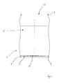
- FIG. 1 a container 2 for the disposable container 1 in a first embodiment without mounted attachment 3 is shown.
- the container 2 has a substantially circular container bottom 4 and a container wall 5 connected thereto.
- the container bottom 4 is curved in its inner region in the direction of the container interior.
- the outer edge 6 of the container bottom 4 in this way forms an annular standing area, on which the disposable container 1 can be set up safely and stably.
- the outer edge 6 has a folded outwardly and in the direction of the container wall 5 fold 7, in which the outer edge 6 of the bottom 4 is received fluid and pressure-tight.
- a container lid 10 is disposed on the container bottom 4 opposite side of the container wall 5.
- the container lid 10 is curved in its inner region as well as the container bottom 4 in the direction of the container interior, so that a peripheral lid edge 11 is formed. This is similar to the container bottom 4 with the upper fold 9 of the container wall 5 by a flange fluid and pressure-tight manner.
- the peripheral lid edge 11 forms a base, on which the container 2 can be turned off and stored as a semi-finished product or for a filling by means of filling lance.
- the shape of the container bottom 4 and the outer edge 6 are adapted to the shape of the container lid 10 and the lid edge 11, so that container bottom 4 and container lid 10 of two successive Stacked container 2 into each other and partly can grip around each other, so that the container 2 as a semi-finished are particularly good stackable, storable and transportable.
- a filling opening 13 is provided centrally.
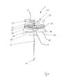
- the attachment 3 for the disposable container 1 is shown separately in a schematic side view in FIG. 3 shown.
- the attachment 3 has a base body 14. This is at the intended arrangement of the article 3 the container 2 facing side corresponding to the shape of the container, for example, circular and has an annular end edge 15 whose inner diameter is slightly larger than the outer diameter of the upper lid edge 11, so that he the container 2 can embrace.
- the annular end edge 15 is seated on a disc-shaped cover portion 16, in the middle of the filling opening 13 is provided.
- hook-like locking elements 17 are provided which project from the lid portion 16 in the direction of the container 2 and, as from FIG. 4 can be seen, engage around the cover rim 11 at a proper arrangement of the article 3 on the container 2.
- a riser 18 is provided, which is either formed directly on the lid portion 16 or sealingly connected thereto.
- the length of the riser 18 is dimensioned such that its open lower riser end 19 terminates in a trough-like depression 20 of the container bottom 4. In this way, it is ensured that color fluid received via the riser 18 in the container 2 can be removed substantially completely and without residue.
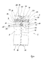
- FIG. 4 shows the disposable container 1 with in FIG. 2 illustrated variant of the container 2 with container lid 10 and filling opening 13.
- the riser 18 is passed through the filling opening 13.
- the seal between riser 18 and container lid 10 via a introduced into the filling opening 13 and the riser 18 fluidly and pressure-tight surrounding plug 23.
- attachment of the attachment 3 takes place on the container 2 via the lid edge 11 and the upper fold 9 encompassing locking elements 17th
- the riser 18 opens into a tube 24. This connects the riser 18 with a spray gun 25. From the container interior via the riser 18 sucked Color fluid is passed through the tube 24 to the spray gun 25.
- the tube 24 is wound in a recess 26 formed on the outside of the attachment 3 for transport and storage purposes and can be unwound for spraying the color fluid.
- two opposing and ring-segment-like handles 27 are formed.
- the facing away from the container 2 end faces 28 of the handle 27 are formed flat and parallel to the outer edge 6 level, so that several disposable containers 1 are stacked one above the other by a disposable container is placed on another disposable container, the outer edge 6 of the upper disposable container, the handles 27th can embrace the lower disposable container, so that a particularly stable state is possible.
- FIG. 4 shows that the spray gun 25 in this inner region 21 can be arranged and durable by means of a clamping device, not shown.
- a CO 2 print cartridge 29 filled with 38g CO 2 as blowing agent is indicated.
- the CO 2 print cartridge 29 is a in the Figures 3 and 4 only schematically indicated pressure control valve 30 connected to the container interior. Via the pressure control valve 30 it is achieved that during a removal of the color fluid in the interior of the container 2 continuously the desired pressure prevails, so that a uniform spray result can be achieved up to a complete emptying of the disposable container 1.
- the spray gun 25 is formed in the form of a plastic injection molded component as a disposable spray gun. It has a non-illustrated in the figures and actuated by a handle shut-off valve. For spraying of recorded in the container 2 color fluid, the container interior is acted upon via the pressure control valve unit 30 with CO 2 as blowing agent from the CO 2 -Printpatrone 29, so that the desired and largely constant internal pressure is ensured for the removal.
- the shut-off valve is opened by actuating the spray gun 25, color fluid contained in the container 2 under overpressure is sprayed out through the riser pipe 18, the hose 24 and the spray gun 25.
Landscapes
- Containers And Packaging Bodies Having A Special Means To Remove Contents (AREA)
Priority Applications (5)
| Application Number | Priority Date | Filing Date | Title |
|---|---|---|---|
| EP09169523A EP2277629A1 (fr) | 2009-07-23 | 2009-09-04 | Fût jetable pour fluide coloré et procédé de fabrication d'un tel fût jetable |
| PCT/EP2010/060262 WO2011009809A1 (fr) | 2009-07-23 | 2010-07-15 | Fûts à usage unique pour fluides colorés et procédé de fabrication d'un tel fût à usage unique |
| EP10730814A EP2456566A1 (fr) | 2009-07-23 | 2010-07-15 | Fûts à usage unique pour fluides colorés et procédé de fabrication d'un tel fût à usage unique |
| US13/386,664 US20120193451A1 (en) | 2009-07-23 | 2010-07-15 | Disposable container for colored fluid and method for producing such a disposal container |
| RU2012100620/05A RU2012100620A (ru) | 2009-07-23 | 2010-07-15 | Одноразовый контейнер для цветной жидкости и способ производства такого контейнера |
Applications Claiming Priority (2)
| Application Number | Priority Date | Filing Date | Title |
|---|---|---|---|
| EP09009567 | 2009-07-23 | ||
| EP09169523A EP2277629A1 (fr) | 2009-07-23 | 2009-09-04 | Fût jetable pour fluide coloré et procédé de fabrication d'un tel fût jetable |
Publications (1)
| Publication Number | Publication Date |
|---|---|
| EP2277629A1 true EP2277629A1 (fr) | 2011-01-26 |
Family
ID=42245952
Family Applications (2)
| Application Number | Title | Priority Date | Filing Date |
|---|---|---|---|
| EP09169523A Withdrawn EP2277629A1 (fr) | 2009-07-23 | 2009-09-04 | Fût jetable pour fluide coloré et procédé de fabrication d'un tel fût jetable |
| EP10730814A Withdrawn EP2456566A1 (fr) | 2009-07-23 | 2010-07-15 | Fûts à usage unique pour fluides colorés et procédé de fabrication d'un tel fût à usage unique |
Family Applications After (1)
| Application Number | Title | Priority Date | Filing Date |
|---|---|---|---|
| EP10730814A Withdrawn EP2456566A1 (fr) | 2009-07-23 | 2010-07-15 | Fûts à usage unique pour fluides colorés et procédé de fabrication d'un tel fût à usage unique |
Country Status (4)
| Country | Link |
|---|---|
| US (1) | US20120193451A1 (fr) |
| EP (2) | EP2277629A1 (fr) |
| RU (1) | RU2012100620A (fr) |
| WO (1) | WO2011009809A1 (fr) |
Families Citing this family (1)
| Publication number | Priority date | Publication date | Assignee | Title |
|---|---|---|---|---|
| DE102014223307B4 (de) * | 2014-11-14 | 2020-07-16 | Gema Switzerland Gmbh | Pulverbehälter zur Versorgung einer Sprühbeschichtungsanlage mit Beschichtungspulver |
Citations (6)
| Publication number | Priority date | Publication date | Assignee | Title |
|---|---|---|---|---|
| GB1196965A (en) * | 1967-09-19 | 1970-07-01 | Nat Can Corp | Attachment for Supplying Gas Pressure to and Dispensing a Product from a Disposable Container |
| AT313780B (de) * | 1970-07-24 | 1974-03-11 | Schmidt Max | Sprühflasche bzw. Sprühdose |
| DE9000880U1 (de) * | 1988-11-14 | 1990-03-29 | Prevor International S.A.R.L., Paris | Autonome, tragbare und sterile Dusche zum Waschen von, insbesondere von chemischen Produkten, angegriffenen Teilen des menschlichen oder tierischen Körpers |
| WO1992019386A1 (fr) * | 1991-05-08 | 1992-11-12 | Zeljko Bodulovic | Applicateur de liquide |
| DE69103126T2 (de) * | 1990-11-09 | 1995-03-23 | Prevor Int | Behälter für sterile, tragbare, selbstständige Dusche und damit ausgerüstete Dusche. |
| US6481642B1 (en) * | 2000-08-28 | 2002-11-19 | Ralph Frank Louis, Jr. | Portable misting apparatus and method for delivering a mist |
-
2009
- 2009-09-04 EP EP09169523A patent/EP2277629A1/fr not_active Withdrawn
-
2010
- 2010-07-15 RU RU2012100620/05A patent/RU2012100620A/ru not_active Application Discontinuation
- 2010-07-15 EP EP10730814A patent/EP2456566A1/fr not_active Withdrawn
- 2010-07-15 US US13/386,664 patent/US20120193451A1/en not_active Abandoned
- 2010-07-15 WO PCT/EP2010/060262 patent/WO2011009809A1/fr not_active Ceased
Patent Citations (6)
| Publication number | Priority date | Publication date | Assignee | Title |
|---|---|---|---|---|
| GB1196965A (en) * | 1967-09-19 | 1970-07-01 | Nat Can Corp | Attachment for Supplying Gas Pressure to and Dispensing a Product from a Disposable Container |
| AT313780B (de) * | 1970-07-24 | 1974-03-11 | Schmidt Max | Sprühflasche bzw. Sprühdose |
| DE9000880U1 (de) * | 1988-11-14 | 1990-03-29 | Prevor International S.A.R.L., Paris | Autonome, tragbare und sterile Dusche zum Waschen von, insbesondere von chemischen Produkten, angegriffenen Teilen des menschlichen oder tierischen Körpers |
| DE69103126T2 (de) * | 1990-11-09 | 1995-03-23 | Prevor Int | Behälter für sterile, tragbare, selbstständige Dusche und damit ausgerüstete Dusche. |
| WO1992019386A1 (fr) * | 1991-05-08 | 1992-11-12 | Zeljko Bodulovic | Applicateur de liquide |
| US6481642B1 (en) * | 2000-08-28 | 2002-11-19 | Ralph Frank Louis, Jr. | Portable misting apparatus and method for delivering a mist |
Also Published As
| Publication number | Publication date |
|---|---|
| RU2012100620A (ru) | 2013-08-27 |
| US20120193451A1 (en) | 2012-08-02 |
| EP2456566A1 (fr) | 2012-05-30 |
| WO2011009809A1 (fr) | 2011-01-27 |
Similar Documents
| Publication | Publication Date | Title |
|---|---|---|
| DE69904235T2 (de) | Behälter zum aufbewahren und abgeben von getränke, insbesondere von bier | |
| EP2490819B1 (fr) | Réservoir de peinture notamment destiné à des pistolets à peinture | |
| DE60209540T2 (de) | Zapfventil | |
| DE69404386T2 (de) | Sprühkopf für pastose Produkte und damit ausgestattete Abgabevorrichtung | |
| EP2022751B1 (fr) | dispositif de soutirage | |
| DE19513886A1 (de) | Wiederbefüllbare Aerosoldose | |
| DE1303782B (fr) | ||
| DE3008837C2 (fr) | ||
| DE102004037448B4 (de) | Pastenausgabevorrichtung mit Mitttelsäule | |
| DE2903599A1 (de) | Geraet zum abgeben eines mediums, z.b. einer fluessigkeit | |
| WO1994006703A1 (fr) | Recipient pour le stockage et le transport de milieux coulants, principalement de liquides | |
| EP2328816B1 (fr) | Récipient doseur tubulaire | |
| EP2277629A1 (fr) | Fût jetable pour fluide coloré et procédé de fabrication d'un tel fût jetable | |
| EP2414103B1 (fr) | Réservoir jetable, son utilisation et un procédé de le mettre sous pression | |
| DE9107504U1 (de) | Nachfüllbares Verpackungssystem für flüssige oder pastöse Produkte | |
| EP3684706A1 (fr) | Revêtement intérieur | |
| DE4327442A1 (de) | Faß, das besonders zum Versenden von Chemikalien oder Abfällen geeignet ist | |
| DE8800584U1 (de) | Vorrichtung zum Versprühen von Stoffen mit einem Einsatzbehälter | |
| EP3371068B1 (fr) | Boîte de boisson à usage unique en acier et méthode pour sa production | |
| DE2127259A1 (de) | Behaelter vom wegwerftyp, versehen mit einer zapfvorrichtung | |
| DE4431181C1 (de) | Behälter für Flüssigkeiten | |
| DE8214181U1 (de) | Ziehharmonikafoermiger Weinbehaelter | |
| DE102007057209A1 (de) | Vorrichtung zum Befüllen eines Behälters mit einem Fluid | |
| DE102008056813A1 (de) | Behälter und Verfahren zum Füllen eines Behälters | |
| DE10326474B4 (de) | Druckbehälter |
Legal Events
| Date | Code | Title | Description |
|---|---|---|---|
| PUAI | Public reference made under article 153(3) epc to a published international application that has entered the european phase |
Free format text: ORIGINAL CODE: 0009012 |
|
| AK | Designated contracting states |
Kind code of ref document: A1 Designated state(s): AT BE BG CH CY CZ DE DK EE ES FI FR GB GR HR HU IE IS IT LI LT LU LV MC MK MT NL NO PL PT RO SE SI SK SM TR |
|
| AX | Request for extension of the european patent |
Extension state: AL BA RS |
|
| STAA | Information on the status of an ep patent application or granted ep patent |
Free format text: STATUS: THE APPLICATION IS DEEMED TO BE WITHDRAWN |
|
| 18D | Application deemed to be withdrawn |
Effective date: 20110727 |