EP2277792B1 - Verschluss - Google Patents
Verschluss Download PDFInfo
- Publication number
- EP2277792B1 EP2277792B1 EP20100007702 EP10007702A EP2277792B1 EP 2277792 B1 EP2277792 B1 EP 2277792B1 EP 20100007702 EP20100007702 EP 20100007702 EP 10007702 A EP10007702 A EP 10007702A EP 2277792 B1 EP2277792 B1 EP 2277792B1
- Authority
- EP
- European Patent Office
- Prior art keywords
- closure
- container
- flap
- lid
- cap
- Prior art date
- Legal status (The legal status is an assumption and is not a legal conclusion. Google has not performed a legal analysis and makes no representation as to the accuracy of the status listed.)
- Not-in-force
Links
- 206010053648 Vascular occlusion Diseases 0.000 description 10
- 238000004806 packaging method and process Methods 0.000 description 2
- 235000013361 beverage Nutrition 0.000 description 1
- 238000011161 development Methods 0.000 description 1
- 230000018109 developmental process Effects 0.000 description 1
- 238000004519 manufacturing process Methods 0.000 description 1
- 238000000034 method Methods 0.000 description 1
- 238000003801 milling Methods 0.000 description 1
- 230000035515 penetration Effects 0.000 description 1
- 239000000047 product Substances 0.000 description 1
- 239000006228 supernatant Substances 0.000 description 1
- 210000002105 tongue Anatomy 0.000 description 1
Images





Classifications
-
- B—PERFORMING OPERATIONS; TRANSPORTING
- B65—CONVEYING; PACKING; STORING; HANDLING THIN OR FILAMENTARY MATERIAL
- B65D—CONTAINERS FOR STORAGE OR TRANSPORT OF ARTICLES OR MATERIALS, e.g. BAGS, BARRELS, BOTTLES, BOXES, CANS, CARTONS, CRATES, DRUMS, JARS, TANKS, HOPPERS, FORWARDING CONTAINERS; ACCESSORIES, CLOSURES, OR FITTINGS THEREFOR; PACKAGING ELEMENTS; PACKAGES
- B65D43/00—Lids or covers for rigid or semi-rigid containers
- B65D43/14—Non-removable lids or covers
- B65D43/22—Devices for holding in closed position, e.g. clips
-
- E—FIXED CONSTRUCTIONS
- E05—LOCKS; KEYS; WINDOW OR DOOR FITTINGS; SAFES
- E05B—LOCKS; ACCESSORIES THEREFOR; HANDCUFFS
- E05B65/00—Locks or fastenings for special use
- E05B65/08—Locks or fastenings for special use for sliding wings
- E05B65/0835—Locks or fastenings for special use for sliding wings the bolts pivoting about an axis parallel to the wings
-
- E—FIXED CONSTRUCTIONS
- E05—LOCKS; KEYS; WINDOW OR DOOR FITTINGS; SAFES
- E05B—LOCKS; ACCESSORIES THEREFOR; HANDCUFFS
- E05B65/00—Locks or fastenings for special use
- E05B65/52—Other locks for chests, boxes, trunks, baskets, travelling bags, or the like
- E05B65/5207—Other locks for chests, boxes, trunks, baskets, travelling bags, or the like characterised by bolt movement
- E05B65/5246—Other locks for chests, boxes, trunks, baskets, travelling bags, or the like characterised by bolt movement rotating
- E05B65/5269—Other locks for chests, boxes, trunks, baskets, travelling bags, or the like characterised by bolt movement rotating about an axis parallel to the surface on which the lock is mounted
- E05B65/5276—Other locks for chests, boxes, trunks, baskets, travelling bags, or the like characterised by bolt movement rotating about an axis parallel to the surface on which the lock is mounted parallel to the wing edge
-
- E—FIXED CONSTRUCTIONS
- E05—LOCKS; KEYS; WINDOW OR DOOR FITTINGS; SAFES
- E05C—BOLTS OR FASTENING DEVICES FOR WINGS, SPECIALLY FOR DOORS OR WINDOWS
- E05C3/00—Fastening devices with bolts moving pivotally or rotatively
- E05C3/02—Fastening devices with bolts moving pivotally or rotatively without latching action
- E05C3/04—Fastening devices with bolts moving pivotally or rotatively without latching action with operating handle or equivalent member rigid with the bolt
- E05C3/047—Fastening devices with bolts moving pivotally or rotatively without latching action with operating handle or equivalent member rigid with the bolt rotating about an axis parallel to the surface on which the fastener is mounted
- E05C3/048—Fastening devices with bolts moving pivotally or rotatively without latching action with operating handle or equivalent member rigid with the bolt rotating about an axis parallel to the surface on which the fastener is mounted parallel to the wing edge
Definitions
- the invention relates to a closure for box-shaped container having a top portion formed by a cap, in which a flap is pivotally mounted, wherein on the flap a spring held in the cap rests.
- a snap closure for windows and doors is for example from the WO 99/29991 A1 known.
- Closures of the type mentioned are known in many ways. They serve to secure boxes, cases, caskets and the like. In these, the upper part forming cap is struck on a box or case top. Corresponding thereto, a closure lower part is struck on the lower part of the box, which is overlapped in the closed state of the closure of the pivotable cap.
- opening the shutter moves the flap under the influence of the spring in a predetermined end position.
- the lid of the box can then be opened. After closing the lid of the closure against the spring force is moved back to its original position in which it engages over the lower part of the closure and secures the lid of the container against opening.
- closures meet the requirements met on them.
- the closures require in each case a lower part, which is struck on the lower part of the container, as far as the upper closure part is struck on the lid or, in the opposite case, in which the upper part of the closure is hinged to the box, a lower part, which on the lid the container is attached.
- a very precise striking of the upper and lower parts of the closures is required to accomplish a functionally reliable correspondence of the two parts together.
- this type of closures has the disadvantage that they can not be used in sliding lid containers. These containers are particularly popular as packaging for wine-based beverages. In them, a lid is guided in the box forming the lower part of the packaging in grooves. To open the lid is simply moved along the grooves.
- the sliding covers are usually not secured against self-opening. However, during transport, this can lead to the sliding cover automatically slipping out of its closed position and the product located in the container falling out. Since containers sealed with sliding lids often contain high quality drinks containing wine, this causes considerable damage. For this reason, when filling the boxes, the sliding covers are often secured with small nails against self-opening, which, however, on the one hand consuming, on the other hand is awkward to open for the recipient.
- the invention aims to remedy this situation.
- the invention has for its object to provide a closure for box-shaped container, which is used on the one hand in containers with sliding lids and can be dispensed with in the tailor-made striking the correspondence between the upper and lower part of the closure.
- this object is achieved in that the closure is formed subdivided and on the flap, a projection is provided which engages behind a portion of the container and the flap is pivotable through at least 180 °.
- a closure for box-shaped container which allows a reliable closure of box-shaped containers without the use of a lower part.
- the closure according to the invention allows a flush closure with the circumference of the respective container, so that no disadvantageous for the transport supernatant caused by the closure according to the invention.
- the closure chosen as an exemplary embodiment has an upper part formed by a cap 1, in which a flap 2 is pivotably articulated. On the flap 2 is a held in the cap 1 spring 4 is applied.
- the closure is attachable to container 6.
- the cap 1 is provided on its side facing the container 6 with impact tips 11, by means of which the cap 1 can be attached to the container.
- the non-enveloped in the container areas of the impact tips 11 form the two lateral boundaries of the cap 1. It has a viewing surface 13 which is angled at its longitudinal sides perpendicular to a bottom 15 and a ceiling 16. On the viewing surface 13 opposite a support side 14 is provided.
- the flap 2 is formed in the form of a plate 21 encircling, retracted edges 22.
- the height of the edges 22 is substantially equal to the thickness of the cap 1.
- the flap 2 is provided with a recess 23 which is filled by the cap 1 when the closure is closed.
- a projection 24 is provided on the local edge 22.
- the spring 4 is angled substantially U-shaped. With its free leg 41 it lies against the inside of the viewing surface 13 of the cap 1. With its other leg 42, it is supported in the region of the support side 14 of the cap 1. The spring 4 is captively fastened by means of tongues in the cap 1.
- the closure according to the invention is subdivided. In this way, the simultaneous striking of a second part of the closure, as is known from the prior art, avoided. As a result, the striking process is considerably simplified. At the same time, however, a reliable closeability of the respective container is ensured by means of the closure according to the invention.
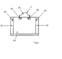
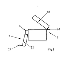
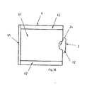
- This is made possible by the projection 24, as in particular the Figures 3 . 6 . 8th . 10 and 12 can be seen. From these figures it can be seen that the projection 24 engages behind a part of the respective container 6. So is in the embodiment of the FIGS. 1 to 4 the closure is arranged on the sliding cover 61.
- the sliding cover 61 is guided in the side walls 62 of the container, in grooves 63 which are milled horizontally in the side walls 62.
- the sliding cover 61 is also provided for ease of opening at its end facing away from the closure with a handle rail 64.
- the container 6 is closed by the frontal walls 65.
- the flap 2 is folded after closing the lid 6 in a simple manner against the action of the spring 4.
- the flap 2 partially overlaps the end wall 65, wherein the plate 21 partially rests on the end wall 65 and the right angles to the wall 65 aligned edges 22 are arranged in recesses 66 in the wall 65.
- the front wall 65 as from the FIGS. 1 and 5 becomes clear.
- the closure according to the invention protrudes only minimally over the container, so that obstruction during transport through the closure or during handling of the closure is not to be feared. It should also be considered that the penetration of the recesses 66 in the container 6 is not a significant overhead, since the required milling process anyway for the creation of the grooves 63 in the container 6 as a guide of the sliding cover 61 is required.
- the closure according to the invention makes it possible to close containers with sliding covers without protruding beyond the dimensions of the container. Due to the recessed arrangement of sliding lids in the respective containers, the closure according to the invention with the viewing surface 13 of the cap 1 and the plate 21 of the flap 2 at most flush with the upper ends of the side walls 62 and the front-side wall 65 and the handle rail 64 from as this particular FIG. 3 can be seen. In addition, only the edge 22 of the flap 2, which is provided with the projection 24, protrudes beyond the end wall 65. As a result, the transportability of the container is ensured unchanged when using the closure according to the invention. Even in the applications in which containers are provided with hinged lids, only on the side on which engages the projection behind the respective lid, a minimal projection caused. At the same time, however, a reliable closure is possible, omitting another component.
- the closure also offers the advantage of an automatic abutment to the container. This is ensured by the fact that the closure parts attached to a Leitband the stopper machine can be fed and can be struck automatically. A manual feeding of the closure parts is thereby avoided, whereby the costs are reduced.
- the arrangement of the closure parts on a guide band has the advantage that the tape with the closure parts can be wound up, whereby the transport to the stopper machine is simplified.
Landscapes
- Engineering & Computer Science (AREA)
- Mechanical Engineering (AREA)
- Closures For Containers (AREA)
Description
- Die Erfindung betrifft einen Verschluss für kastenförmige Behälter, der ein von einer Kappe gebildetes Oberteil aufweist, in der eine Klappe schwenkbar angelenkt ist, wobei an der Klappe eine in der Kappe gehaltene Feder anliegt.
- Ein Schnappverschluss für Fenster und Türen ist beispielsweise aus der
WO 99/29991 A1 - Die bekannten Verschlüsse erfüllen die an sie erfüllten Anforderungen. Die Verschlüsse benötigen jedoch jeweils ein Unterteil, welches an dem Unterteil des Behälters angeschlagen ist, soweit der Verschlussoberteil an dem Deckel angeschlagen ist oder, im umgekehrten Fall, in dem das Oberteil des Verschlusses an dem Kasten angeschlagen ist, ein Unterteil, welches an dem Deckel des Behälters befestigt ist. Hierdurch ist ein sehr präzises Anschlagen der Ober- und Unterteile der Verschlüsse erforderlich, um eine funktionssichere Korrespondenz der beiden Teile miteinander zu bewerkstelligen. Zudem weist diese Art der Verschlüsse den Nachteil auf, dass sie nicht bei Schiebedeckel-Behältern einsetzbar sind. Diese Behälter sind insbesondere als Verpackungen für weinhaltige Getränke sehr beliebt. Bei ihnen ist ein Deckel in dem den Kasten bildenden Unterteil der Verpackung in Nuten geführt. Zum Öffnen wird der Deckel einfach entlang der Nuten verschoben.
- Die Schiebedeckel sind in der Regel nicht gegen selbständiges Öffnen gesichert. Dies kann jedoch beim Transport dazu führen, dass der Schiebedeckel selbständig aus seiner verschlossenen Position verrutscht und das in dem Behälter befindliche Gut herausfällt. Da die mit Schiebedeckeln verschlossenen Behälter oftmals hochwertige weinhaltige Getränke beinhalten, ist hierdurch ein erheblicher Schaden hervorgerufen. Aus diesem Grund werden beim Befüllen der Kästen die Schiebedeckel oftmals mit kleinen Nägeln gegen selbständiges Öffnen gesichert, was jedoch einerseits aufwendig, andererseits für den Empfänger umständlich zu öffnen ist.
- Hier will die Erfindung Abhilfe schaffen. Der Erfindung liegt die Aufgabe zugrunde, einen Verschluss für kastenförmige Behälter zu schaffen, der einerseits bei Behältern mit Schiebedeckeln einsetzbar ist und bei den auf das passgenaue Anschlagen zur Korrespondenz zwischen Ober- und Unterteil des Verschlusses verzichtet werden kann. Gemäß der Erfindung wird diese Aufgabe dadurch gelöst, dass der Verschluss unterteillos ausgebildet ist und an der Klappe ein Vorsprung vorgesehen ist, der hinter einen Teil des Behälters greift und die Klappe um mindestens 180° schwenkbar ist.
- Mit der Erfindung ist ein Verschluss für kastenförmige Behälter geschaffen, der ohne Verwendung eines Unterteils ein zuverlässiges Verschließen von kastenförmigen Behältern ermöglicht. Durch den Verzicht auf das Unterteil ist auch das Verschließen von Behältern mit Schiebedeckel möglich, da kein zusätzliches Bauteil an dem Behälter-Unterteil anzuordnen ist. Gleichzeitig ermöglicht der erfindungsgemäße Verschluss einen bündigen Abschluss mit dem Umfang des jeweiligen Behälters, so dass kein für den Transport ungünstiger Überstand durch den erfindungsgemäßen Verschluss hervorgerufen ist.
- Andere Weiterbildungen und Ausgestaltungen der Erfindung sind in den übrigen Unteransprüchen angegeben. Ein Ausführungsbeispiel der Erfindung ist in der Zeichnung dargestellt und wird nachfolgend im Einzelnen beschrieben. Es zeigen:
- Fig. 1
- die Draufsicht auf einen Schiebedeckel-Behälter mit Verschluss;
- Fig. 2
- die Draufsicht auf den in
Figur 1 dargestellten Behälter mit teilweise geöffneten Schiebedeckel und geöffnetem Verschluss; - Fig. 3
- die stirnseitige Ansicht des in
Figur 1 dargestellten Verschlusses; - Fig. 4
- die stirnseitige Ansicht des in
Figur 2 dargestellten Verschlusses; - Fig. 5
- den Schnitt entlang der Längsmittellinie durch den in
Figur 1 dargestellten Behälter; - Fig. 6
- die Draufsicht auf einen Behälter mit schwenkbarem Deckel und erfindungsgemäßen Verschluss;
- Fig. 7
- die Draufsicht auf den in
Figur 6 dargestellten Behälter mit geöffne- ten Verschluss; - Fig. 8
- die Seitenansicht des in
Figur 6 dargestellten Verschlusses; - Fig. 9
- die Seitenansicht des in
Figur 7 dargestellten Verschlusses mit teilweise geöffneten Deckel; - Fig. 10
- die Draufsicht auf einen Schiebedeckel-Behälter mit an der Stirnseite angeschlagenem Verschluss;
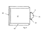
- Fig. 11
- den in
Figur 10 dargestellten Behälter mit teilweise geöffneten Schie- bedeckel und geöffneten Verschluss; - Fig. 12
- die Draufsicht auf einen Schiebedeckel-Behälter mit zwei erfin- dungsgemäßen Verschlüssen.
- Der als Ausführungsbeispiel gewählte Verschluss weist ein von einer Kappe 1 gebildetes Oberteil auf, in der eine Klappe 2 schwenkbar angelenkt ist. An der Klappe 2 liegt eine in der Kappe 1 gehaltene Feder 4 an. Der Verschluss ist an Behälter 6 anschlagbar.
- Die Kappe 1 ist auf ihrer den Behälter 6 zugewandten Seite mit Einschlagspitzen 11 versehen, mit deren Hilfe die Kappe 1 an dem Behälter befestigt werden kann. Die nicht in den Behälter eingeschlagenen Bereiche der Einschlagspitzen 11 bilden die beiden seitlichen Begrenzungen der Kappe 1. Sie weist eine Ansichtsfläche 13 auf, die an ihren Längsseiten rechtwinkelig zu einem Boden 15 sowie einer Decke 16 abgewinkelt ist. Auf der der Ansichtsfläche 13 gegenüberliegend ist eine Auflageseite 14 vorgesehen.
- Die Klappe 2 ist in Form einer Platte 21 ringsumlaufenden, eingezogenen Rändern 22 ausgebildet. Die Höhe der Ränder 22 ist im Wesentlichen gleich der Dicke der Kappe 1. Die Klappe 2 ist mit einer Aussparung 23 versehen, die bei geschlossenem Verschluss von der Kappe 1 ausgefüllt ist. Auf der der Kappe 1 abgewandten Seite der Klappe 2 ist an dem dortigen Rand 22 ein Vorsprung 24 vorgesehen.
- Die Feder 4 ist im Wesentlichen U-förmig abgewinkelt. Mit ihrem freien Schenkel 41 liegt sie an der Innenseite der Ansichtsfläche 13 der Kappe 1 an. Mit ihrem anderen Schenkel 42 ist sie im Bereich der Auflageseite 14 der Kappe 1 abgestützt. Die Feder 4 ist mit Hilfe von Zungen in der Kappe 1 unverlierbar befestigt.
- Der erfindungsgemäße Verschluss ist unterteillos ausgebildet. Auf diese Weise ist auf das gleichzeitige Anschlagen eines zweiten Teils des Verschlusses, wie dies aus dem Stand der Technik bekannt ist, vermieden. In Folge dessen ist der Anschlagvorgang wesentlich vereinfacht. Gleichzeitig ist dennoch eine zuverlässige Verschließbarkeit des jeweiligen Behälters mit Hilfe des erfindungsgemäßen Verschlusses gewährleistet. Dies ist durch den Vorsprung 24 ermöglicht, wie dies insbesondere den
Figuren 3 ,6 ,8 ,10 und12 zu entnehmen ist. Aus diesen Figuren ist ersichtlich, dass der Vorsprung 24 hinter einen Teil des jeweiligen Behälters 6 greift. So ist im Ausführungsbeispiel nach denFiguren 1 bis 4 der Verschluss auf dem Schiebedeckel 61 angeordnet. Der Schiebedeckel 61 ist in den Seitenwänden 62 des Behälters geführt, und zwar in Nuten 63, die horizontal in die Seitenwände 62 eingefräst sind. Der Schiebedeckel 61 ist zudem zum leichteren Öffnen an seinem dem Verschluss abgewandten Ende mit einer Griffschiene 64 versehen. Im Übrigen ist der Behälter 6 über die stirnseitigen Wände 65 verschlossen. - Zum Verschließen des in den
Figuren 1 bis 4 dargestellten Schiebedeckel-Behälters wird die Klappe 2 nach Schließen des Deckels 6 in einfacher Weise gegen die Wirkung der Feder 4 umgeklappt. Die Klappe 2 übergreift dabei teilweise die stirnseitige Wand 65, wobei die Platte 21 bereichsweise auf der stirnseitigen Wand 65 aufliegt und die rechtwinkelig zur Wand 65 ausgerichteten Ränder 22 in Aussparungen 66 in der Wand 65 angeordnet sind. In der stirnseitigen Ansicht, wie sie inFigur 3 dargestellt ist, wird deutlich, dass durch diese Ausbildung ein bündiger Abschluss des Verschlusses mit der Oberseite des Behälters 6 möglich ist. Das Gleiche ergibt sich an der stirnseitigen Wand 65, wie aus denFiguren 1 und5 deutlich wird. Auch auf dieser Seite des Behälters steht der erfindungsgemäße Verschluss nur minimal über den Behälter hervor, so dass eine Behinderung beim Transport durch den Verschluss oder bei der Handhabung des Verschlusses nicht zu befürchten ist. Dabei gilt es auch zu berücksichtigen, dass das Eindringen der Aussparungen 66 in den Behälter 6 keinen wesentlichen Mehraufwand darstellt, da der hierzu erforderliche Fräsvorgang ohnehin für die Erstellung der Nuten 63 in dem Behälter 6 als Führung des Schiebedeckels 61 erforderlich ist. - Auch bei der in den Ausführungsbeispielen nach den
Figuren 6 bis 9 dargestellten Art des Anschlagens an einen kastenförmigen Behälter 6, der über Scharniere 67 mit einem schwenkbaren Deckel 68 versehen ist, ist durch den erfindungsgemäßen Verschluss ein bündiger Abschluss hervorgerufen. Gleichzeitig ist ein zuverlässiges Verschließen des Behälters 6 auch ohne Verwendung eines Unterteils möglich, da die Klappe 2, wie aus denFiguren 6 und8 ersichtlich, bereichsweise den Deckel 68 übergreift und der Vorsprung 24 derart über diesen schwenkt, dass ein Öffnen des Deckels ohne Öffnen des Verschlusses wirksam verhindert ist. - Vergleichbar ist im Ausführungsbeispiel in
Figur 10 der erfindungsgemäße Verschluss an einer Stirnseite eines Schiebedeckel-Verschlusses angeschlagen. Auch hier übergreift in geschlossenem Zustand des Verschlusses (Figur 10 ) die Klappe 2 bereichsweise den Schiebedeckel 61, wobei der Vorsprung 24 über den Schiebedeckel 61 ragt. Ebenso gilt dies für das Ausführungsbeispiel nachFigur 12 , in dem an beiden stirnseitigen Wänden 65 ein erfindungsgemäßer Verschluss angeschlagen ist und jeweils der Vorsprung 24 über den Schiebedeckel 61 ragt. - Der erfindungsgemäße Verschluss ermöglicht das Verschließen von Behältern mit Schiebedeckel, ohne über die Abmessungen des Behälters hinauszuragen. Aufgrund der vertieften Anordnung von Schiebedeckeln in den jeweiligen Behältern, schließt der erfindungsgemäße Verschluss mit der Ansichtsfläche 13 der Kappe 1 bzw. der Platte 21 der Klappe 2 höchstens bündig mit den oberen Enden der Seitenwände 62 bzw. der stirnseitigen Wand 65 und der Griffschiene 64 ab, wie dies insbesondere
Figur 3 zu entnehmen ist. Zudem ragt lediglich der Rand 22 der Klappe 2, der mit dem Vorsprung 24 versehen ist, über die stirnseitige Wand 65 hinaus. In Folge dessen ist die Transportfähigkeit des Behälters bei Verwendung des erfindungsgemäßen Verschlusses unverändert gewährleistet. Auch bei den Anwendungsfällen, bei denen Behälter mit schwenkbaren Deckeln versehen sind, ist lediglich auf der Seite, auf der der Vorsprung hinter den jeweiligen Deckel greift, ein minimaler Überstand hervorgerufen. Gleichzeitig ist jedoch ein zuverlässiger Verschluss unter Weglassen eines weiteren Bauteils ermöglicht. - Fertigungstechnisch ist dabei insbesondere bemerkenswert, dass das Anschlagen des erfindungsgemäßen Verschlusses auf den gleichen Anschlagmaschinen erfolgen kann, auf denen bisher Verschlüsse unter Verwendung eines Unterteils angeschlagen wurden. Der Verschluss bietet dabei zudem den Vorteil einer automatischen Anschlagbarkeit an die Behälter. Dies ist dadurch gewährleistet, dass die Verschlussteile an einem Leitband befestigt der Anschlagmaschine zugeführt werden können und automatisch angeschlagen werden können. Ein händisches Zuführen der Verschlussteile ist dadurch vermieden, wodurch die Kosten reduziert sind. Außerdem bietet die Anordnung der Verschlussteile an einem Leitband den Vorteil, dass das Band mit den Verschlussteilen aufwickelbar ist, wodurch der Transport zur Anschlagmaschine vereinfacht ist.
Claims (5)
- Verschluss auf einem kastenförmigen Behälter, der ein von einer Kappe (1) gebildetes Oberteil aufweist, in der eine Klappe (2) schwenkbar angelenkt ist, wobei an der Klappe (2) eine in der Kappe (1) gehaltene Feder (4) anliegt, dadurch gekennzeichnet, dass der Verschluss unterteillos ausgebildet ist und an der Klappe (2) ein Vorsprung (24) vorgesehen ist, der hinter einen Teil des Behälters (6) greift und die Klappe (2) um 180° schwenkbar ist.
- Verschluss nach Anspruch 1, dadurch gekennzeichnet, dass der Vorsprung (24) an einem umlaufenden Rand (22) vorgesehen ist.
- Verschluss nach Anspruch 1 oder 2, dadurch gekennzeichnet, dass der Vorsprung (24) einen schwenkbaren Deckel (68) des Behälters teilweise übergreift.
- Verschluss nach einem oder mehreren der vorgenannten Ansprüche, dadurch gekennzeichnet, dass der Verschluss auf einem Schiebedeckel (61) des Behälters angeordnet ist.
- Verschluss nach einem oder mehreren der vorgenannten Ansprüche, dadurch gekennzeichnet, dass der Verschluss an einer stirnseitigen Wand (65) des Behälters angeordnet ist.
Applications Claiming Priority (1)
| Application Number | Priority Date | Filing Date | Title |
|---|---|---|---|
| DE200910034726 DE102009034726A1 (de) | 2009-07-24 | 2009-07-24 | Verschluss |
Publications (2)
| Publication Number | Publication Date |
|---|---|
| EP2277792A1 EP2277792A1 (de) | 2011-01-26 |
| EP2277792B1 true EP2277792B1 (de) | 2013-06-05 |
Family
ID=42989249
Family Applications (1)
| Application Number | Title | Priority Date | Filing Date |
|---|---|---|---|
| EP20100007702 Not-in-force EP2277792B1 (de) | 2009-07-24 | 2010-07-24 | Verschluss |
Country Status (3)
| Country | Link |
|---|---|
| EP (1) | EP2277792B1 (de) |
| DE (1) | DE102009034726A1 (de) |
| ES (1) | ES2425888T3 (de) |
Family Cites Families (8)
| Publication number | Priority date | Publication date | Assignee | Title |
|---|---|---|---|---|
| DE3114774C2 (de) * | 1981-04-11 | 1987-01-02 | Aesculap-Werke Ag Vormals Jetter & Scheerer, 7200 Tuttlingen | Verschluß für einen mittels eines Deckels verschließbaren Sterilisierbehälter |
| DE9403399U1 (de) * | 1994-03-01 | 1994-05-05 | August Vormann GmbH & Co, 58256 Ennepetal | Fenster- oder Türsicherung |
| DE19745116A1 (de) * | 1997-10-11 | 1999-04-15 | Happich Fahrzeug & Ind Teile | Schiebefenstergriff |
| AU1710399A (en) * | 1997-12-11 | 1999-06-28 | Southco, Inc. | Slam latch |
| US20020096517A1 (en) * | 2001-01-19 | 2002-07-25 | Gelardi John A. | Strong hold, weak release pivoting, lifting and sliding recessed fulcrum and lever latch |
| US20020162841A1 (en) * | 2001-05-01 | 2002-11-07 | Amos Shamir | Single action latch |
| DE20304131U1 (de) * | 2003-03-13 | 2003-06-05 | Häfner & Krullmann GmbH, 33818 Leopoldshöhe | Behälter zum Sammeln von Abfall |
| WO2008061026A2 (en) * | 2006-11-12 | 2008-05-22 | Meadwestvaco Corporation | Blister pack container |
-
2009
- 2009-07-24 DE DE200910034726 patent/DE102009034726A1/de not_active Withdrawn
-
2010
- 2010-07-24 EP EP20100007702 patent/EP2277792B1/de not_active Not-in-force
- 2010-07-24 ES ES10007702T patent/ES2425888T3/es active Active
Also Published As
| Publication number | Publication date |
|---|---|
| DE102009034726A1 (de) | 2011-01-27 |
| EP2277792A1 (de) | 2011-01-26 |
| ES2425888T3 (es) | 2013-10-17 |
Similar Documents
| Publication | Publication Date | Title |
|---|---|---|
| AT507950B1 (de) | Deckel eines behälters | |
| DE3329455A1 (de) | Kappenschachtel fuer zigaretten oder dergleichen | |
| DE202009018822U1 (de) | Behälter für Transport und Lagerung von Gütern mit einem Behälterboden und zumindest zwei übereinander klappbaren Seitenwänden | |
| EP0992644B1 (de) | Riegelverschluss zur Montage in einer dünnen Wand | |
| EP2774866A1 (de) | Behälter zur Aufnahme von Kleinteilen | |
| EP2409616B1 (de) | Gutaufnahmebehälter | |
| DE3624345A1 (de) | Cigarettenschachtel | |
| DE102013205103B3 (de) | Eierverpackung | |
| DE202009010123U1 (de) | Verschluss | |
| EP2277792A1 (de) | Verschluss | |
| EP1671889B1 (de) | Vorrichtung zum Verschliessen von Kartondeckeln o.dgl. | |
| EP3962834A1 (de) | Behälter mit selbsttragender abdeckung für auslass | |
| DE4412095C2 (de) | Schnapp-Tray | |
| EP0445372B1 (de) | Kassette zur Aufbewahrung von Gegenständen | |
| DE29511972U1 (de) | Quaderförmiger Kasten aus Kunststoff | |
| DE1928049A1 (de) | Behaeltnis fuer Tabletten od.dgl.,bestehend aus einer Verkaufsschachtel und einer Schutzhuelle | |
| DE202012104804U1 (de) | Schiebeverschluss | |
| EP1484261A1 (de) | Verschliessbarer Deckel für ein Behältnis, insbesondere für eine Dose für Schüttgut | |
| DE4407877A1 (de) | Behältnis mit einer Öffnung und einer Verschlußlasche | |
| DE602005002192T2 (de) | Zusammenlegbare Kiste mit aufklappbaren Seitenwänden und Deckel | |
| EP1579811B1 (de) | Abfallbehälter | |
| EP2202167A1 (de) | Vorrichtung zur Sicherung von Gitterboxklappen | |
| EP0289821B1 (de) | Federscharnier | |
| DE2632410A1 (de) | Verpackung | |
| DE102009005321B3 (de) | Schiebeverschluss |
Legal Events
| Date | Code | Title | Description |
|---|---|---|---|
| PUAI | Public reference made under article 153(3) epc to a published international application that has entered the european phase |
Free format text: ORIGINAL CODE: 0009012 |
|
| AK | Designated contracting states |
Kind code of ref document: A1 Designated state(s): AL AT BE BG CH CY CZ DE DK EE ES FI FR GB GR HR HU IE IS IT LI LT LU LV MC MK MT NL NO PL PT RO SE SI SK SM TR |
|
| AX | Request for extension of the european patent |
Extension state: BA ME RS |
|
| 17P | Request for examination filed |
Effective date: 20110726 |
|
| 17Q | First examination report despatched |
Effective date: 20111128 |
|
| GRAP | Despatch of communication of intention to grant a patent |
Free format text: ORIGINAL CODE: EPIDOSNIGR1 |
|
| GRAS | Grant fee paid |
Free format text: ORIGINAL CODE: EPIDOSNIGR3 |
|
| GRAA | (expected) grant |
Free format text: ORIGINAL CODE: 0009210 |
|
| AK | Designated contracting states |
Kind code of ref document: B1 Designated state(s): AL AT BE BG CH CY CZ DE DK EE ES FI FR GB GR HR HU IE IS IT LI LT LU LV MC MK MT NL NO PL PT RO SE SI SK SM TR |
|
| REG | Reference to a national code |
Ref country code: GB Ref legal event code: FG4D Free format text: NOT ENGLISH |
|
| REG | Reference to a national code |
Ref country code: CH Ref legal event code: EP |
|
| REG | Reference to a national code |
Ref country code: AT Ref legal event code: REF Ref document number: 615541 Country of ref document: AT Kind code of ref document: T Effective date: 20130615 |
|
| REG | Reference to a national code |
Ref country code: IE Ref legal event code: FG4D Free format text: LANGUAGE OF EP DOCUMENT: GERMAN |
|
| REG | Reference to a national code |
Ref country code: DE Ref legal event code: R096 Ref document number: 502010003502 Country of ref document: DE Effective date: 20130801 |
|
| REG | Reference to a national code |
Ref country code: ES Ref legal event code: FG2A Ref document number: 2425888 Country of ref document: ES Kind code of ref document: T3 Effective date: 20131017 |
|
| PG25 | Lapsed in a contracting state [announced via postgrant information from national office to epo] |
Ref country code: NO Free format text: LAPSE BECAUSE OF FAILURE TO SUBMIT A TRANSLATION OF THE DESCRIPTION OR TO PAY THE FEE WITHIN THE PRESCRIBED TIME-LIMIT Effective date: 20130905 Ref country code: FI Free format text: LAPSE BECAUSE OF FAILURE TO SUBMIT A TRANSLATION OF THE DESCRIPTION OR TO PAY THE FEE WITHIN THE PRESCRIBED TIME-LIMIT Effective date: 20130605 Ref country code: SE Free format text: LAPSE BECAUSE OF FAILURE TO SUBMIT A TRANSLATION OF THE DESCRIPTION OR TO PAY THE FEE WITHIN THE PRESCRIBED TIME-LIMIT Effective date: 20130605 Ref country code: SI Free format text: LAPSE BECAUSE OF FAILURE TO SUBMIT A TRANSLATION OF THE DESCRIPTION OR TO PAY THE FEE WITHIN THE PRESCRIBED TIME-LIMIT Effective date: 20130605 Ref country code: LT Free format text: LAPSE BECAUSE OF FAILURE TO SUBMIT A TRANSLATION OF THE DESCRIPTION OR TO PAY THE FEE WITHIN THE PRESCRIBED TIME-LIMIT Effective date: 20130605 Ref country code: GR Free format text: LAPSE BECAUSE OF FAILURE TO SUBMIT A TRANSLATION OF THE DESCRIPTION OR TO PAY THE FEE WITHIN THE PRESCRIBED TIME-LIMIT Effective date: 20130906 |
|
| PGFP | Annual fee paid to national office [announced via postgrant information from national office to epo] |
Ref country code: ES Payment date: 20130722 Year of fee payment: 4 Ref country code: DE Payment date: 20130712 Year of fee payment: 4 |
|
| REG | Reference to a national code |
Ref country code: NL Ref legal event code: VDEP Effective date: 20130605 |
|
| REG | Reference to a national code |
Ref country code: LT Ref legal event code: MG4D |
|
| PG25 | Lapsed in a contracting state [announced via postgrant information from national office to epo] |
Ref country code: BG Free format text: LAPSE BECAUSE OF FAILURE TO SUBMIT A TRANSLATION OF THE DESCRIPTION OR TO PAY THE FEE WITHIN THE PRESCRIBED TIME-LIMIT Effective date: 20130905 Ref country code: HR Free format text: LAPSE BECAUSE OF FAILURE TO SUBMIT A TRANSLATION OF THE DESCRIPTION OR TO PAY THE FEE WITHIN THE PRESCRIBED TIME-LIMIT Effective date: 20130605 |
|
| PGFP | Annual fee paid to national office [announced via postgrant information from national office to epo] |
Ref country code: FR Payment date: 20130719 Year of fee payment: 4 |
|
| PG25 | Lapsed in a contracting state [announced via postgrant information from national office to epo] |
Ref country code: LV Free format text: LAPSE BECAUSE OF FAILURE TO SUBMIT A TRANSLATION OF THE DESCRIPTION OR TO PAY THE FEE WITHIN THE PRESCRIBED TIME-LIMIT Effective date: 20130605 |
|
| BERE | Be: lapsed |
Owner name: SCHMALE GMBH. & CO. KG. Effective date: 20130731 |
|
| PG25 | Lapsed in a contracting state [announced via postgrant information from national office to epo] |
Ref country code: PT Free format text: LAPSE BECAUSE OF FAILURE TO SUBMIT A TRANSLATION OF THE DESCRIPTION OR TO PAY THE FEE WITHIN THE PRESCRIBED TIME-LIMIT Effective date: 20131007 Ref country code: SK Free format text: LAPSE BECAUSE OF FAILURE TO SUBMIT A TRANSLATION OF THE DESCRIPTION OR TO PAY THE FEE WITHIN THE PRESCRIBED TIME-LIMIT Effective date: 20130605 Ref country code: EE Free format text: LAPSE BECAUSE OF FAILURE TO SUBMIT A TRANSLATION OF THE DESCRIPTION OR TO PAY THE FEE WITHIN THE PRESCRIBED TIME-LIMIT Effective date: 20130605 Ref country code: IS Free format text: LAPSE BECAUSE OF FAILURE TO SUBMIT A TRANSLATION OF THE DESCRIPTION OR TO PAY THE FEE WITHIN THE PRESCRIBED TIME-LIMIT Effective date: 20131005 Ref country code: CZ Free format text: LAPSE BECAUSE OF FAILURE TO SUBMIT A TRANSLATION OF THE DESCRIPTION OR TO PAY THE FEE WITHIN THE PRESCRIBED TIME-LIMIT Effective date: 20130605 |
|
| PG25 | Lapsed in a contracting state [announced via postgrant information from national office to epo] |
Ref country code: RO Free format text: LAPSE BECAUSE OF FAILURE TO SUBMIT A TRANSLATION OF THE DESCRIPTION OR TO PAY THE FEE WITHIN THE PRESCRIBED TIME-LIMIT Effective date: 20130605 Ref country code: NL Free format text: LAPSE BECAUSE OF FAILURE TO SUBMIT A TRANSLATION OF THE DESCRIPTION OR TO PAY THE FEE WITHIN THE PRESCRIBED TIME-LIMIT Effective date: 20130605 Ref country code: PL Free format text: LAPSE BECAUSE OF FAILURE TO SUBMIT A TRANSLATION OF THE DESCRIPTION OR TO PAY THE FEE WITHIN THE PRESCRIBED TIME-LIMIT Effective date: 20130605 |
|
| PGFP | Annual fee paid to national office [announced via postgrant information from national office to epo] |
Ref country code: IT Payment date: 20130731 Year of fee payment: 4 |
|
| PG25 | Lapsed in a contracting state [announced via postgrant information from national office to epo] |
Ref country code: MC Free format text: LAPSE BECAUSE OF FAILURE TO SUBMIT A TRANSLATION OF THE DESCRIPTION OR TO PAY THE FEE WITHIN THE PRESCRIBED TIME-LIMIT Effective date: 20130605 |
|
| PLBE | No opposition filed within time limit |
Free format text: ORIGINAL CODE: 0009261 |
|
| STAA | Information on the status of an ep patent application or granted ep patent |
Free format text: STATUS: NO OPPOSITION FILED WITHIN TIME LIMIT |
|
| REG | Reference to a national code |
Ref country code: IE Ref legal event code: MM4A |
|
| PG25 | Lapsed in a contracting state [announced via postgrant information from national office to epo] |
Ref country code: BE Free format text: LAPSE BECAUSE OF NON-PAYMENT OF DUE FEES Effective date: 20130731 Ref country code: DK Free format text: LAPSE BECAUSE OF FAILURE TO SUBMIT A TRANSLATION OF THE DESCRIPTION OR TO PAY THE FEE WITHIN THE PRESCRIBED TIME-LIMIT Effective date: 20130605 |
|
| 26N | No opposition filed |
Effective date: 20140306 |
|
| REG | Reference to a national code |
Ref country code: DE Ref legal event code: R097 Ref document number: 502010003502 Country of ref document: DE Effective date: 20140306 |
|
| PG25 | Lapsed in a contracting state [announced via postgrant information from national office to epo] |
Ref country code: IE Free format text: LAPSE BECAUSE OF NON-PAYMENT OF DUE FEES Effective date: 20130724 |
|
| REG | Reference to a national code |
Ref country code: DE Ref legal event code: R119 Ref document number: 502010003502 Country of ref document: DE |
|
| REG | Reference to a national code |
Ref country code: CH Ref legal event code: PL |
|
| GBPC | Gb: european patent ceased through non-payment of renewal fee |
Effective date: 20140724 |
|
| REG | Reference to a national code |
Ref country code: FR Ref legal event code: ST Effective date: 20150331 |
|
| PG25 | Lapsed in a contracting state [announced via postgrant information from national office to epo] |
Ref country code: IT Free format text: LAPSE BECAUSE OF NON-PAYMENT OF DUE FEES Effective date: 20140724 Ref country code: CH Free format text: LAPSE BECAUSE OF NON-PAYMENT OF DUE FEES Effective date: 20140731 Ref country code: DE Free format text: LAPSE BECAUSE OF NON-PAYMENT OF DUE FEES Effective date: 20150203 Ref country code: LI Free format text: LAPSE BECAUSE OF NON-PAYMENT OF DUE FEES Effective date: 20140731 |
|
| REG | Reference to a national code |
Ref country code: DE Ref legal event code: R119 Ref document number: 502010003502 Country of ref document: DE Effective date: 20150203 |
|
| PG25 | Lapsed in a contracting state [announced via postgrant information from national office to epo] |
Ref country code: FR Free format text: LAPSE BECAUSE OF NON-PAYMENT OF DUE FEES Effective date: 20140731 Ref country code: GB Free format text: LAPSE BECAUSE OF NON-PAYMENT OF DUE FEES Effective date: 20140724 Ref country code: SM Free format text: LAPSE BECAUSE OF FAILURE TO SUBMIT A TRANSLATION OF THE DESCRIPTION OR TO PAY THE FEE WITHIN THE PRESCRIBED TIME-LIMIT Effective date: 20130605 |
|
| PG25 | Lapsed in a contracting state [announced via postgrant information from national office to epo] |
Ref country code: TR Free format text: LAPSE BECAUSE OF FAILURE TO SUBMIT A TRANSLATION OF THE DESCRIPTION OR TO PAY THE FEE WITHIN THE PRESCRIBED TIME-LIMIT Effective date: 20130605 Ref country code: MT Free format text: LAPSE BECAUSE OF FAILURE TO SUBMIT A TRANSLATION OF THE DESCRIPTION OR TO PAY THE FEE WITHIN THE PRESCRIBED TIME-LIMIT Effective date: 20130605 Ref country code: CY Free format text: LAPSE BECAUSE OF FAILURE TO SUBMIT A TRANSLATION OF THE DESCRIPTION OR TO PAY THE FEE WITHIN THE PRESCRIBED TIME-LIMIT Effective date: 20130605 |
|
| PG25 | Lapsed in a contracting state [announced via postgrant information from national office to epo] |
Ref country code: LU Free format text: LAPSE BECAUSE OF NON-PAYMENT OF DUE FEES Effective date: 20130724 Ref country code: MK Free format text: LAPSE BECAUSE OF FAILURE TO SUBMIT A TRANSLATION OF THE DESCRIPTION OR TO PAY THE FEE WITHIN THE PRESCRIBED TIME-LIMIT Effective date: 20130605 Ref country code: HU Free format text: LAPSE BECAUSE OF FAILURE TO SUBMIT A TRANSLATION OF THE DESCRIPTION OR TO PAY THE FEE WITHIN THE PRESCRIBED TIME-LIMIT; INVALID AB INITIO Effective date: 20100724 |
|
| REG | Reference to a national code |
Ref country code: ES Ref legal event code: FD2A Effective date: 20150826 |
|
| PG25 | Lapsed in a contracting state [announced via postgrant information from national office to epo] |
Ref country code: ES Free format text: LAPSE BECAUSE OF NON-PAYMENT OF DUE FEES Effective date: 20140725 |
|
| REG | Reference to a national code |
Ref country code: AT Ref legal event code: MM01 Ref document number: 615541 Country of ref document: AT Kind code of ref document: T Effective date: 20150724 |
|
| PG25 | Lapsed in a contracting state [announced via postgrant information from national office to epo] |
Ref country code: AT Free format text: LAPSE BECAUSE OF NON-PAYMENT OF DUE FEES Effective date: 20150724 |
|
| PG25 | Lapsed in a contracting state [announced via postgrant information from national office to epo] |
Ref country code: AL Free format text: LAPSE BECAUSE OF FAILURE TO SUBMIT A TRANSLATION OF THE DESCRIPTION OR TO PAY THE FEE WITHIN THE PRESCRIBED TIME-LIMIT Effective date: 20130605 |