EP2278072A2 - Dispositif de protection - Google Patents
Dispositif de protection Download PDFInfo
- Publication number
- EP2278072A2 EP2278072A2 EP10007539A EP10007539A EP2278072A2 EP 2278072 A2 EP2278072 A2 EP 2278072A2 EP 10007539 A EP10007539 A EP 10007539A EP 10007539 A EP10007539 A EP 10007539A EP 2278072 A2 EP2278072 A2 EP 2278072A2
- Authority
- EP
- European Patent Office
- Prior art keywords
- wall
- rubber
- base
- base element
- protective
- Prior art date
- Legal status (The legal status is an assumption and is not a legal conclusion. Google has not performed a legal analysis and makes no representation as to the accuracy of the status listed.)
- Withdrawn
Links
- 230000004224 protection Effects 0.000 title claims description 51
- 229920001971 elastomer Polymers 0.000 claims abstract description 85
- 239000002245 particle Substances 0.000 claims abstract description 55
- 239000004567 concrete Substances 0.000 claims abstract description 46
- 239000004033 plastic Substances 0.000 claims abstract description 26
- 229920003023 plastic Polymers 0.000 claims abstract description 26
- 229910000831 Steel Inorganic materials 0.000 claims abstract description 8
- 239000010959 steel Substances 0.000 claims abstract description 8
- 230000001681 protective effect Effects 0.000 claims description 91
- 239000008187 granular material Substances 0.000 claims description 42
- 239000011230 binding agent Substances 0.000 claims description 25
- 239000000203 mixture Substances 0.000 claims description 18
- 239000004568 cement Substances 0.000 claims description 5
- 239000011800 void material Substances 0.000 claims description 5
- 230000008901 benefit Effects 0.000 description 11
- 238000013016 damping Methods 0.000 description 10
- 230000004888 barrier function Effects 0.000 description 7
- 230000009467 reduction Effects 0.000 description 7
- 239000002131 composite material Substances 0.000 description 6
- 239000000463 material Substances 0.000 description 6
- 238000010276 construction Methods 0.000 description 5
- 238000000151 deposition Methods 0.000 description 5
- 230000008021 deposition Effects 0.000 description 5
- 238000009434 installation Methods 0.000 description 5
- 238000004519 manufacturing process Methods 0.000 description 5
- 230000000694 effects Effects 0.000 description 4
- 230000002829 reductive effect Effects 0.000 description 4
- 230000000670 limiting effect Effects 0.000 description 3
- 229910052751 metal Inorganic materials 0.000 description 3
- 239000002184 metal Substances 0.000 description 3
- XLYOFNOQVPJJNP-UHFFFAOYSA-N water Substances O XLYOFNOQVPJJNP-UHFFFAOYSA-N 0.000 description 3
- 229920001875 Ebonite Polymers 0.000 description 2
- 239000000853 adhesive Substances 0.000 description 2
- 230000001070 adhesive effect Effects 0.000 description 2
- 239000000806 elastomer Substances 0.000 description 2
- 230000006872 improvement Effects 0.000 description 2
- 238000000465 moulding Methods 0.000 description 2
- 238000005192 partition Methods 0.000 description 2
- 238000003860 storage Methods 0.000 description 2
- 239000002023 wood Substances 0.000 description 2
- TVEXGJYMHHTVKP-UHFFFAOYSA-N 6-oxabicyclo[3.2.1]oct-3-en-7-one Chemical compound C1C2C(=O)OC1C=CC2 TVEXGJYMHHTVKP-UHFFFAOYSA-N 0.000 description 1
- 238000005299 abrasion Methods 0.000 description 1
- 238000010521 absorption reaction Methods 0.000 description 1
- 230000009471 action Effects 0.000 description 1
- 229910052782 aluminium Inorganic materials 0.000 description 1
- XAGFODPZIPBFFR-UHFFFAOYSA-N aluminium Chemical compound [Al] XAGFODPZIPBFFR-UHFFFAOYSA-N 0.000 description 1
- 230000002238 attenuated effect Effects 0.000 description 1
- 230000005540 biological transmission Effects 0.000 description 1
- 230000008859 change Effects 0.000 description 1
- 238000004140 cleaning Methods 0.000 description 1
- 238000010073 coating (rubber) Methods 0.000 description 1
- 239000011248 coating agent Substances 0.000 description 1
- 238000000576 coating method Methods 0.000 description 1
- 150000001875 compounds Chemical class 0.000 description 1
- 230000001419 dependent effect Effects 0.000 description 1
- 238000009826 distribution Methods 0.000 description 1
- 238000009415 formwork Methods 0.000 description 1
- 238000005246 galvanizing Methods 0.000 description 1
- 239000011810 insulating material Substances 0.000 description 1
- 210000004185 liver Anatomy 0.000 description 1
- 229910001092 metal group alloy Inorganic materials 0.000 description 1
- 239000007769 metal material Substances 0.000 description 1
- 238000000034 method Methods 0.000 description 1
- 239000004745 nonwoven fabric Substances 0.000 description 1
- 230000036961 partial effect Effects 0.000 description 1
- 239000004810 polytetrafluoroethylene Substances 0.000 description 1
- 229920001343 polytetrafluoroethylene Polymers 0.000 description 1
- 230000008092 positive effect Effects 0.000 description 1
- 238000004064 recycling Methods 0.000 description 1
- 230000000284 resting effect Effects 0.000 description 1
- 239000007787 solid Substances 0.000 description 1
- 238000003466 welding Methods 0.000 description 1
Images


Classifications
-
- E—FIXED CONSTRUCTIONS
- E01—CONSTRUCTION OF ROADS, RAILWAYS, OR BRIDGES
- E01F—ADDITIONAL WORK, SUCH AS EQUIPPING ROADS OR THE CONSTRUCTION OF PLATFORMS, HELICOPTER LANDING STAGES, SIGNS, SNOW FENCES, OR THE LIKE
- E01F8/00—Arrangements for absorbing or reflecting air-transmitted noise from road or railway traffic
- E01F8/0005—Arrangements for absorbing or reflecting air-transmitted noise from road or railway traffic used in a wall type arrangement
- E01F8/0029—Arrangements for absorbing or reflecting air-transmitted noise from road or railway traffic used in a wall type arrangement with porous surfaces, e.g. concrete with porous fillers
-
- E—FIXED CONSTRUCTIONS
- E01—CONSTRUCTION OF ROADS, RAILWAYS, OR BRIDGES
- E01B—PERMANENT WAY; PERMANENT-WAY TOOLS; MACHINES FOR MAKING RAILWAYS OF ALL KINDS
- E01B26/00—Tracks or track components not covered by any one of the preceding groups
- E01B26/005—Means for fixing posts, barriers, fences or the like to rails
-
- E—FIXED CONSTRUCTIONS
- E01—CONSTRUCTION OF ROADS, RAILWAYS, OR BRIDGES
- E01F—ADDITIONAL WORK, SUCH AS EQUIPPING ROADS OR THE CONSTRUCTION OF PLATFORMS, HELICOPTER LANDING STAGES, SIGNS, SNOW FENCES, OR THE LIKE
- E01F15/00—Safety arrangements for slowing, redirecting or stopping errant vehicles, e.g. guard posts or bollards; Arrangements for reducing damage to roadside structures due to vehicular impact
- E01F15/02—Continuous barriers extending along roads or between traffic lanes
- E01F15/08—Continuous barriers extending along roads or between traffic lanes essentially made of walls or wall-like elements ; Cable-linked blocks
- E01F15/081—Continuous barriers extending along roads or between traffic lanes essentially made of walls or wall-like elements ; Cable-linked blocks characterised by the use of a specific material
- E01F15/083—Continuous barriers extending along roads or between traffic lanes essentially made of walls or wall-like elements ; Cable-linked blocks characterised by the use of a specific material using concrete
-
- E—FIXED CONSTRUCTIONS
- E01—CONSTRUCTION OF ROADS, RAILWAYS, OR BRIDGES
- E01F—ADDITIONAL WORK, SUCH AS EQUIPPING ROADS OR THE CONSTRUCTION OF PLATFORMS, HELICOPTER LANDING STAGES, SIGNS, SNOW FENCES, OR THE LIKE
- E01F15/00—Safety arrangements for slowing, redirecting or stopping errant vehicles, e.g. guard posts or bollards; Arrangements for reducing damage to roadside structures due to vehicular impact
- E01F15/02—Continuous barriers extending along roads or between traffic lanes
- E01F15/08—Continuous barriers extending along roads or between traffic lanes essentially made of walls or wall-like elements ; Cable-linked blocks
- E01F15/081—Continuous barriers extending along roads or between traffic lanes essentially made of walls or wall-like elements ; Cable-linked blocks characterised by the use of a specific material
- E01F15/086—Continuous barriers extending along roads or between traffic lanes essentially made of walls or wall-like elements ; Cable-linked blocks characterised by the use of a specific material using plastic, rubber or synthetic materials
-
- E—FIXED CONSTRUCTIONS
- E01—CONSTRUCTION OF ROADS, RAILWAYS, OR BRIDGES
- E01F—ADDITIONAL WORK, SUCH AS EQUIPPING ROADS OR THE CONSTRUCTION OF PLATFORMS, HELICOPTER LANDING STAGES, SIGNS, SNOW FENCES, OR THE LIKE
- E01F8/00—Arrangements for absorbing or reflecting air-transmitted noise from road or railway traffic
- E01F8/0005—Arrangements for absorbing or reflecting air-transmitted noise from road or railway traffic used in a wall type arrangement
- E01F8/0023—Details, e.g. foundations
-
- E—FIXED CONSTRUCTIONS
- E01—CONSTRUCTION OF ROADS, RAILWAYS, OR BRIDGES
- E01B—PERMANENT WAY; PERMANENT-WAY TOOLS; MACHINES FOR MAKING RAILWAYS OF ALL KINDS
- E01B19/00—Protection of permanent way against development of dust or against the effect of wind, sun, frost, or corrosion; Means to reduce development of noise
- E01B19/003—Means for reducing the development or propagation of noise
Definitions
- the invention relates to a protective device for arrangement on a traffic route comprising at least one wall element, a wall element for a protective device for installation on a traffic route, comprising at least one surface element, a protective wall system comprising a plurality of protective devices with wall elements, as well as the use of the protective device or the wall element.
- Protective devices in the form of wall elements are constructed on or on traffic routes for different reasons. On the one hand, these protections are used to protect against noise, on the other hand, roadways can be separated from each other, for example in a construction site area, or these protective devices are also used to better protect working areas on traffic routes from passing traffic. Usually, especially in the field of noise barriers, these protective devices are fixedly placed on or next to the traffic route and for this purpose a corresponding foundation is made, on or in which the stands for the noise barriers themselves, normally as I- or H- Beams made of steel are anchored. In addition, there are also mobile protective wall systems, especially for construction areas or on highways to separate the two directions of traffic from each other. These latter guards are usually made of concrete and are either concreted directly on site or connected to the ground.
- guard rails are known from the prior art further, which are constructed laterally next to roads. It should be prevented so that vehicles are thrown in accidents from the road.
- These rails can also be stirred with a so-called underrun protection to prevent slipping under the guardrail itself, for example, by motorcyclists.
- These rails are anchored to the ground, namely, in which the stands on which the guide rails are mounted, are driven into the ground. Thus, these protections are mounted stationarily stable.
- Object of the present invention is to provide an improved protection device for traffic routes.
- the wall element is arranged on at least one base element that is structurally arranged on or adjacent to the traffic route, further by the aforementioned wall element, wherein the surface element at least partly consists of a rubber granulate, as well as by the protective wall system, in which the protective devices or the wall elements are formed according to the invention, and further by the use of the protective device according to the invention and the invention Ben-wall element to reduce the noise level of moving rail vehicles or as a boundary wall on roads.
- the foundation-less design of the protective device wherein it is advantageous that the wall element and the base element are designed separately, so that on the one hand the construction and dismantling of this protection device is simplified, namely an orientation of the protection device itself easier by the base elements can take place, which may in particular also have a lower weight compared to conventional concrete partitions, and only when this alignment is done, the wall elements are arranged on the base element.
- the storage of such protection devices is simplified, namely, since they can be made less bulky and thus have improved stackability, especially if the wall elements are designed flat, ie in comparison to down widening protections, as these from the prior Technics are known to require less space in storage.
- the foundation-less design of the protective device has the advantage that no such foundation must be provided in the ballast bed, and thus the water drainage in the ballast bed can not be affected by the foundation, especially when used in the field of railway lines, especially as a noise protection device. In addition, because of the lack of foundation also the ballast cleaning easier. Due to the at least partial embodiment of the wall element with a rubber granules, that is, the surface element of the wall element, the advantage is achieved that this compared to solid concrete walls may have a lower weight.
- the noise protection behavior That is, the sound absorption or the sound reflection on the granule size are positively influenced and may optionally be given about the rubber granules of this surface element a certain elasticity, so that the impact of a vehicle can be attenuated accordingly or the impact energy can be better degraded.
- the use of rubber granules also contributes to the protection of the environment by, for example, recycling old tires, which are shredded accordingly, thus requiring less landfill volume for these used tires.
- the stability of the composite is further improved.
- this can improve the pull-out strength of this connecting device part from the protective device, whereby corresponding advantages with regard to a collision of a vehicle are obtained.
- the connecting strap is made of steel, so that in particular with regard to the use of concrete for the base element, an improved adhesion of the connecting strap is achieved in the concrete.
- a protective device is provided via the steel tab, which can be exposed to higher loads.
- a part of the base element forms a vertical pivot axis for the connecting device, whereby the advantage is achieved that by the pivotability of individual protection devices to each other in the assembled state, ie in the execution of the protective wall system, even tighter curve radii can be reshaped or Thus, the delimitation of smaller areas is possible because the Verschenkles can reach almost 360 °, so so, for example, rectangular areas can be separated in the course of road construction.
- the pivotability is limited essentially only by the wall thickness of the wall elements.
- the base element can be formed by a flat concrete base.
- the flat concrete base has the advantage that thus a surface pressure is exerted on the underlying ballast of the ballast bed. It has been shown that the underlying gravel grains are subject to less wear, so that therefore the ballast bed must be replaced less frequently in this area. In particular, so that the abrasion and the fine grain content of the ballast bed can be reduced over a longer period.
- the flat concrete base causes the dirt entry from above in the area of the ballast bed can be reduced, which also the life of the ballast bed can be extended.
- the concrete base has a longitudinal extent which corresponds at least approximately to the longitudinal extent of the wall element, whereby the manipulation of the protective device can be simplified. It is thus an embodiment possible, after which extend the wall elements in each case over half of two adjacent base elements in the longitudinal direction, whereby the overall composite can be improved.
- the base element at least one anchor plate for fixing a upright element for receiving the wall element is arranged, in particular this anchor plate is molded or concreted into the base element, on the one hand to simplify the installation of the protection device, that is the entire protective wall system, on the other again to improve the stability of the protective device, namely by the power transmission can be better introduced into the base element.
- this anchor plate is molded or concreted into the base element, on the one hand to simplify the installation of the protection device, that is the entire protective wall system, on the other again to improve the stability of the protective device, namely by the power transmission can be better introduced into the base element.
- the anchor plate is arranged at least approximately in the middle, relative to the width of the base element.
- this anchor plate is arranged in one of the two longitudinal side regions of the base elements in order to be able to arrange the protective device closer to the traffic route, that is to say in particular the wall element of the protective device closer to the noise source.
- the base element has at least one connecting device with which this can be connected to a threshold or to a rail of a track. It can thus also a predeterminable distance to the source of noise generation in the region of the rails during the passage of a train and thus an at least approximately constant noise protection behavior of the protective device can be achieved by namely the lateral distance is kept substantially constant, so that this protection device optionally with a lower height of the wall elements can be performed.
- the protective device better withstand the mechanical loads occurring during the passage of a train.
- connection device For a better connection of this connection device with the base element or for easier mounting, it is possible for the base element along at least one longitudinal extent has a gradation and / or recess, in which engages the connecting device, so that additional fasteners, such as screws, etc., optionally can be omitted, and thus the assembly is easier.
- this connecting device has a stirrup element or a bow-shaped end region, that or the base element is arranged encompassing on its underside, whereby a better connection of this connecting device is achieved with the base element.
- At least the walls of the wall element may consist of a rubber particle / concrete or Kunststoffparrtikkel / plastic particles / plastic binder mixture. It is thus an easier manufacturability of this wall element with appropriate acoustic effect or noise reduction achievable by depending on the requirements of the proportion of rubber particles is selected in this mixture, which is also advantageous that this rubber particles / concrete or rubber particles / plastic particles / plastic binder mixture carried self-supporting can be so that no additional measures for the arrangement of rubber granulate in the wall element are required.
- the proportion of rubber particles in the rubber particles / concrete or rubber particles plastic particles / plastic binder mixture is selected from a range with a lower limit of 10 vol .-% and an upper limit of 70 vol .-% or
- rubber particles are used which have an average grain size selected from a range with a lower limit of 0.4 mm and an upper limit of 4 mm. It was thus possible to improve the noise protection behavior of the protective device according to the invention and thus also to impart a certain elasticity to the wall element, even if it is made of concrete.
- the noise reduction is reduced, although by increasing the proportion of rubber particles in the rubber particles / concrete or rubber particles / plastic particles / plastic binder mixture
- the noise reduction effect can be improved, but to burden this improvement the strength of the protective device, that is, the wall element is, so that such designs can be used with higher proportion of rubber particles in the mixture only for those purposes in which the mechanical load of the protection device is lower.
- the proportion of rubber particles in the rubber particles / concrete or rubber particles / plastic particles / plastic binder mixture to be selected from a range with a lower limit of 20% by volume and an upper limit of 65% by volume. or from a range with a lower limit of 25 vol.% and an upper limit of 55 vol.%.
- the rubber particles have a mean grain size selected from a range having a lower limit of 1 mm and an upper limit of 3.5 mm and a range having a lower limit of 1.5 mm, respectively and an upper limit of 3 mm.
- the wall element is filled with a rubber granulate or at least partially made of it, so that it is better possible, the protection device easier to set to a desired degree of noise reduction.
- this system is more flexible than different wall thicknesses can be used for the wall element, wherein the two outer cover layers are made consistently and only the layer thickness of the rubber granules is changed in the direction of the width of the wall element.
- the rubber granules have a particle size between 0.5 mm and 4 mm, so that therefore different grain sizes are available and thus different frequency ranges can be operated in the course of noise reduction.
- the filling behavior of the wall element with rubber granulate can be positively influenced by the use of different grain sizes.
- cavities in the wall element between the individual rubber granulate grains can be produced which act positively in terms of noise reduction.
- the grain size of the rubber granules may also be selected from a range with a lower limit of 0.7 mm and an upper limit of 2 mm.
- the rubber granulate is bound with a binder, so that in turn a self-supporting wall element is obtained and thus may be dispensed with lateral supporting wall element parts.
- the noise level can be arranged on at least one surface of the rubber granule filling an acoustic fleece, in particular glued.
- the self-supporting design of the rubber granulate binder mixture proves to be an advantage, since the acoustic fleece does not have to fulfill any supporting function.
- the rubber granulate is filled in or consists of particles connected to one another in such a way that cavities are formed between the individual particles.
- the void fraction is between 5% by volume and 30% by volume, based on the total volume occupied by the rubber granules.
- the void fraction prefferably be between 10% by volume and 27.5% by volume and between 15% by volume and 25% by volume.
- At least one support element for the wall element can be arranged on a rear side of the wall element facing away from the traffic route in the installed state.
- This embodiment variant is particularly advantageous if the wall element is not arranged centrally on the base element but in the region of a longitudinal edge of the base element.
- this Ausftlhrtungstage proves advantageous when wall elements are used with a higher height, for example, from 3 m.
- the protective devices or the wall elements are connected to one another in an articulated manner so that, as already stated above, it is easier to reproduce tighter curve radii.
- the Fig. 1 and 2 show a first embodiment of a protective device 1 for arrangement on a traffic route, not shown, such as a road or along a track.
- This protective device 1 is part of a protective wall system 2, said protective wall system 2 according to the Fig. 1 and 2 each of three protective devices 1 is constructed, this number is of course not limiting, but depends on the length of the route at which the protective wall system 2 is to be arranged.
- the protective device 1 comprises a base element 3 and a wall element 4.
- the base element 3 is dish-shaped in this case and in the region of an end face 5 of the wall element 4 - viewed in the longitudinal direction of the wall element 4 - arranged.
- the base element 3 has a connecting device 6 or a part of a connecting device 6, which is aligned at least approximately vertically - in the installed position of the base element 3 - and is bolt-shaped in the present case.
- This connecting device 6 may be made in one piece with the base element 3 or there is also the possibility that the connecting device 6 is connected to the base element 3 anderskyrtig, for example, welded or screwed or clamped.
- the base element 3 consists of a metal or a metal alloy, whereby other materials, such as concrete or the like, are possible.
- the wall element 4 has on its front side 5 on a connecting plate 7, which in turn is in particular formed integrally with the wall element 4.
- This connecting plate 7 comprises a recess 8, through which or into which the bolt-shaped part of the connecting device 6 projects into or through. It is thus achieved an articulated connections of the individual protection devices 1 of the protective wall system 2, so that the individual Wall elements 4 in the protective wall system 2 need not be arranged in alignment with each other, but may also be at an angle to each other, as shown in the Fig. 1 and 2 is shown.
- the wall elements 4 are each provided with two of these connecting straps 7, which are arranged in or on the opposite end faces 5 of the wall element 4. It is advantageous if, viewed in the longitudinal direction of the wall element 4, these connection tabs 7 alternately below and above - seen in the installed position of the protection device 1 - are arranged so that the connecting plates 7 as in the Fig. 1 and 2 represented, in the installed state can be arranged one above the other and thus with a bolt-shaped part of the connecting device 6 each adjacent protective devices 1 can be connected together.
- connection tab 7 is also shown in the right part of the protective wall system 2.
- two wall elements 4 of the protective wall system 2 are thus set up via a connecting device 6 and thus also a base element 3.
- the arrangement of the wall elements 4 can take place in such a way that they are arranged distanced to a bottom surface, not shown. Likewise, there is the possibility that these wall elements 4 have a recess or offset 10 in the region of the connecting straps, in which the base element 3 can be arranged at least partially, so that a large part of the lower end surface 11 of the wall element 4 is on the road, that is can be placed resting on the traffic route, so as to give the protective wall system 2 a higher stability. For the same reason there is a possibility that the base element 3 has a greater width or a larger diameter than the width of the wall element 4, so that in the direction of the width extension the base element 3 protrudes beyond the wall element 4.
- 11 recesses 12 are provided on the lower end face, which extend over the entire width of the wall element 4 in the direction of the traffic route, thus better drainage over this Recesses 12, that is to allow the removal of water in an area adjacent to the traffic route. It can be provided as shown in the example, two recesses 12 per wall element 4, this number is not restrictive, but it is quite possible that only one, in particular larger, recess 12 or more, such as three, four, fifth, etc ., Recesses 12 are provided.
- the connecting strap 7 can be made of the material of the wall element 4. It is also possible to use a different material, such as steel, to give the joint itself a higher pull-out strength, if necessary.
- a protective wall system according to the invention 2 or a protective device 1 is shown, in particular, the illustrated height of these protective devices 1 is not limiting for the invention to understand, but it can also have a greater height, for example, up to 3 m or 10 m , Corresponding to the height, the part or connecting device 6 is subsequently also adapted.
- the underside of the base elements 3 are provided with an adhesion-enhancing coating, for example with a rubber coating or a rubber mat ,
- the wall element 4 itself can be formed from concrete, a rubber granulate-concrete mixture or a composite element from two lateral cover walls with rubber granules arranged therebetween or from rubber granulate connected with a binder.
- acoustical nonwovens are arranged to improve the acoustic effect on the side surfaces, in particular those surfaces which face the traffic route.
- the wall element 4 is entirely made of a plastic or a hard elastomer or the like.
- the proportion of rubber particles in this mixture may be selected from a range with a lower limit of 10 vol.% And an upper limit of 70 vol.% And from the above mentioned areas for this purpose.
- the rubber particle / concrete mixture may optionally also be added to a binder for plastics or the like.
- the proportion of the plastic binder in both variants may range between 5% by weight and 25% by weight, in particular between 10% by weight and 15% by weight.
- particles of PE, PP, PTFE, PVC, etc., in particular recycled materials can be used as plastic particles.
- the rubber particles / plastic particles / plastic binder mixture may also contain a hydraulic binder such as cement.
- an average grain size of these rubber particles is selected from a range with a lower limit of 0.4 mm and an upper limit of 4 mm or one of the aforementioned ranges for this purpose.
- this rubber granulate may have a particle size between 0.5 mm and 4 mm. It proves to be advantageous if different particle sizes of rubber granules are arranged in a wall element 4, for example, grain sizes of 0.5 mm and 2.5 mm and 4 mm, to achieve different degrees of filling and a different Aknstik . It is possible that cavities are formed between the individual rubber particles, wherein a void fraction between 5 vol .-%, and 30 vol.%, Based on the total occupied by the rubber granules volume can be. About these cavities, a reduction of the noise level of the side facing away from the traffic is also achieved.
- the rubber particles can be provided in the context of the invention with a conventional plastic binder, wherein its proportion between 5 wt .-% and 15 wt .-% may be.
- Cement or concrete can in turn be used as the binder, although other binders are also possible in order to obtain a self-supporting wall element 4 produced from a rubber granulate.
- the wall element 4 is constructed differently, so for example made of wood materials in the case of noise barriers, which wood materials can also be designed as composites, for example with a Holzlattung on the two side walls, that is, those walls which are the traffic route and turned away, and can in between an acoustic filling or a noise protection-reducing filling of an insulating material or the like can be arranged.
- connecting straps 7 it should be noted that it is of course possible in the context of the invention that a wall element 4 has these connecting straps 7 only in the lower part and that in the protective wall system 2 adjoining wall element 4 these connecting straps. 7 each has in the upper area.
- the illustrated alternate embodiment has the advantage that it gives the protective wall system 2 better stability and also only one form must be provided for the wall elements 4 when cast wall elements 4 are used, for example, concrete or a concrete / rubber granulate mixture, so the production itself is cheaper.
- the assembly with the alternate embodiment is advantageous because it does not have to be paid attention to changing wall elements 4.
- Fig. 3 two further embodiments of the protective device 1 according to the invention are shown which are very similar to each other and in the Fig. 4 to 7 or 8 to 10 are shown in more detail.
- these protective devices 1 serve as noise barriers in the area of track systems, wherein like this Fig. 3 shows, the protective device 1 according to the invention has the advantage that it can be brought very close to the track strands, so that the resulting in the wheels of rail vehicles or track strands noise can be effectively insulated even at low height of the protection device 1 or in a no longer disturbing area can be redirected.
- Fig. 3 in the left and right part a scaling is shown.
- Strichliert is further shown in what amount the sound level is perceived approximately unchanged, with a deflection or an effective noise-protected area through the two laterally arranged protection devices 1 to about 1.75 m and the centrally arranged protection device. 1 This is of course dependent on an effective height 13 from a base top edge 14 of the protective device 1.
- This effective height 13 may for example be selected from a range between 0.5 m and 1.5 m, and also other heights are of course possible within the scope of the invention.
- these two protections 1 after Fig. 3 arranged so that an unimpeded operation of rail vehicles is made possible, that is, that they are arranged at a sufficient distance from the moving rail vehicles.
- this distance to the two side guards 1 about 0.3 m and to the center between two tracks arranged distance is about 0.5 m, this information is not a limitation of the invention.
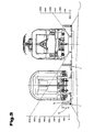
- Fig. 4 to 7 is now the first embodiment of the protection device 1 after Fig. 3 represented, which is arranged centrally between two tracks.
- the protective device 1 in turn comprises a base element 3 and at least one wall element 4, it also being possible to use a plurality of wall elements 4, for example two above the other, as shown in FIG Fig. 7 is shown. Of course, a different number of wall elements 4, which are arranged one above the other, can also be provided in the protective device 1.
- Such a wall element 4 may, for example, have a length of about 3 m, a width of 12 cm and a height of 40 cm, whereby these details are not to be understood as limiting.
- this protection device 1 consists of several parts, so it is not manufactured in one piece, in particular the base element 3 and the wall elements 4 represent separate components of the protection device 1.
- the base element 3 is preferably designed as a concrete base in the form of a flat element as shown in FIGS 4 to 6
- a base element 3 has a width of about 0.84 m, a length of about 3 m and have a height of about 0.12 m, and these embodiments have only exemplary character.
- this base element 3 is formed so that in an intermediate region 15, an at least approximately planar surface 16 is formed, on which the wall elements 4 are arranged, wherein the width of this surface 16 in the direction of the tracks at least approximately equal to the width of the wall elements 4 or can be bigger.
- Side portions 17 of the base member 3 are slightly sloping formed on its upper side to facilitate drainage of water.
- the underside of the base element 3 is made flat in order to achieve a larger footprint and thus a higher stability of the protective device.
- the base element 3 is arranged in this embodiment on a ballast bed of a track, it may be advantageous if on the underside of the base element 3, an elastomeric element, such as a rubber mat, or a fleece is arranged, in which the crushed grains can be partially pressed.
- This elastomer element or fleece can be glued to the underside of the base element 3, it is also possible that it is inserted into the formwork for the production of the concrete element and thus is already connected during manufacture with the concrete base.
- connecting tabs 7 can again be provided in the base element 3, in particular in the middle region 15 on the end faces 5, viewed in the longitudinal direction of the base element 3.
- These connecting straps 7 are preferably cast in turn from steel and into the base element 3, which consists of concrete, that is to say that it has already been inserted into the corresponding shape during the production of the base element 3, whereby a better pull-out strength and a higher adhesive bond is achieved , About this connecting plates 7 a better tensile bond of the juxtaposed and interconnected base elements 3 is achieved.
- the connection can be made, for example, with corresponding brackets which are used in this connection tabs 7, two base elements 3 interconnecting.
- the base element 3 is executed at the end faces 5 slightly cambered. It is thus achieved that in the longitudinal direction of the base element 3 a certain mobility, that is pivotability of two juxtaposed base elements 3 is achieved, so that in particular in the curve region of rails a corresponding replica of the curve radius is made possible.
- the base element 3 viewed in plan view is at least approximately rectangular in shape.
- anchor plates 18 are provided in this embodiment, which are arranged eccentrically and spaced from the two end faces 5.
- These anchor plates 18 may have threaded bolts which project at least approximately vertically upwards to thereby upright elements 19, for example H-beam or I-beam, as is known Fig. 8 it can be seen to be able to connect to the base element 3, in particular via screw connections.
- these anchor plates 18 are in turn cast in the base element 3, that is integrally connected thereto.
- the execution of the upright elements 19 itself can correspond to the state of the art for noise protection walls and, as is known, the wall elements 4 from above into these I and. H-beam used and supported by these.
- Fig. 7 It can be seen, in the context of the invention, the possibility that the base member 3 is connected to a threshold 20 and / or a rail 21 of the track system or connected to this.
- this compound is designed so that a certain relative movement between the base element 3 and threshold 20 and rail 21 is made possible, so no screwing of the base element 3 or the like takes place, although these are of course possible.
- the base element 3 may comprise a connecting element 22, which is in particular made of a metal, for example steel, and which, for example, a width - in the longitudinal direction considered the rail 21 - may have a maximum of the width of the threshold 20 or below.
- This connecting element 22 is arranged on the underside of the base element 3 and preferably such that it surrounds the base element 3 on the side remote from the rail 21, for which purpose this connecting element 22 is bow-shaped in an end region 23.
- a further bracket member 24 is arranged, so that therefore the base member 3 is disposed between these two brackets.
- This bracket member 24 has two in opposite from a base 25 projecting legs 26, 27, wherein the legs 26 in the direction of the bow-shaped end portion 23 of the connecting element 22 and the further leg 27 in the direction of the rail 21 and wherein this further leg 27th may be bolted to the connecting element 22 via a corresponding device.
- this bracket member 24 has two in opposite from a base 25 projecting legs 26, 27, wherein the legs 26 in the direction of the bow-shaped end portion 23 of the connecting element 22 and the further leg 27 in the direction of the rail 21 and wherein this further leg 27th may be bolted to the connecting element 22 via a corresponding device.
- another connection technique for example, a welding of this bracket member 24 with
- the connecting element 22 may be screwed to the threshold 20.
- Fig. 7 it is shown that the rail 21 is arranged on a further connecting element 28, which in turn is formed bow-shaped on its side facing away from the base element and thus engages around a rail 29 on one side.
- the connecting element 22 On the side facing the base element 3 of the rail 21, the connecting element 22 is bent with two standing at an obtuse angle legs 30, 31, said two legs 30, 31 exert a "spring force" on the rail 21, so on the one hand, the rail 21st in it rests on the other hand, in turn, a certain relative movement of the rail 21 to the base element 3 is made possible.
- the connecting element 22 is screwed in particular to the further connecting element 28, wherein this further connecting element 28 can be screwed to the threshold 20, if necessary via the same screw connection with which also the connecting element 22 is screwed to the further connecting element 28.
- this further connecting element 28 can be screwed to the threshold 20, if necessary via the same screw connection with which also the connecting element 22 is screwed to the further connecting element 28.
- the further connecting element 28 in the case that the threshold 20 is made of a concrete body, is poured into this.
- the latter may be provided in the region of the two longitudinal side edges 32, 33 with a deposition 34, 35.
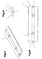
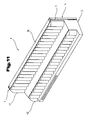
- Fig. 8 to 10 is that variant of the protective device 1 after Fig. 3 represented, which in the side areas of a track, so not between two tracks, is arranged.
- the base element 3 corresponds to that of the embodiment described above and in turn is cast in particular of concrete and designed as a flat element, but may have a smaller width, for example, a width of 0.5 m. Also, this base element 3 in turn has the connecting plates 7 and the anchor plates 18, as described above, on, the latter being not arranged in a central region, but in the region of one of the longitudinal side edges 32, 33rd
- connection of the base element 3 to the rail 21 and / or the threshold 20 is possible and the base element 3 in cross-section with the depositions 34, 35 may be formed according to how this Fig. 9 is apparent.
- the described arrangement of the anchor plates 18 ensures that the wall elements 4 can be arranged to overlap two adjoining base elements 3, whereby the composite within the protective wall system 2 can be improved.
- the base element 3 has a length in the direction of the track extension which at least approximately corresponds to the length of the wall elements in the same direction.
- the anchor plates 18 and thus also the carrier elements 19 in the region of the end faces 5 of the base element 3 are arranged.
- these end faces 5 can be made slightly rounded. It is generally the case with the base element 3 but also the possibility to provide a straight, oblique surface instead of a rounding.
- At least one support element is arranged, wherein this support element can be connected to the base element 3.
- corresponding anchor plates can also be provided for this purpose.
- the base element 3 is preferably not anchored in the ground.
- Fig. 11 and 12 show an embodiment variant of the protective device 1, wherein in these representations in each case an element is shown.
- This element in turn comprises the base element 3 and the wall element 4, which are, however, preferably integrally connected to a component 36, and in particular made of concrete as a one-piece molded part.
- this component 36 has a multiple, in the illustrated variant two-fold, gradation the base element 3 has the largest width of the component 36.
- the wall element 4 adjoins upward to extend.
- the component 36 is formed with a smaller width than the base element 3 and with a larger width than the wall element in the upper region, so that the component 36 has a stepped profile.
- damping elements 39, 40 are arranged, in particular connected to the concrete element, for example glued, screwed, connected by positive engagement, cast on the concrete, etc.
- damping elements 39, 40 have an at least approximately trapezoidal cross-section, but may also have a different cross-sectional shape, for example rectangular, etc.
- no such damping element in the Figure 11 and 12 is shown, of course, this may also be attached to a damping element pointing towards the noise source.
- the damping elements 39, 40 may be made of rubber, in particular of a rubber granulate, preferably from used tires, wherein the granules may be connected to each other with a corresponding binder, for example an adhesive, preferably a lightweight concrete.
- the damping elements 39, 40 may also consist entirely of rubber.
- a noise source facing surface 41 and 42 may be provided with a.99.shvkturtechnik, for example in the manner of a wave as shown, with other forms of surface structuring are possible.
- connection of the component to the track superstructure of a rail can, as described via not shown fasteners 22, so-called rail bracket done, which are on the one hand connected to the base element 3, for example, screwed to the pointing to the noise source surface of the base element 3, and on the other can be connected to the rail element or adjacent to this.
- connection tabs 7 In the area of the vertical end faces of the component 36, the connection tabs 7 already described are arranged, via which components 36 standing next to one another can be connected to one another.
- the device 36 can also be freestanding, without foundation, placed.
- Fig. 7 shown soundproofing element of this embodiment according to the Fig. 11 and 12 be formed accordingly, ie with a one-piece component 36 which in this case has a T-shaped cross section, on which optionally a step profile is formed and on which optionally, as described, additional damping elements 39, 40 can be arranged.
- a further embodiment of the protective device 1 is shown in side view.
- This comprises the base element 3 and the wall element 4 arranged thereon.
- an additional soundproofing element 43 is arranged on the wall element 4 at a distance from the wall element 4 and connected thereto via connecting elements 44, for example metal hoops.
- This soundproofing element 43 may be formed, for example, as a rubber mat 45, in particular made of rubber granules, which is at least partially surrounded by an enveloping element 46, in particular of a metallic material, for example aluminum, in order to give the rubber mat 45 the required stability.
- the soundproofing element 43 is preferably arranged projecting in the installed position to the rear over the wall element, as shown in Fig. 13 is shown.
- recesses in particular longitudinal grooves, can be arranged in the wall element, into which an end region of the connecting elements 44 as in FIG Fig. 13 shown engaged.
- soundproofing elements 43 can also be arranged in the embodiments of the protective device 1 described above.
- the damping element 39 may be arranged on the base element 3, as shown.
- connection to the track can be done as described via connecting elements 27.
Landscapes
- Engineering & Computer Science (AREA)
- Architecture (AREA)
- Civil Engineering (AREA)
- Structural Engineering (AREA)
- Life Sciences & Earth Sciences (AREA)
- Sustainable Development (AREA)
- Devices Affording Protection Of Roads Or Walls For Sound Insulation (AREA)
- Refuge Islands, Traffic Blockers, Or Guard Fence (AREA)
- Road Signs Or Road Markings (AREA)
Applications Claiming Priority (1)
| Application Number | Priority Date | Filing Date | Title |
|---|---|---|---|
| AT0113809A AT508575B1 (de) | 2009-07-21 | 2009-07-21 | Schutzvorrichtung |
Publications (2)
| Publication Number | Publication Date |
|---|---|
| EP2278072A2 true EP2278072A2 (fr) | 2011-01-26 |
| EP2278072A3 EP2278072A3 (fr) | 2015-09-02 |
Family
ID=42797438
Family Applications (1)
| Application Number | Title | Priority Date | Filing Date |
|---|---|---|---|
| EP10007539.9A Withdrawn EP2278072A3 (fr) | 2009-07-21 | 2010-07-21 | Dispositif de protection |
Country Status (2)
| Country | Link |
|---|---|
| EP (1) | EP2278072A3 (fr) |
| AT (1) | AT508575B1 (fr) |
Cited By (6)
| Publication number | Priority date | Publication date | Assignee | Title |
|---|---|---|---|---|
| WO2013049814A1 (fr) * | 2011-09-30 | 2013-04-04 | Zimmerman Donald Robert | Barrière acoustique |
| AT512391A4 (de) * | 2011-11-22 | 2013-08-15 | Art Asamer Rubber Technology Gmbh | Lärmschutzvorrichtung |
| WO2014006144A1 (fr) * | 2012-07-04 | 2014-01-09 | Hering Bau Gmbh & Co. Kg | Unité de protection acoustique et sa structure |
| EP2295643B1 (fr) * | 2009-09-15 | 2014-03-26 | Melba Products Limited | Barrière de contrôle |
| CN104169500A (zh) * | 2011-11-22 | 2014-11-26 | Art阿萨玛橡胶技术有限公司 | 噪音防护装置 |
| CN114086494A (zh) * | 2021-11-29 | 2022-02-25 | 九江学院 | 基于交通设计的安全分隔栏 |
Families Citing this family (3)
| Publication number | Priority date | Publication date | Assignee | Title |
|---|---|---|---|---|
| DE202011052057U1 (de) | 2011-11-22 | 2011-12-30 | Art Asamer Rubber Technology Gmbh | Lärmschutzvorrichtung |
| DE202013005490U1 (de) * | 2013-06-19 | 2014-09-23 | Eurovia Beton Gmbh | Trennmodul für ein Fahrspurtrennsystem |
| CN114032814A (zh) * | 2021-12-22 | 2022-02-11 | 潍坊学院 | 安全降噪隔离墩 |
Citations (4)
| Publication number | Priority date | Publication date | Assignee | Title |
|---|---|---|---|---|
| EP0596405A1 (fr) * | 1992-11-03 | 1994-05-11 | Peter Rausch | Barrière de route avec un socle en béton |
| EP0931879A1 (fr) * | 1998-01-23 | 1999-07-28 | Colas | Dispositif de protection routière et procédé de réalisation d'un tel dispositif |
| EP1455018A1 (fr) * | 2003-03-06 | 2004-09-08 | Maas GmbH | Mur anti-bruit |
| KR20090027020A (ko) * | 2007-09-11 | 2009-03-16 | 주식회사 태창닛케이 | 흡음기능을 가진 방음벽 지주 |
Family Cites Families (5)
| Publication number | Priority date | Publication date | Assignee | Title |
|---|---|---|---|---|
| CA2104311C (fr) * | 1993-08-18 | 2000-10-31 | Guenter Baatz | Pare-choc en caoutchouc pour vehicule |
| DE29807232U1 (de) * | 1997-04-23 | 1998-08-27 | MAIBACH Verkehrssicherheits- und Lärmschutzeinrichtungen GmbH, 73037 Göppingen | Leitwand zur Sicherung von Go-Kart Bahnen |
| IT1310668B1 (it) * | 1999-08-03 | 2002-02-19 | Eleonora Fasano | Mensola di supporto collegata con attacco meccanico a rotaiaferroviaria impegnata a traversina. |
| AU2097401A (en) * | 1999-12-21 | 2001-07-03 | Yodock Wall Company, Inc., The | Apparatus for covering vehicle traffic dividers |
| DE10016105A1 (de) * | 2000-03-31 | 2001-10-04 | Bahnbau Wels Gmbh Wels | Gleis für Schienenfahrzeuge insbesondere in fester Fahrbahn |
-
2009
- 2009-07-21 AT AT0113809A patent/AT508575B1/de not_active IP Right Cessation
-
2010
- 2010-07-21 EP EP10007539.9A patent/EP2278072A3/fr not_active Withdrawn
Patent Citations (4)
| Publication number | Priority date | Publication date | Assignee | Title |
|---|---|---|---|---|
| EP0596405A1 (fr) * | 1992-11-03 | 1994-05-11 | Peter Rausch | Barrière de route avec un socle en béton |
| EP0931879A1 (fr) * | 1998-01-23 | 1999-07-28 | Colas | Dispositif de protection routière et procédé de réalisation d'un tel dispositif |
| EP1455018A1 (fr) * | 2003-03-06 | 2004-09-08 | Maas GmbH | Mur anti-bruit |
| KR20090027020A (ko) * | 2007-09-11 | 2009-03-16 | 주식회사 태창닛케이 | 흡음기능을 가진 방음벽 지주 |
Cited By (7)
| Publication number | Priority date | Publication date | Assignee | Title |
|---|---|---|---|---|
| EP2295643B1 (fr) * | 2009-09-15 | 2014-03-26 | Melba Products Limited | Barrière de contrôle |
| WO2013049814A1 (fr) * | 2011-09-30 | 2013-04-04 | Zimmerman Donald Robert | Barrière acoustique |
| AT512391A4 (de) * | 2011-11-22 | 2013-08-15 | Art Asamer Rubber Technology Gmbh | Lärmschutzvorrichtung |
| AT512391B1 (de) * | 2011-11-22 | 2013-08-15 | Art Asamer Rubber Technology Gmbh | Lärmschutzvorrichtung |
| CN104169500A (zh) * | 2011-11-22 | 2014-11-26 | Art阿萨玛橡胶技术有限公司 | 噪音防护装置 |
| WO2014006144A1 (fr) * | 2012-07-04 | 2014-01-09 | Hering Bau Gmbh & Co. Kg | Unité de protection acoustique et sa structure |
| CN114086494A (zh) * | 2021-11-29 | 2022-02-25 | 九江学院 | 基于交通设计的安全分隔栏 |
Also Published As
| Publication number | Publication date |
|---|---|
| EP2278072A3 (fr) | 2015-09-02 |
| AT508575A1 (de) | 2011-02-15 |
| AT508575B1 (de) | 2011-06-15 |
Similar Documents
| Publication | Publication Date | Title |
|---|---|---|
| EP2278072A2 (fr) | Dispositif de protection | |
| DE69301857T2 (de) | Leitplanken aus Holz und Metall | |
| EP2644776B1 (fr) | Paroi de protection | |
| EP1762660B1 (fr) | Dispositif de guidage routier | |
| EP2817457B1 (fr) | Dispositif anti-bruit | |
| EP2567029B1 (fr) | Système de retenue pour véhicules au niveau de la chaussée | |
| WO2012062415A1 (fr) | Arrangement de poteau pour une construction de barrière de sécurité et construction de barrière de sécurité pour la sécurisation des voies de circulation sur des ouvrages | |
| EP2158363B1 (fr) | Système de retenue de véhicules rempli ou remplissable destiné à délimiter des voies de circulation | |
| DE2442660A1 (de) | Elastomeres eisenbahnschienenkreuzungselement | |
| EP2218826A2 (fr) | Rail de guidage | |
| DE202012104881U1 (de) | Barriereelement und Barriere aus zumindest zwei miteinander verbundenen Barriereelementen | |
| EP2126218B1 (fr) | Absorbeur de bruit avec profilés de support | |
| DE202011052057U1 (de) | Lärmschutzvorrichtung | |
| DE102007024993A1 (de) | Fahrzeug-Rückhaltesystem an Verkehrswegen | |
| DE202006020863U1 (de) | Verkehrs-Leit-Einrichtung | |
| DE202010000658U1 (de) | Schutzplankenanordnung | |
| DE202008003111U1 (de) | Fahrzeugrückhaltesystem mit vergrößerter Auflagefläche zum Begrenzen von Fahrbahnen | |
| DE102007063511A1 (de) | Schutzeinrichtung an Verkehrswegen | |
| DE102009028904A1 (de) | Leitplanke oder Schutzplanke, bestehend aus einem einzigen Element oder aus mehreren in Längsrichtung aneinandergekoppelten Elementen | |
| AT268359B (de) | Gleisunterlage | |
| DE102011100183A1 (de) | Fahrzeugrückhaltesystem mit verbessertemDeformationsverhalten | |
| EP2567030A1 (fr) | Glissière de sécurité | |
| DE102007042392A1 (de) | Leiteinrichtung an Verkehrswegen mit zwei Rückhaltesystemen unterschiedlicher Steifigkeit und einer Übergangskonstruktion zwischen diesen | |
| AT512391B1 (de) | Lärmschutzvorrichtung | |
| EP2952630B1 (fr) | Système de retenue de véhicule |
Legal Events
| Date | Code | Title | Description |
|---|---|---|---|
| PUAI | Public reference made under article 153(3) epc to a published international application that has entered the european phase |
Free format text: ORIGINAL CODE: 0009012 |
|
| AK | Designated contracting states |
Kind code of ref document: A2 Designated state(s): AL AT BE BG CH CY CZ DE DK EE ES FI FR GB GR HR HU IE IS IT LI LT LU LV MC MK MT NL NO PL PT RO SE SI SK SM TR |
|
| AX | Request for extension of the european patent |
Extension state: BA ME RS |
|
| RAP1 | Party data changed (applicant data changed or rights of an application transferred) |
Owner name: ART ASAMER RUBBER TECHNOLOGY GMBH |
|
| RAP1 | Party data changed (applicant data changed or rights of an application transferred) |
Owner name: SARANUS BETEILIGUNGSVERWALTUNGS GMBH |
|
| PUAL | Search report despatched |
Free format text: ORIGINAL CODE: 0009013 |
|
| AK | Designated contracting states |
Kind code of ref document: A3 Designated state(s): AL AT BE BG CH CY CZ DE DK EE ES FI FR GB GR HR HU IE IS IT LI LT LU LV MC MK MT NL NO PL PT RO SE SI SK SM TR |
|
| AX | Request for extension of the european patent |
Extension state: BA ME RS |
|
| RIC1 | Information provided on ipc code assigned before grant |
Ipc: E01F 15/08 20060101ALI20150727BHEP Ipc: E01F 8/00 20060101AFI20150727BHEP Ipc: E01B 19/00 20060101ALI20150727BHEP Ipc: E01F 15/10 20060101ALI20150727BHEP |
|
| 17P | Request for examination filed |
Effective date: 20160211 |
|
| RAX | Requested extension states of the european patent have changed |
Extension state: ME Extension state: BA Extension state: RS Payment date: 20160211 |
|
| RBV | Designated contracting states (corrected) |
Designated state(s): AL AT BE BG CH CY CZ DE DK EE ES FI FR GB GR HR HU IE IS IT LI LT LU LV MC MK MT NL NO PL PT RO SE SI SK SM TR |
|
| 17Q | First examination report despatched |
Effective date: 20161205 |
|
| STAA | Information on the status of an ep patent application or granted ep patent |
Free format text: STATUS: THE APPLICATION IS DEEMED TO BE WITHDRAWN |
|
| 18D | Application deemed to be withdrawn |
Effective date: 20170419 |