EP2278074A2 - Dispositif de raccordement pour un compteur de courant - Google Patents
Dispositif de raccordement pour un compteur de courant Download PDFInfo
- Publication number
- EP2278074A2 EP2278074A2 EP10006126A EP10006126A EP2278074A2 EP 2278074 A2 EP2278074 A2 EP 2278074A2 EP 10006126 A EP10006126 A EP 10006126A EP 10006126 A EP10006126 A EP 10006126A EP 2278074 A2 EP2278074 A2 EP 2278074A2
- Authority
- EP
- European Patent Office
- Prior art keywords
- suction
- suction head
- leaf
- sweeping
- sweeper according
- Prior art date
- Legal status (The legal status is an assumption and is not a legal conclusion. Google has not performed a legal analysis and makes no representation as to the accuracy of the status listed.)
- Withdrawn
Links
Images


Classifications
-
- E—FIXED CONSTRUCTIONS
- E01—CONSTRUCTION OF ROADS, RAILWAYS, OR BRIDGES
- E01H—STREET CLEANING; CLEANING OF PERMANENT WAYS; CLEANING BEACHES; DISPERSING OR PREVENTING FOG IN GENERAL CLEANING STREET OR RAILWAY FURNITURE OR TUNNEL WALLS
- E01H1/00—Removing undesirable matter from roads or like surfaces, with or without moistening of the surface
- E01H1/08—Pneumatically dislodging or taking-up undesirable matter or small objects; Drying by heat only or by streams of gas; Cleaning by projecting abrasive particles
- E01H1/0827—Dislodging by suction; Mechanical dislodging-cleaning apparatus with independent or dependent exhaust, e.g. dislodging-sweeping machines with independent suction nozzles ; Mechanical loosening devices working under vacuum
-
- A—HUMAN NECESSITIES
- A01—AGRICULTURE; FORESTRY; ANIMAL HUSBANDRY; HUNTING; TRAPPING; FISHING
- A01G—HORTICULTURE; CULTIVATION OF VEGETABLES, FLOWERS, RICE, FRUIT, VINES, HOPS OR SEAWEED; FORESTRY; WATERING
- A01G20/00—Cultivation of turf, lawn or the like; Apparatus or methods therefor
- A01G20/40—Apparatus for cleaning the lawn or grass surface
- A01G20/43—Apparatus for cleaning the lawn or grass surface for sweeping, collecting or disintegrating lawn debris
- A01G20/47—Vacuum or blower devices
Definitions
- the present invention relates to a self-propelled pick-up sweeper having a carrier vehicle, a sweeper unit and a sweep-receiving unit according to the preamble of claim 1.
- Such sweepers are known in various configurations.
- generic sweepers in the form of so-called compact sweepers and sweeper machines are in use.
- Disclosed are generic sweeping machines, for example in the DE 29901362 U1 and the US 4554701 , the disclosure of which is incorporated by reference into the content of the present application.
- the cleaning performance can not be negligible in known generic sweeping machines, because the materials concerned the so-called. "Leaf" more or Add less and thus can obstruct the sweeping air flow through the sweep receiving unit. If, due to a corresponding loading of the leaf screen, a considerable loss of cleaning performance occurs, the leaf screen is cleaned. This is done in practice, typically by hand or by means of a broom, the driver through a side at the sweeping material collecting container attached cleaning door into the container interior. It has also already been proposed (cf.
- the leaf strainers generic sweeping machines are typically still cleaned by hand, wherein, to increase the corresponding cleaning intervals, the surface of the leaf strainers is chosen to be as large as possible, in particular by staircase or zigzag folded leaf strainers.
- the present invention has set itself the task of providing a generic self-propelled picking sweeper, with a high ease of use for the driver or operator the decrease in cleaning performance can be effectively counteracted by the above-indicated relationships.
- this object is achieved in that in a self-propelled picking sweeper of the generic type the leaf screen on the inflow side is associated with a relative to this moving suction head.
- the on the inflow side adhering to the leaf sieve, collected by this sweeping hereinafter referred to with respect to its surface light weight referred to as "light”, continuously or optionally as needed intermittently removed and the leaf screen in this way "regenerated” , so that the sweeper unfolds the full cleaning performance at all times.
- the said continuous cleaning operation by means of a constantly - typically relatively slowly, for example between 1- and 5 times per minute - over the leaf sieve moving suction head is particularly advantageous because it constantly counteracts a buildup of light matter contamination or -Verstopfung the leaf screen. In this mode of operation, removal of larger amounts of light material from the leaf screen is thus not required. This is also particularly advantageous because in this way a comparatively low negative pressure on the suction head is sufficient to achieve the desired cleaning effect.
- the suction head is driven to rotate or to oscillate, the oscillating movement being in particular in the form of a rectilinear movement of the suction head along at least one guide extending parallel to the leaf screen or else about an axis can be executed pivotable oscillating.
- This is favorable both in terms of reliability and in terms of a comparatively simple drive for the movement of the suction head.
- An advantageous effect of the rotating or pivotally oscillating movement the suction head is the most favorable and reliable supply of the required vacuum at the suction head by a suction hose is connected via a rotary coupling to this.
- a separate motor e.g., electric motor, hydraulic motor
- the suction head is designed as a suction bar, in particular with a substantially rectangular or trapezoidally elongated inlet cross-section of the suction head in the region of its mouth.
- the inlet cross section of the suction head in the region of the mouth thereof is preferably substantially smaller than the cross section of the leaf sieve through which flows. In this sense, it can for example make up between 4% and 20% of the effective flow cross section of the associated leaf screen.
- the dimensioning in detail depends, for example, on the manner in which the light goods of the leaf wire suctioning flow through the suction head is effected.
- too small a cross-sectional area at the mouth of the suction head is unfavorable.
- the suction head dispensing with a separate suction fan, is connected via a suction hose to the sweeping material intake tract upstream of the leaf sieve, in particular to the suction channel of the intake tract.
- the suction hose is connected to a suction channel with respect to the passage cross-section of the leaf screen small flow cross-section;
- the flow cross section of the suction channel in the region of the mouth of the suction hose in this between 8% and 30% of the passage cross-section of the leaf screen amount is provided.
- the leaf sieve downstream is associated with a cover which moves relative to the latter and cooperates with the suction head, which cover in particular the suction head and with this coupled can be moved.
- the extent of the said cover parallel to the leaf screen can correspond in particular substantially to the extent of the associated suction head. Inexpensive, however, is a certain overhang of the cover relative to the mouth cross-section of the suction head.
- the cover is particularly preferred only in a central region relatively dense (downstream) on the leaf screen, while beveled edges project obliquely from the leaf sieve; This results in particularly favorable, the cleaning performance positively influencing flow conditions in the form of a return flow in the direction of the suction head.
- the removal of light material attached to the leaf wire on the inflow side can be assisted by the suction head comprising one or more stripper (s) fitting on the leaf screen.
- the latter can for example also be designed in the form of stripper brushes. It is a control of the movement speed of the suction head relative to the leaf screen such conceivable that for the mechanical removal of light material from the leaf screen by means of at least one scraper, a higher speed is selected than for the pneumatic removal of the remaining contaminants by means of the suction head. This can extend to active use, in particular of the centrifugal force during mechanical cleaning of the leaf screen, by means of the at least one scraper rotating relatively quickly together with the associated suction head.
- the present invention is particularly suitable for receiving sweeping machines, the sweeping material collecting container having a single deposition chamber, wherein the leaf screen is arranged in this case in the region of the suction air outlet from the debris collection container.
- the present invention can be applied, for example, in sweepers in which the leaf sieve a first separation chamber of the waste collection from a downstream arranged second separation chamber, which can serve in particular the separation of fine dust separates.
- the sweeper may finally have a plurality of flow lines arranged parallel to each other leaf strainers, which in each case in accordance with the invention an inflow relative to this moving suction head is assigned, in which case particularly preferably the two (or more) leaf strainers assigned Suction heads are operated alternately.
- the cleaning of the various leaf strainers takes place in this case alternately, which is particularly advantageous in terms of the efficiency of Laubsiebgraphy. Because the effect effective removal of inflow on the leaf screen adhering light goods effective pressure gradient in the region of the associated suction head can be maximized in this way.
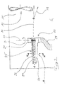
- the illustrated in the drawing self-propelled picking sweeper 1 comprises in known as such and therefore not explained in depth here a carrier vehicle 2, a running with a rotating brush 3 swept unit 4 and a debris pickup unit 5.
- the latter in turn includes a Kehrgut- Sump 6, in which a sweeping material intake tract 7 opens with a suction mouth 8 and a suction channel 9, and a suction fan 10.
- suction fan 10 causes an air flow A through the suction port 8, the suction channel 9 and the debris collection container 6, wherein opposite the mouth 12 of the suction channel 9 in the debris collection container 6, a baffle plate 13 and in the region of the connection of the exhaust duct 11 to the debris collection container 6 a leaf screen 14 is arranged and the exhaust air leaves the exhaust duct 11 through an outlet 15 ,
- the suction channel 9 is in two parts executed with a lower portion 16 and an integral with the debris collecting container 6 upper portion 17, wherein further the debris collecting container 6 is closed at its rear end by an upwardly pivotable (arrow C) flap 18.
- the rigid, i. relative to the debris collecting container 6 non-movable leaf sieve 14 is a suction head 19 associated with the inflow side.
- This is designed as a suction bar 20, the mouth of which is opposite the leaf sieve 14 at a small distance and which is movable relative to the leaf sieve 14 by means of the drive motor 21 to the leaf 14 perpendicular to the axis 22 is rotatable (arrow D).
- the suction bar 20 is connected via a rotary coupling 23 and a suction hose 24 to the suction channel 9 - namely its upper portion 17 - wherein - in the interest of the possibility of intermittent cleaning of the leaf screen 14 by means of the suction head 19 - in the rotary coupling 23, if necessary, a controllable Barrier can be integrated.
- the leaf screen 14 is a downstream relative to this moving, the suction head 19 opposite, associated with this and associated with this rotating about the axis 22 cover 25 which cooperates with the suction head 19 so that it flows back through the leaf screen 14 in the Area of the suction head specifically influenced and in this way the voltage applied to the suction head vacuum for collecting concentrated by the inflow side of the leaf screen 14 adhering light goods.
- the cover 25 is - in the direction of movement of the suction head 20 and cover 25 - wider than the suction head. It includes a relatively close to the leaf screen 14 adjacent central portion 26 and two beveled, obliquely away from the leaf strainer Randberreiche 27. The removal of light material from the leaf strainer by means of the suction head is supported by a - not graphically illustrated - scraper, which on the Suction head is arranged and abuts the leaf screen 14 on the inflow side.
- the respective associated suction heads 19 are preferably operated alternately, for which purpose appropriate barriers are provided, by means of which the suction heads alternately acted upon by connection to the suction channel 9 with negative pressure are.
Landscapes
- Life Sciences & Earth Sciences (AREA)
- Environmental Sciences (AREA)
- Engineering & Computer Science (AREA)
- Architecture (AREA)
- Civil Engineering (AREA)
- Structural Engineering (AREA)
- Cleaning In General (AREA)
- Combined Means For Separation Of Solids (AREA)
Applications Claiming Priority (1)
| Application Number | Priority Date | Filing Date | Title |
|---|---|---|---|
| DE102009029956A DE102009029956A1 (de) | 2009-06-19 | 2009-06-19 | Selbstfahrende aufnehmende Kehrmaschine |
Publications (1)
| Publication Number | Publication Date |
|---|---|
| EP2278074A2 true EP2278074A2 (fr) | 2011-01-26 |
Family
ID=42664639
Family Applications (1)
| Application Number | Title | Priority Date | Filing Date |
|---|---|---|---|
| EP10006126A Withdrawn EP2278074A2 (fr) | 2009-06-19 | 2010-06-14 | Dispositif de raccordement pour un compteur de courant |
Country Status (2)
| Country | Link |
|---|---|
| EP (1) | EP2278074A2 (fr) |
| DE (1) | DE102009029956A1 (fr) |
Cited By (6)
| Publication number | Priority date | Publication date | Assignee | Title |
|---|---|---|---|---|
| CN104278651A (zh) * | 2013-07-01 | 2015-01-14 | 胡煜 | 清理痰液机 |
| WO2017041769A1 (fr) * | 2015-09-13 | 2017-03-16 | 杨丁香 | Véhicule de nettoyage de parc de grande taille |
| CN106759021A (zh) * | 2016-12-30 | 2017-05-31 | 太仓韬信信息科技有限公司 | 一种道路清扫装置 |
| CN108060650A (zh) * | 2017-12-25 | 2018-05-22 | 姚森 | 无尘防结冰市政道路清洁系统 |
| CN108385577A (zh) * | 2017-02-02 | 2018-08-10 | 陈颜开 | 一种市政环卫专用的烘干机械 |
| CN108442291A (zh) * | 2018-03-20 | 2018-08-24 | 宿州大地网络科技有限公司 | 一种用于杨絮收集并将其压缩入袋的装置及方法 |
Families Citing this family (5)
| Publication number | Priority date | Publication date | Assignee | Title |
|---|---|---|---|---|
| DE102012103381A1 (de) | 2012-04-18 | 2013-10-24 | Rodinia Technologies Ltd. | Vorrichtung zur Reinigung von Wand- oder Bodenflächen |
| DE202015102683U1 (de) | 2015-05-26 | 2015-06-10 | Kugelmann Maschinenbau E.K. | Kehrmaschine |
| EP4054393A1 (fr) | 2019-11-07 | 2022-09-14 | Alfred Kärcher SE & Co. KG | Machine de nettoyage de sol et procédé de fonctionnement d'une machine de nettoyage de sol |
| CN112030848B (zh) * | 2020-09-15 | 2021-11-02 | 济宁学院 | 一种落叶清扫装置 |
| CN113356115B (zh) * | 2021-05-27 | 2022-10-18 | 重庆水利电力职业技术学院 | 一种节能环保建筑土木工程用道路粉尘吸收装置 |
Citations (5)
| Publication number | Priority date | Publication date | Assignee | Title |
|---|---|---|---|---|
| DE2030150A1 (de) | 1969-06-26 | 1971-01-07 | Le Materiel De Voire, Courbevoie (Frankreich) | Vorrichtung zum Reinigen der FiI tersiebe der Ansaugeinrichtung einer mit Saugwirkung arbeitenden Straßen reinigungsmaschine |
| US4554701A (en) | 1984-02-10 | 1985-11-26 | Raaij Karel W M Van | Vacuum street sweeper and filter apparatus therefor |
| DE8613829U1 (de) | 1986-05-22 | 1986-09-04 | Ing. Alfred Schmidt Gmbh, 7822 St Blasien | Straßenkehrmaschine |
| DE9302250U1 (de) | 1993-02-17 | 1993-05-19 | Schörling GmbH & Co Waggonbau, 3000 Hannover | Straßenkehrfahrzeug mit einer Saugvorrichtung |
| DE29901362U1 (de) | 1999-01-27 | 1999-05-06 | Schmidt Holding Europe GmbH, 79837 St Blasien | Aufnehmende Kehrmaschine |
Family Cites Families (3)
| Publication number | Priority date | Publication date | Assignee | Title |
|---|---|---|---|---|
| DD153215A1 (de) * | 1980-07-29 | 1981-12-30 | Heinrich Ruttge | Vorrichtung zur reinigung von schmutzdurchsetzter luft bei strassenreinigungsmaschinen |
| US4373227A (en) * | 1980-09-09 | 1983-02-15 | Tennant Company | Surface maintenance equipment |
| DE8711833U1 (de) * | 1986-11-21 | 1987-10-22 | "Stäfa" Ventilator AG, Stäfa | Filteranlage für Feststoffe |
-
2009
- 2009-06-19 DE DE102009029956A patent/DE102009029956A1/de not_active Withdrawn
-
2010
- 2010-06-14 EP EP10006126A patent/EP2278074A2/fr not_active Withdrawn
Patent Citations (5)
| Publication number | Priority date | Publication date | Assignee | Title |
|---|---|---|---|---|
| DE2030150A1 (de) | 1969-06-26 | 1971-01-07 | Le Materiel De Voire, Courbevoie (Frankreich) | Vorrichtung zum Reinigen der FiI tersiebe der Ansaugeinrichtung einer mit Saugwirkung arbeitenden Straßen reinigungsmaschine |
| US4554701A (en) | 1984-02-10 | 1985-11-26 | Raaij Karel W M Van | Vacuum street sweeper and filter apparatus therefor |
| DE8613829U1 (de) | 1986-05-22 | 1986-09-04 | Ing. Alfred Schmidt Gmbh, 7822 St Blasien | Straßenkehrmaschine |
| DE9302250U1 (de) | 1993-02-17 | 1993-05-19 | Schörling GmbH & Co Waggonbau, 3000 Hannover | Straßenkehrfahrzeug mit einer Saugvorrichtung |
| DE29901362U1 (de) | 1999-01-27 | 1999-05-06 | Schmidt Holding Europe GmbH, 79837 St Blasien | Aufnehmende Kehrmaschine |
Cited By (8)
| Publication number | Priority date | Publication date | Assignee | Title |
|---|---|---|---|---|
| CN104278651A (zh) * | 2013-07-01 | 2015-01-14 | 胡煜 | 清理痰液机 |
| WO2017041769A1 (fr) * | 2015-09-13 | 2017-03-16 | 杨丁香 | Véhicule de nettoyage de parc de grande taille |
| CN106759021A (zh) * | 2016-12-30 | 2017-05-31 | 太仓韬信信息科技有限公司 | 一种道路清扫装置 |
| CN108385577A (zh) * | 2017-02-02 | 2018-08-10 | 陈颜开 | 一种市政环卫专用的烘干机械 |
| CN108060650A (zh) * | 2017-12-25 | 2018-05-22 | 姚森 | 无尘防结冰市政道路清洁系统 |
| CN108060650B (zh) * | 2017-12-25 | 2019-08-23 | 唐山正元管业有限公司 | 无尘防结冰市政道路清洁系统 |
| CN108442291A (zh) * | 2018-03-20 | 2018-08-24 | 宿州大地网络科技有限公司 | 一种用于杨絮收集并将其压缩入袋的装置及方法 |
| CN108442291B (zh) * | 2018-03-20 | 2020-06-02 | 宿州大地网络科技有限公司 | 一种用于杨絮收集并将其压缩入袋的装置及方法 |
Also Published As
| Publication number | Publication date |
|---|---|
| DE102009029956A1 (de) | 2010-12-23 |
Similar Documents
| Publication | Publication Date | Title |
|---|---|---|
| EP2278074A2 (fr) | Dispositif de raccordement pour un compteur de courant | |
| DE69224666T2 (de) | Teppichreinigungsmaschine für teilchenbeseitigung | |
| DE102012023856B4 (de) | Ansaugmodul eines Luftansaugtrakts einer Brennkraftmaschine | |
| DE2857873C2 (de) | Abzugshaube für eine fahrbare Kehrmaschine | |
| EP2256250B1 (fr) | Dispositif mobile destiné à enlever des produits de remplissage d'une surface | |
| DE2545137A1 (de) | Saugreinigungsvorrichtung | |
| DE10037780B4 (de) | Kehreinrichtung | |
| EP1380246A2 (fr) | Aspirateur utilisé à des fins de nettoyage | |
| EP2734098B1 (fr) | Balayeuse avec conteneur sous pression pour le nettoyage du filtre | |
| EP1626647A1 (fr) | Aspirateur comprenant un dispositif de nettoyage a air comprime destine au nettoyage d'un filtre ceramique | |
| DE1264477B (de) | Filtersystem fuer Kehrmaschinen | |
| DE4330233C2 (de) | Kehrmaschine | |
| EP2568081B1 (fr) | Dispositif de nettoyage destiné à nettoyer les surfaces de sol artificielles dotées de particules de revêtement de sol, en particulier les gazons artificiels | |
| EP4132336A2 (fr) | Unité de filtre pour une machine de nettoyage, machine de nettoyage du sol et procédé de fonctionnement d'une machine de nettoyage du sol | |
| EP1535564A2 (fr) | Machine à nettoyer les sols | |
| WO2011107502A2 (fr) | Dispositif et procédé pour nettoyer un filtre à air de véhicule, et dispositif de refroidissement associé | |
| DE102019125002A1 (de) | Saugroboter und Verfahren zum Betrieb eines Saugroboters | |
| DE925777C (de) | Verfahren zur selbsttaetigen Beseitigung von Strassenschmutz und Strassenreinigungskraftfahrzeug | |
| DE10342117B4 (de) | Selbstfahrende Kehrsaugmaschine mit einer Filtereinrichtung zum Abscheiden von nassem oder trockenem Kehricht | |
| DE102010043159B4 (de) | Staubsauger mit einem Fliehkraftabscheider | |
| DE69106515T2 (de) | Reinigungs- und andere fahrzeuge. | |
| EP2821553A1 (fr) | Machine de nettoyage du sol ayant un élément de brosse installé dans un bac de rétention | |
| DE202008014127U1 (de) | Filteranordnung für ein Flächenreinigungsfahrzeug und Flächenreinigungsfahrzeug | |
| DE9420899U1 (de) | Kehrgerät | |
| DE202024106469U1 (de) | Kehrmaschine |
Legal Events
| Date | Code | Title | Description |
|---|---|---|---|
| PUAI | Public reference made under article 153(3) epc to a published international application that has entered the european phase |
Free format text: ORIGINAL CODE: 0009012 |
|
| AK | Designated contracting states |
Kind code of ref document: A2 Designated state(s): AL AT BE BG CH CY CZ DE DK EE ES FI FR GB GR HR HU IE IS IT LI LT LU LV MC MK MT NL NO PL PT RO SE SI SK SM TR |
|
| AX | Request for extension of the european patent |
Extension state: BA ME RS |
|
| STAA | Information on the status of an ep patent application or granted ep patent |
Free format text: STATUS: THE APPLICATION HAS BEEN WITHDRAWN |
|
| 18W | Application withdrawn |
Effective date: 20140321 |