EP2278133A2 - Dispositif de mélange et/ou d'évaporation - Google Patents
Dispositif de mélange et/ou d'évaporation Download PDFInfo
- Publication number
- EP2278133A2 EP2278133A2 EP10167377A EP10167377A EP2278133A2 EP 2278133 A2 EP2278133 A2 EP 2278133A2 EP 10167377 A EP10167377 A EP 10167377A EP 10167377 A EP10167377 A EP 10167377A EP 2278133 A2 EP2278133 A2 EP 2278133A2
- Authority
- EP
- European Patent Office
- Prior art keywords
- mixing
- wall
- leading edge
- trailing edge
- profile
- Prior art date
- Legal status (The legal status is an assumption and is not a legal conclusion. Google has not performed a legal analysis and makes no representation as to the accuracy of the status listed.)
- Granted
Links
Images



Classifications
-
- F—MECHANICAL ENGINEERING; LIGHTING; HEATING; WEAPONS; BLASTING
- F01—MACHINES OR ENGINES IN GENERAL; ENGINE PLANTS IN GENERAL; STEAM ENGINES
- F01N—GAS-FLOW SILENCERS OR EXHAUST APPARATUS FOR MACHINES OR ENGINES IN GENERAL; GAS-FLOW SILENCERS OR EXHAUST APPARATUS FOR INTERNAL-COMBUSTION ENGINES
- F01N3/00—Exhaust or silencing apparatus having means for purifying, rendering innocuous, or otherwise treating exhaust
- F01N3/08—Exhaust or silencing apparatus having means for purifying, rendering innocuous, or otherwise treating exhaust for rendering innocuous
- F01N3/10—Exhaust or silencing apparatus having means for purifying, rendering innocuous, or otherwise treating exhaust for rendering innocuous by thermal or catalytic conversion of noxious components of exhaust
- F01N3/18—Exhaust or silencing apparatus having means for purifying, rendering innocuous, or otherwise treating exhaust for rendering innocuous by thermal or catalytic conversion of noxious components of exhaust characterised by methods of operation; Control
- F01N3/20—Exhaust or silencing apparatus having means for purifying, rendering innocuous, or otherwise treating exhaust for rendering innocuous by thermal or catalytic conversion of noxious components of exhaust characterised by methods of operation; Control specially adapted for catalytic conversion
- F01N3/206—Adding periodically or continuously substances to exhaust gases for promoting purification, e.g. catalytic material in liquid form, NOx reducing agents
- F01N3/2066—Selective catalytic reduction [SCR]
-
- B—PERFORMING OPERATIONS; TRANSPORTING
- B01—PHYSICAL OR CHEMICAL PROCESSES OR APPARATUS IN GENERAL
- B01F—MIXING, e.g. DISSOLVING, EMULSIFYING OR DISPERSING
- B01F23/00—Mixing according to the phases to be mixed, e.g. dispersing or emulsifying
- B01F23/20—Mixing gases with liquids
- B01F23/21—Mixing gases with liquids by introducing liquids into gaseous media
- B01F23/213—Mixing gases with liquids by introducing liquids into gaseous media by spraying or atomising of the liquids
-
- B—PERFORMING OPERATIONS; TRANSPORTING
- B01—PHYSICAL OR CHEMICAL PROCESSES OR APPARATUS IN GENERAL
- B01F—MIXING, e.g. DISSOLVING, EMULSIFYING OR DISPERSING
- B01F25/00—Flow mixers; Mixers for falling materials, e.g. solid particles
- B01F25/30—Injector mixers
- B01F25/31—Injector mixers in conduits or tubes through which the main component flows
- B01F25/313—Injector mixers in conduits or tubes through which the main component flows wherein additional components are introduced in the centre of the conduit
- B01F25/3131—Injector mixers in conduits or tubes through which the main component flows wherein additional components are introduced in the centre of the conduit with additional mixing means other than injector mixers, e.g. screens, baffles or rotating elements
-
- B—PERFORMING OPERATIONS; TRANSPORTING
- B01—PHYSICAL OR CHEMICAL PROCESSES OR APPARATUS IN GENERAL
- B01F—MIXING, e.g. DISSOLVING, EMULSIFYING OR DISPERSING
- B01F25/00—Flow mixers; Mixers for falling materials, e.g. solid particles
- B01F25/40—Static mixers
- B01F25/42—Static mixers in which the mixing is affected by moving the components jointly in changing directions, e.g. in tubes provided with baffles or obstructions
- B01F25/43—Mixing tubes, e.g. wherein the material is moved in a radial or partly reversed direction
- B01F25/431—Straight mixing tubes with baffles or obstructions that do not cause substantial pressure drop; Baffles therefor
- B01F25/4315—Straight mixing tubes with baffles or obstructions that do not cause substantial pressure drop; Baffles therefor the baffles being deformed flat pieces of material
-
- F—MECHANICAL ENGINEERING; LIGHTING; HEATING; WEAPONS; BLASTING
- F01—MACHINES OR ENGINES IN GENERAL; ENGINE PLANTS IN GENERAL; STEAM ENGINES
- F01N—GAS-FLOW SILENCERS OR EXHAUST APPARATUS FOR MACHINES OR ENGINES IN GENERAL; GAS-FLOW SILENCERS OR EXHAUST APPARATUS FOR INTERNAL-COMBUSTION ENGINES
- F01N3/00—Exhaust or silencing apparatus having means for purifying, rendering innocuous, or otherwise treating exhaust
- F01N3/08—Exhaust or silencing apparatus having means for purifying, rendering innocuous, or otherwise treating exhaust for rendering innocuous
- F01N3/10—Exhaust or silencing apparatus having means for purifying, rendering innocuous, or otherwise treating exhaust for rendering innocuous by thermal or catalytic conversion of noxious components of exhaust
- F01N3/24—Exhaust or silencing apparatus having means for purifying, rendering innocuous, or otherwise treating exhaust for rendering innocuous by thermal or catalytic conversion of noxious components of exhaust characterised by constructional aspects of converting apparatus
- F01N3/28—Construction of catalytic reactors
- F01N3/2892—Exhaust flow directors or the like, e.g. upstream of catalytic device
-
- B—PERFORMING OPERATIONS; TRANSPORTING
- B01—PHYSICAL OR CHEMICAL PROCESSES OR APPARATUS IN GENERAL
- B01F—MIXING, e.g. DISSOLVING, EMULSIFYING OR DISPERSING
- B01F25/00—Flow mixers; Mixers for falling materials, e.g. solid particles
- B01F25/40—Static mixers
- B01F25/42—Static mixers in which the mixing is affected by moving the components jointly in changing directions, e.g. in tubes provided with baffles or obstructions
- B01F25/43—Mixing tubes, e.g. wherein the material is moved in a radial or partly reversed direction
- B01F25/431—Straight mixing tubes with baffles or obstructions that do not cause substantial pressure drop; Baffles therefor
- B01F25/43197—Straight mixing tubes with baffles or obstructions that do not cause substantial pressure drop; Baffles therefor characterised by the mounting of the baffles or obstructions
- B01F25/431971—Mounted on the wall
-
- Y—GENERAL TAGGING OF NEW TECHNOLOGICAL DEVELOPMENTS; GENERAL TAGGING OF CROSS-SECTIONAL TECHNOLOGIES SPANNING OVER SEVERAL SECTIONS OF THE IPC; TECHNICAL SUBJECTS COVERED BY FORMER USPC CROSS-REFERENCE ART COLLECTIONS [XRACs] AND DIGESTS
- Y02—TECHNOLOGIES OR APPLICATIONS FOR MITIGATION OR ADAPTATION AGAINST CLIMATE CHANGE
- Y02A—TECHNOLOGIES FOR ADAPTATION TO CLIMATE CHANGE
- Y02A50/00—TECHNOLOGIES FOR ADAPTATION TO CLIMATE CHANGE in human health protection, e.g. against extreme weather
- Y02A50/20—Air quality improvement or preservation, e.g. vehicle emission control or emission reduction by using catalytic converters
-
- Y—GENERAL TAGGING OF NEW TECHNOLOGICAL DEVELOPMENTS; GENERAL TAGGING OF CROSS-SECTIONAL TECHNOLOGIES SPANNING OVER SEVERAL SECTIONS OF THE IPC; TECHNICAL SUBJECTS COVERED BY FORMER USPC CROSS-REFERENCE ART COLLECTIONS [XRACs] AND DIGESTS
- Y02—TECHNOLOGIES OR APPLICATIONS FOR MITIGATION OR ADAPTATION AGAINST CLIMATE CHANGE
- Y02T—CLIMATE CHANGE MITIGATION TECHNOLOGIES RELATED TO TRANSPORTATION
- Y02T10/00—Road transport of goods or passengers
- Y02T10/10—Internal combustion engine [ICE] based vehicles
- Y02T10/12—Improving ICE efficiencies
Definitions
- the present invention relates to a mixing and / or evaporation device for an exhaust system, in particular a motor vehicle, having the features of the preamble of claim 1.
- the invention also relates to an exhaust system equipped with such a mixing and / or evaporation device.
- a liquid educt into the exhaust gas flow.
- fuel may be injected upstream of an oxidation catalyst into the exhaust gas stream to cause an exothermic combustion reaction at the downstream oxidation catalyst.
- a reducing agent such as ammonia
- ammonia are injected into the exhaust stream to reduce in a subsequently arranged SCR catalyst in the exhaust gas entrained nitrogen oxides.
- urea or an aqueous urea solution can also be injected into the exhaust gas stream.
- ammonia and water are formed from the urea-water solution.
- a fuel or other suitable reductant may be injected upstream of a NOX storage catalyst into the exhaust flow to regenerate the NOX storage catalyst.
- the exhaust system may be equipped with a mixing and / or evaporation device arranged downstream of an injection device in the exhaust line.
- Such a mixing and / or evaporating device which has a plurality of circumferentially distributed blades which project in each case from an outer wall inwardly.
- Each blade has a profile in the axial direction, at least in a region adjoining the outer wall, in which an outflow edge has an offset in the circumferential direction with respect to a leading edge. Accordingly, the blades are turned against the exhaust gas flow, whereby they can act on the exhaust gas flow with a twist.
- the present invention is concerned with the problem of providing an improved embodiment for a mixing and / or evaporating device of the aforementioned type, which is characterized in particular by a reduced flow resistance.
- the invention is based on the general idea of profiling the blades and setting them against the exhaust gas flow so that an angle of incidence relative to the axial direction or the exhaust gas flow is established for the leading edge as well as for the trailing edge, amounting to a maximum of 10 °.
- the angle of attack with respect to the exhaust gas flow is very small upstream and downstream.
- It is particularly advantageous that the tendency to impose a swirl on the mixing and / or evaporation flowing through the exhaust gas flow is significantly reduced. This has a lasting effect on the total flow resistance of the exhaust gas flow downstream of the mixing and / or evaporating device, since the spin traction impressed on the exhaust gas flow is reduced in terms of rotational energy and length.
- the profile of the blades between the leading edge and the trailing edge can have an angle of attack with respect to the axial direction or the exhaust gas flow which is greater than the angle of attack prevailing at the leading edge and at the trailing edge.
- the angle of attack of the profile at the leading edge and at the trailing edge along the respective blade can be constant from outside to inside, while an angle of attack prevailing between leading edge and trailing edge decreases along the respective blade from outside to inside.
- the respective blade is twisted in the radial direction, such that the offset present in the circumferential direction between leading edge and trailing edge decreases from radially outside to radially inside. In this case, this distortion is realized so that the leading edge and the trailing edge continue to have constant angles of attack and extend in particular straight.
- the blades are dimensioned relatively large in the axial direction, whereby a sufficient opacity in the axial direction can be realized even with a comparatively small angle of attack of the blade between leading edge and trailing edge.
- the axial length of a blade multiplied by the number of blades is greater than the circumferential length of the outer wall from which the blades project inwardly.
- the mixing and / or evaporation device can be produced from a single sheet metal part by forming. As a result, this device can be produced particularly inexpensively.
- FIG. 1 has an internal combustion engine 1, which may be arranged for example in a motor vehicle, for supplying fresh gas, preferably air, a fresh gas system 2 and for discharging exhaust gas to an exhaust system 3.
- an exhaust system 3 comprises an exhaust-gas-carrying line 4, which dissipates the exhaust gas arising therefrom from the internal combustion engine 1 during operation of the internal combustion engine 1.
- the exhaust system 3 can have at least one exhaust gas treatment device 5, which is integrated in the exhaust-gas-conducting line 4.
- This exhaust gas treatment device 5 can be, for example, an oxidation catalytic converter, an NOX storage catalytic converter, a hydrolysis reactor, an SCR catalytic converter or a particle filter act.
- the exhaust system 3 has an injection device 6 which is designed to inject a liquid educt into the exhaust-gas-conducting line 4.
- the injection device 6 is arranged on the exhaust gas-carrying line 4 upstream of the exhaust gas treatment device 5.
- the liquid starting material may preferably be fuel, in particular the same fuel with which the internal combustion engine 1 is also operated.
- the educt may also be ammonia or urea or an aqueous urea solution.
- the exhaust gas treatment device 5 immediately downstream of the injection device 6 is preferably an oxidation catalytic converter, which converts the fuel into heat, for example to bring the oxidation catalytic converter up to its operating temperature or downstream of the oxidation catalytic converter To heat the particulate filter to a regeneration temperature.
- the injection device 6 is designed for the injection of ammonia
- the exhaust gas treatment device 5 may be an SCR catalytic converter.
- the exhaust gas treatment device 5 immediately downstream may preferably be a hydrolysis reactor or hydrolysis catalyst in which the urea is converted into ammonia in order to charge a subsequent SCR catalyst.
- the injection device 6 can be followed directly by an exhaust gas treatment device 5 designed as an SCR catalytic converter, in which the hydrolysis reaction additionally takes place.
- an exhaust gas treatment device 5 designed as an SCR catalytic converter, in which the hydrolysis reaction additionally takes place.
- any other applications for the injection of a liquid reactant into the exhaust-gas-carrying line 4 with and without interaction with the exhaust gas treatment device 5 are conceivable.
- a axial alignment of the educt jet is preferred, which is realized here by way of example by a corresponding bending or angling in the exhaust-carrying line 4.
- the exhaust system 3 is equipped with a mixing and / or evaporation device 7, which is arranged in the exhaust gas line 4 , downstream of the injection device 6 and expediently upstream or directly on or in the exhaust gas treatment device 5 adjacent to the injection device 6.
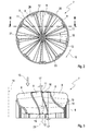
- the respective device 7 has a plurality of blades 8, which are distributed in the circumferential direction and which project inwardly from an outer wall 9 of the device 7.
- each blade has 8 in the axial section or in the axial direction a profile 10 with a leading edge 11 and a trailing edge 12.
- a prevailing during operation of the device 7 flow direction is z.
- the axial direction of the device 7 is z.
- Fig. 3 indicated by a dot-dash line and designated 14.
- the circumferential direction of the device 7 is z.
- Fig. 2 indicated by a curved double arrow 15.
- the blades 8 are profiled at least in a region adjoining the outer wall 9 such that an offset 16 exists between the leading edge 11 and the trailing edge 12 in the circumferential direction 15. This is the appropriate Blade 8 at least in this adjacent to the outer wall 9 area opposite the exhaust gas flow 13 employed.
- the profile 10 at both the leading edge 11 and at the trailing edge 12 with respect to the axial direction 14 has an angle of attack 17 which is small and in a range of -10 ° inclusive to + 10 ° inclusive.
- the angle of attack 17, the leading edge 11 and the trailing edge 12 occupy with respect to the axial direction 14, in a range of from -5 ° to + 5 ° inclusive.
- the angle of attack 17 of leading edge 11 and trailing edge 12 need not be the same. In particular, they can also have a different sign. However, an embodiment is preferred in which said angle of incidence 17 is substantially zero, so that the profile 10 is oriented at its leading edge 11 and at its trailing edge 12 substantially parallel to the axial direction 14.
- the profile 10 between leading edge 11 and trailing edge 12 has an angle of attack 18 with respect to the axial direction 14, which is greater than the prevailing at the leading edge 11 and at the trailing edge 12 Anstellwinkel 17.
- the angle of attack 18 increase between leading edge 11 and trailing edge 12 to a value of at least 30 °.
- the prevailing between leading edge 11 and trailing edge 12 angle of attack 18 of the profile 10 reaches directly on the outer wall 9 even 45 ° or about 45 °.
- the angle of incidence present between leading edge 11 and trailing edge 12 increases starting from the value prevailing at leading edge 11 up to its maximum and subsequently drops to the value prevailing at trailing edge 12.
- the profile 10 is shaped so that it is ungrounded from the leading edge 11 to the trailing edge 12 and in particular has a steady course.
- the respective profile 10 between its leading edge 11 and its trailing edge 12 has only a single point of inflection, in Fig. 3 designated 19.
- the inflection point 19 lies on an imaginary center line of the profile 10, which is located centrally between the inflow side and the outflow side of the profile 10.
- the inflection point 19 is preferably arranged centrally between leading edge 11 and trailing edge 12, so that the change in the setting angle 18 along the profile 10 in particular can increase and decrease symmetrically.
- the geometry of the blades 8 or the shaping of the profile 10 can also have a straight-line section 32, which is located between the leading edge 11 and the trailing edge 12, in particular centrally, according to FIG Fig. 4 at least directly on the outer wall 9.
- the profiling and shaping of the blades 8 also takes place such that the offset 16 present in the circumferential direction between leading edge 11 and trailing edge 12 decreases along the respective blade 8 from outside to inside. This is achieved by a twist of the respective blade 8 with respect to its radial extent.
- the twisting of the blades 8 is realized in the particular embodiments shown here so that the angle of attack 17 of the profile 10 at the leading edge 11 and at the trailing edge 12 along the respective blade 8 from outside to inside is constant. The angle of attack 17 occurring at the leading edge 11 and at the trailing edge 12 is thus the same over the entire radial extent of the blades 8.
- the angle of attack 18 prevailing between the leading edge 11 and the trailing edge 12 varies along the radial extent of the blades 8.
- Said angle of incidence 18 prevailing between the leading edge 11 and the trailing edge 12 increases along the respective blade 8 from outside to inside.
- the largest angle of attack 18 of the profile 10 prevails.
- the smallest angle of attack 18 occurs at a radially inner end of the respective blade 8 between leading edge 11 and trailing edge 12 in each case the smallest angle of attack 18, which leads to the smallest offset 16.
- the respective blade 8 has a straight end edge 20 at its end which is distal to the outer wall 9, that is to say at its inner end.
- the respective end edge 20 extends parallel to the axial direction 14.
- the inner end edges 20 of the blades 8 can be positioned very close to each other. In particular, it is possible to position the inner ends free-standing, so that the blades 8 do not touch at their inner ends.
- the blades touch 8 at their inner ends and in particular support each other.
- the blades 8 can be supported at their inner ends under bias to each other, whereby a targeted stiffening of the device 7 can be realized in the mounted state.
- the shaping of the blades 8 expediently also takes place in such a way that the leading edges 11 extend straight from the outside to the inside along the respective blade 8, ie along straight lines. Additionally or alternatively may also the trailing edges 12 along the respective blade 8 from outside to inside straight, so extend along straight lines.
- these straight leading edges 11 and the straight trailing edges 12 are exactly radially oriented, so that they extend radially in a star-shaped manner from a longitudinal central axis 21 of the device 7.
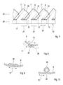
- the Fig. 2-6 show an embodiment of the device 7, in which the device 7 is made of a single sheet metal part 22 by forming, which in Fig. 7 is reproduced.
- Corresponding Fig. 7 extends in the reproduced here production state in which the sheet metal part 22 is unwound or unrolled in the plane and in a longitudinal direction 23.
- the sheet metal part 22 is designed strip-shaped, so that it also referred to as sheet metal strip 22nd can be designated.
- the blades 8 are cut or punched out. Visible are the leading edges 11, the trailing edges 12 and the straight inner end edges 20.
- the, z. Tie Fig. 2-6 recognizable, rounded transitions from the radial state in the mounted state edges, z. B. 11 and 12, to the axial in the mounted state edges, z. B. 20, not shown.
- the other (lower) longitudinal side 25 connects the individual blades 8 with each other and forms in the finished state of the device 7, the outer wall 9.
- the sheet metal strip 22 is wound in its plane transverse to its longitudinal direction 23 or rolled up, so that then the longitudinal direction 23 of the sheet metal strip 22 in the circumferential direction 15 of the outer wall 9 extends.
- the metal strip 22 and its longitudinal side 25 to perform the outer wall 9 so that the outer wall 9 associated longitudinal side 25 in the in Fig. 7 shown, not formed state is longer than the circumference of the outer wall made therefrom.
- the deformation of the metal strip 22 can be carried out so that the outer wall 9 with several, in the Fig. 2-6 recognizable Einschlingept 26 is arranged, which are arranged distributed in the circumferential direction 15. These inclinations 26 are from the in Fig. 7 formed by curly braces areas 27 of the longitudinal side 25, which is associated with the outer wall 9.
- the inclusions 26 project inwards from the outer wall 9. They are designed flat or flat fitting. In the in the Fig. 2-6 In the embodiments shown, the inclusions 26 are symmetrically shaped with respect to the circumferential direction 15.
- Fig. 8 shows a loop 26 of another embodiment in which the Einschlingungen 26 protrude from the outer wall 9 to the outside.
- the inclusions 26 in the installed state of the device 7, the outer wall 9 at an in Fig. 8 Supported by broken lines indicated inner wall 28 of the exhaust gas line 4 of the exhaust system 3. They can be shaped so that on the one hand they realize a resilient support in the radial direction and / or on the other hand enable prestressed positioning and thus also fixation of the device 7 in the conduit 4 axially.
- FIG. 9 shows an embodiment in which the Einschlingungen 26 are formed asymmetrically with respect to the circumferential direction 15 and thus in particular allow complete placement in the flow shadow of one of the blades 8. Also at the in Fig. 9 In the embodiment shown, the inclusions 26 are flat and also designed to project inward.
- Fig. 10 shows a further variant for the realization of the Einschlingungen 26.
- the shown loop 26 is inwardly from the outer wall 9 from.
- the inclusions 26 are shaped so that the outer wall 9 in the region of the respective loop 26 has a gap 29, whereby in the circumferential direction 15 a spring action with the help of the respective loop 26 can be realized, for example, to manufacturing tolerances and / or to compensate for thermal expansion effects in the circumferential direction 15.
- FIGS. 11 and 12 another embodiment in which the device 7 is not integrally formed from a single sheet metal part 22, but in which the device 7 is built.
- the device 7 has a plurality of blade parts 30, which each have at least one blade 8.
- an annular body 31 is provided which forms the outer wall 9.
- the blade parts 30 are attached to the ring body 31 so as to construct the device 7.
- the annular body 31 may be interrupted or slotted in the circumferential direction 15 at least at one point, for. B. to match manufacturing tolerances and / or thermal rotation effects in the circumferential direction 15.
- the respective blade part 30 may also comprise two or more blades 8.
- the in the FIGS. 11 and 12 shown variant of the device 7 comes without inclusions 26, which protrude from the outer wall 9 inwardly or outwardly.
Landscapes
- Chemical & Material Sciences (AREA)
- Chemical Kinetics & Catalysis (AREA)
- Engineering & Computer Science (AREA)
- Health & Medical Sciences (AREA)
- Toxicology (AREA)
- Combustion & Propulsion (AREA)
- Mechanical Engineering (AREA)
- General Engineering & Computer Science (AREA)
- Dispersion Chemistry (AREA)
- Exhaust Gas After Treatment (AREA)
Applications Claiming Priority (1)
| Application Number | Priority Date | Filing Date | Title |
|---|---|---|---|
| DE102009034670A DE102009034670A1 (de) | 2009-07-25 | 2009-07-25 | Misch- und/oder Verdampfungseinrichtung |
Publications (3)
| Publication Number | Publication Date |
|---|---|
| EP2278133A2 true EP2278133A2 (fr) | 2011-01-26 |
| EP2278133A3 EP2278133A3 (fr) | 2012-08-08 |
| EP2278133B1 EP2278133B1 (fr) | 2014-12-31 |
Family
ID=43031486
Family Applications (1)
| Application Number | Title | Priority Date | Filing Date |
|---|---|---|---|
| EP10167377.0A Not-in-force EP2278133B1 (fr) | 2009-07-25 | 2010-06-25 | Dispositif de mélange et/ou d'évaporation |
Country Status (4)
| Country | Link |
|---|---|
| US (1) | US8511076B2 (fr) |
| EP (1) | EP2278133B1 (fr) |
| CN (1) | CN101968003B (fr) |
| DE (1) | DE102009034670A1 (fr) |
Cited By (3)
| Publication number | Priority date | Publication date | Assignee | Title |
|---|---|---|---|---|
| EP2535535A1 (fr) * | 2011-06-16 | 2012-12-19 | Bosch Emission Systems GmbH & Co. KG | Mélangeur statique |
| US9790833B2 (en) | 2014-07-31 | 2017-10-17 | Eberspächer Exhaust Technology GmbH & Co. KG | Mixer and mixing device for an exhaust system |
| EP3293378A1 (fr) * | 2016-09-13 | 2018-03-14 | Eberspächer North America Inc. | Mélangeur pour un système d'échappement |
Families Citing this family (22)
| Publication number | Priority date | Publication date | Assignee | Title |
|---|---|---|---|---|
| US6656211B1 (en) | 2000-10-26 | 2003-12-02 | Scimed Life Systems, Inc. | Stent delivery system with improved tracking |
| DE102010014037A1 (de) | 2009-04-02 | 2010-11-04 | Cummins Filtration IP, Inc., Minneapolis | Reduktionsmittelzersetzungssystem |
| US20120204541A1 (en) * | 2011-02-14 | 2012-08-16 | GM Global Technology Operations LLC | Exhaust mixer element and method for mixing |
| US8747758B2 (en) | 2011-12-12 | 2014-06-10 | Uop Llc | Process and apparatus for mixing two streams of catalyst |
| US8747759B2 (en) | 2011-12-12 | 2014-06-10 | Uop Llc | Process and apparatus for mixing two streams of catalyst |
| US8747657B2 (en) | 2011-12-12 | 2014-06-10 | Uop Llc | Process and apparatus for mixing two streams of catalyst |
| US8815082B2 (en) | 2011-12-12 | 2014-08-26 | Uop Llc | Process and apparatus for mixing two streams of catalyst |
| US8936758B2 (en) | 2012-03-20 | 2015-01-20 | Uop Llc | Process and apparatus for mixing two streams of catalyst |
| US9375695B2 (en) | 2012-03-20 | 2016-06-28 | Uop Llc | Process and apparatus for mixing two streams of catalyst |
| US8916099B2 (en) | 2012-03-20 | 2014-12-23 | Uop Llc | Process and apparatus for mixing two streams of catalyst |
| US8815166B2 (en) | 2012-03-20 | 2014-08-26 | Uop Llc | Process and apparatus for mixing two streams of catalyst |
| JP6125248B2 (ja) * | 2013-01-31 | 2017-05-10 | 日野自動車株式会社 | 尿素水ミキシング構造 |
| JP6108461B2 (ja) * | 2013-10-09 | 2017-04-05 | ヤンマー株式会社 | 排気浄化装置 |
| US9205394B2 (en) | 2014-03-31 | 2015-12-08 | Uop Llc | Process and apparatus for distributing fluidizing gas to an FCC riser |
| US9376633B2 (en) | 2014-03-31 | 2016-06-28 | Uop Llc | Process and apparatus for distributing fluidizing gas to an FCC riser |
| BR112017026777B1 (pt) | 2015-06-12 | 2022-11-16 | Donaldson Company, Inc | Dispositivo de tratamento de escape |
| US10113468B2 (en) * | 2015-07-17 | 2018-10-30 | Middleville Tool & Die Co. | Mixer assembly for exhaust systems and method of forming the same |
| DE112017000713A5 (de) * | 2016-02-09 | 2018-10-31 | FEV Europe GmbH | Mischer zum durchmischen eines abgasstroms einer brennkraftmaschine und abgasanlage |
| DE102019100267A1 (de) * | 2019-01-08 | 2020-07-09 | Eberspächer Exhaust Technology GmbH & Co. KG | Mischer für eine Abgasanlage einer Brennkraftmaschine |
| EP3997314B1 (fr) | 2019-07-11 | 2024-03-06 | Donaldson Company, Inc. | Arrangement d'un conduit de dosage pour un système de post-traitement des gaz d'échappement |
| EP3792462A1 (fr) | 2019-09-13 | 2021-03-17 | Donaldson Company, Inc. | Ensembles de dosage et de mélange pour système de post-traitement d'échappement |
| CN112933866B (zh) * | 2021-03-22 | 2022-07-22 | 哈尔滨工程大学 | 一种可用于有害气体净化处理的气液两相引射器 |
Citations (1)
| Publication number | Priority date | Publication date | Assignee | Title |
|---|---|---|---|---|
| DE102007028449A1 (de) | 2007-04-25 | 2008-10-30 | J. Eberspächer GmbH & Co. KG | Misch- und/oder Verdampfungseinrichtung und zugehöriges Herstellungsverfahren |
Family Cites Families (15)
| Publication number | Priority date | Publication date | Assignee | Title |
|---|---|---|---|---|
| US4041113A (en) * | 1973-05-30 | 1977-08-09 | Mass Transfer Limited | Tower packing elements |
| DE3536315A1 (de) * | 1985-10-11 | 1987-04-16 | Sueddeutsche Kuehler Behr | Katalysatoranordnung zur reinigung von abgasen, insbesondere einer brennkraftmaschine |
| US5355973A (en) * | 1992-06-02 | 1994-10-18 | Donaldson Company, Inc. | Muffler with catalytic converter arrangement; and method |
| WO1997035107A1 (fr) * | 1996-03-18 | 1997-09-25 | Cheng Theodore Yi Tze | Dispositif produisant un ecoulement tourbillonnaire d'essence pour moteur a combustion interne |
| US6449947B1 (en) * | 2001-10-17 | 2002-09-17 | Fleetguard, Inc. | Low pressure injection and turbulent mixing in selective catalytic reduction system |
| DE10239417B4 (de) * | 2002-08-28 | 2009-09-24 | J. Eberspächer GmbH & Co. KG | Heißgas-Strömungskanal, insbesondere innerhalb einer Abgasanlage eines Verbrennungsmotors stromauf eines Katalysators |
| US6837213B1 (en) * | 2003-12-15 | 2005-01-04 | David T. Burnett | Power booster fuel saver |
| US7028663B1 (en) * | 2005-01-26 | 2006-04-18 | Kim Jay S | Fluid swirling device |
| US7805932B2 (en) * | 2006-09-29 | 2010-10-05 | Perkins Engines Company Limited | Flow assembly for an exhaust system |
| DE102007012790B4 (de) * | 2007-03-16 | 2009-07-23 | Audi Ag | Statischer Mischer für eine Abgasanlage einer Brennkraftmaschine |
| EP1982756A1 (fr) * | 2007-04-19 | 2008-10-22 | Magneti Marelli Sistemi di Scarico S.p.a. | Système d'échappement d'un moteur à combustion interne |
| DE102007019878A1 (de) * | 2007-04-25 | 2008-11-06 | J. Eberspächer GmbH & Co. KG | Misch- und/oder Verdampfungseinrichtung und zugehöriges Herstellungsverfahren |
| FR2921415B1 (fr) * | 2007-09-25 | 2010-12-31 | Faurecia Sys Echappement | Melangeur destine a etre dispose a l'interieur d'un element d'une ligne d'echappement d'un vehicule automobile |
| DE102008023585A1 (de) * | 2008-05-14 | 2009-01-22 | Daimler Ag | Abgasstrang und Verfahren zum Zuführen von Abgas einer Verbrennungskraftmaschine zu einer Abgasnachbehandlungseinrichtung |
| US8397495B2 (en) * | 2008-06-26 | 2013-03-19 | Tenneco Automotive Operating Company Inc. | Exhaust gas additive/treatment system and mixer for use therein |
-
2009
- 2009-07-25 DE DE102009034670A patent/DE102009034670A1/de not_active Withdrawn
-
2010
- 2010-06-25 EP EP10167377.0A patent/EP2278133B1/fr not_active Not-in-force
- 2010-06-28 US US12/824,496 patent/US8511076B2/en active Active
- 2010-07-26 CN CN201010236444.7A patent/CN101968003B/zh not_active Expired - Fee Related
Patent Citations (1)
| Publication number | Priority date | Publication date | Assignee | Title |
|---|---|---|---|---|
| DE102007028449A1 (de) | 2007-04-25 | 2008-10-30 | J. Eberspächer GmbH & Co. KG | Misch- und/oder Verdampfungseinrichtung und zugehöriges Herstellungsverfahren |
Cited By (5)
| Publication number | Priority date | Publication date | Assignee | Title |
|---|---|---|---|---|
| EP2535535A1 (fr) * | 2011-06-16 | 2012-12-19 | Bosch Emission Systems GmbH & Co. KG | Mélangeur statique |
| US10500550B2 (en) | 2011-06-16 | 2019-12-10 | Robert Bosch Gmbh | Static mixer |
| US9790833B2 (en) | 2014-07-31 | 2017-10-17 | Eberspächer Exhaust Technology GmbH & Co. KG | Mixer and mixing device for an exhaust system |
| EP3293378A1 (fr) * | 2016-09-13 | 2018-03-14 | Eberspächer North America Inc. | Mélangeur pour un système d'échappement |
| US10539059B2 (en) | 2016-09-13 | 2020-01-21 | Eberspächer North America Inc. | Mixer for an exhaust system |
Also Published As
| Publication number | Publication date |
|---|---|
| CN101968003A (zh) | 2011-02-09 |
| CN101968003B (zh) | 2014-12-10 |
| US8511076B2 (en) | 2013-08-20 |
| DE102009034670A1 (de) | 2011-01-27 |
| EP2278133B1 (fr) | 2014-12-31 |
| US20110016856A1 (en) | 2011-01-27 |
| EP2278133A3 (fr) | 2012-08-08 |
Similar Documents
| Publication | Publication Date | Title |
|---|---|---|
| EP2278133B1 (fr) | Dispositif de mélange et/ou d'évaporation | |
| EP2006017B1 (fr) | Dispositif de mélange et/ou d'évaporation et procédé de fabrication correspondant | |
| EP1985356B1 (fr) | Dispositif de mélange et/ou d'évaporation | |
| DE102013204189B4 (de) | Mischsystem | |
| DE102008018461B4 (de) | Mischvorrichtung für eine Abgasnachbehandlungsanlage | |
| EP1953359B1 (fr) | Dispositif d'échappement d'un moteur à combustion interne | |
| EP1830042B1 (fr) | Mélangeur statique et dispositif de traitement de gaz d'échappement | |
| EP2535535B1 (fr) | Mélangeur statique | |
| EP2700442B1 (fr) | Installation de gaz d'échappement avec dispositif de mélange et/ou d'évaporation | |
| EP2101049B1 (fr) | Système de post-traitement de gaz d'échappement compact | |
| EP2022956B1 (fr) | Système d'échappement avec dispositif de guidage de l'écoulement | |
| DE102004020138B4 (de) | Reduktionsmittelzugabesystem | |
| EP2921220B1 (fr) | Mélangeur pour une installation de gaz d'échappement | |
| EP2388063B1 (fr) | Système d'échappement comprenant un mélangeur statique | |
| DE102008029110A1 (de) | Misch- und/oder Verdampfungseinrichtung | |
| EP2027372B1 (fr) | Filtre à flux secondaire avec rendement de filtre amélioré | |
| EP2574750B1 (fr) | Dispositif de mélange et/ou d'évaporation | |
| DE102008017395C5 (de) | Misch- und/oder Verdampfungseinrichtung | |
| EP2974787A2 (fr) | Melangeur statique | |
| EP2594330A1 (fr) | Dispositif de mélange et/ou dýévaporation | |
| DE112023000562T5 (de) | Ultra-kompaktes nachbehandlungssystem, kompressoranordnung und motor | |
| DE102012014528A1 (de) | Mehrstufiger Plattenmischer | |
| DE102008053106B4 (de) | Misch- und/oder Verdampfungseinrichtung und zugehöriges Herstellungsverfahren | |
| DE202021103290U1 (de) | Zylindrisches Gehäuse, Wärmeisolierabdeckung, Abgassystem, Verbindungselement und Werkzeugausrüstung | |
| EP2823878B1 (fr) | Mélangeur à plaques à plusieurs étages |
Legal Events
| Date | Code | Title | Description |
|---|---|---|---|
| PUAI | Public reference made under article 153(3) epc to a published international application that has entered the european phase |
Free format text: ORIGINAL CODE: 0009012 |
|
| AK | Designated contracting states |
Kind code of ref document: A2 Designated state(s): AL AT BE BG CH CY CZ DE DK EE ES FI FR GB GR HR HU IE IS IT LI LT LU LV MC MK MT NL NO PL PT RO SE SI SK SM TR |
|
| AX | Request for extension of the european patent |
Extension state: BA ME RS |
|
| RIC1 | Information provided on ipc code assigned before grant |
Ipc: F01N 3/28 20060101ALI20120313BHEP Ipc: B01F 3/04 20060101ALI20120313BHEP Ipc: B01F 5/06 20060101ALI20120313BHEP Ipc: B21D 53/00 20060101ALI20120313BHEP Ipc: F01N 3/20 20060101AFI20120313BHEP Ipc: B01F 5/04 20060101ALI20120313BHEP |
|
| PUAL | Search report despatched |
Free format text: ORIGINAL CODE: 0009013 |
|
| AK | Designated contracting states |
Kind code of ref document: A3 Designated state(s): AL AT BE BG CH CY CZ DE DK EE ES FI FR GB GR HR HU IE IS IT LI LT LU LV MC MK MT NL NO PL PT RO SE SI SK SM TR |
|
| AX | Request for extension of the european patent |
Extension state: BA ME RS |
|
| RIC1 | Information provided on ipc code assigned before grant |
Ipc: B01F 5/04 20060101ALI20120629BHEP Ipc: F01N 3/28 20060101ALI20120629BHEP Ipc: B01F 3/04 20060101ALI20120629BHEP Ipc: B01F 5/06 20060101ALI20120629BHEP Ipc: B21D 53/00 20060101ALI20120629BHEP Ipc: F01N 3/20 20060101AFI20120629BHEP |
|
| 17P | Request for examination filed |
Effective date: 20130208 |
|
| RAP1 | Party data changed (applicant data changed or rights of an application transferred) |
Owner name: EBERSPAECHER EXHAUST TECHNOLOGY GMBH & CO. KG |
|
| 17Q | First examination report despatched |
Effective date: 20130701 |
|
| GRAP | Despatch of communication of intention to grant a patent |
Free format text: ORIGINAL CODE: EPIDOSNIGR1 |
|
| INTG | Intention to grant announced |
Effective date: 20141001 |
|
| GRAS | Grant fee paid |
Free format text: ORIGINAL CODE: EPIDOSNIGR3 |
|
| GRAA | (expected) grant |
Free format text: ORIGINAL CODE: 0009210 |
|
| AK | Designated contracting states |
Kind code of ref document: B1 Designated state(s): AL AT BE BG CH CY CZ DE DK EE ES FI FR GB GR HR HU IE IS IT LI LT LU LV MC MK MT NL NO PL PT RO SE SI SK SM TR |
|
| REG | Reference to a national code |
Ref country code: CH Ref legal event code: EP Ref country code: GB Ref legal event code: FG4D Free format text: NOT ENGLISH |
|
| REG | Reference to a national code |
Ref country code: IE Ref legal event code: FG4D Free format text: LANGUAGE OF EP DOCUMENT: GERMAN |
|
| REG | Reference to a national code |
Ref country code: AT Ref legal event code: REF Ref document number: 704552 Country of ref document: AT Kind code of ref document: T Effective date: 20150215 |
|
| REG | Reference to a national code |
Ref country code: DE Ref legal event code: R096 Ref document number: 502010008602 Country of ref document: DE Effective date: 20150219 |
|
| PG25 | Lapsed in a contracting state [announced via postgrant information from national office to epo] |
Ref country code: NO Free format text: LAPSE BECAUSE OF FAILURE TO SUBMIT A TRANSLATION OF THE DESCRIPTION OR TO PAY THE FEE WITHIN THE PRESCRIBED TIME-LIMIT Effective date: 20150331 Ref country code: LT Free format text: LAPSE BECAUSE OF FAILURE TO SUBMIT A TRANSLATION OF THE DESCRIPTION OR TO PAY THE FEE WITHIN THE PRESCRIBED TIME-LIMIT Effective date: 20141231 Ref country code: FI Free format text: LAPSE BECAUSE OF FAILURE TO SUBMIT A TRANSLATION OF THE DESCRIPTION OR TO PAY THE FEE WITHIN THE PRESCRIBED TIME-LIMIT Effective date: 20141231 |
|
| REG | Reference to a national code |
Ref country code: NL Ref legal event code: VDEP Effective date: 20141231 |
|
| REG | Reference to a national code |
Ref country code: LT Ref legal event code: MG4D |
|
| PG25 | Lapsed in a contracting state [announced via postgrant information from national office to epo] |
Ref country code: HR Free format text: LAPSE BECAUSE OF FAILURE TO SUBMIT A TRANSLATION OF THE DESCRIPTION OR TO PAY THE FEE WITHIN THE PRESCRIBED TIME-LIMIT Effective date: 20141231 Ref country code: SE Free format text: LAPSE BECAUSE OF FAILURE TO SUBMIT A TRANSLATION OF THE DESCRIPTION OR TO PAY THE FEE WITHIN THE PRESCRIBED TIME-LIMIT Effective date: 20141231 Ref country code: LV Free format text: LAPSE BECAUSE OF FAILURE TO SUBMIT A TRANSLATION OF THE DESCRIPTION OR TO PAY THE FEE WITHIN THE PRESCRIBED TIME-LIMIT Effective date: 20141231 Ref country code: GR Free format text: LAPSE BECAUSE OF FAILURE TO SUBMIT A TRANSLATION OF THE DESCRIPTION OR TO PAY THE FEE WITHIN THE PRESCRIBED TIME-LIMIT Effective date: 20150401 |
|
| PG25 | Lapsed in a contracting state [announced via postgrant information from national office to epo] |
Ref country code: NL Free format text: LAPSE BECAUSE OF FAILURE TO SUBMIT A TRANSLATION OF THE DESCRIPTION OR TO PAY THE FEE WITHIN THE PRESCRIBED TIME-LIMIT Effective date: 20141231 |
|
| PG25 | Lapsed in a contracting state [announced via postgrant information from national office to epo] |
Ref country code: SK Free format text: LAPSE BECAUSE OF FAILURE TO SUBMIT A TRANSLATION OF THE DESCRIPTION OR TO PAY THE FEE WITHIN THE PRESCRIBED TIME-LIMIT Effective date: 20141231 Ref country code: RO Free format text: LAPSE BECAUSE OF FAILURE TO SUBMIT A TRANSLATION OF THE DESCRIPTION OR TO PAY THE FEE WITHIN THE PRESCRIBED TIME-LIMIT Effective date: 20141231 Ref country code: ES Free format text: LAPSE BECAUSE OF FAILURE TO SUBMIT A TRANSLATION OF THE DESCRIPTION OR TO PAY THE FEE WITHIN THE PRESCRIBED TIME-LIMIT Effective date: 20141231 Ref country code: CZ Free format text: LAPSE BECAUSE OF FAILURE TO SUBMIT A TRANSLATION OF THE DESCRIPTION OR TO PAY THE FEE WITHIN THE PRESCRIBED TIME-LIMIT Effective date: 20141231 |
|
| PG25 | Lapsed in a contracting state [announced via postgrant information from national office to epo] |
Ref country code: IS Free format text: LAPSE BECAUSE OF FAILURE TO SUBMIT A TRANSLATION OF THE DESCRIPTION OR TO PAY THE FEE WITHIN THE PRESCRIBED TIME-LIMIT Effective date: 20150430 Ref country code: PL Free format text: LAPSE BECAUSE OF FAILURE TO SUBMIT A TRANSLATION OF THE DESCRIPTION OR TO PAY THE FEE WITHIN THE PRESCRIBED TIME-LIMIT Effective date: 20141231 |
|
| REG | Reference to a national code |
Ref country code: DE Ref legal event code: R097 Ref document number: 502010008602 Country of ref document: DE |
|
| PG25 | Lapsed in a contracting state [announced via postgrant information from national office to epo] |
Ref country code: EE Free format text: LAPSE BECAUSE OF FAILURE TO SUBMIT A TRANSLATION OF THE DESCRIPTION OR TO PAY THE FEE WITHIN THE PRESCRIBED TIME-LIMIT Effective date: 20141231 Ref country code: DK Free format text: LAPSE BECAUSE OF FAILURE TO SUBMIT A TRANSLATION OF THE DESCRIPTION OR TO PAY THE FEE WITHIN THE PRESCRIBED TIME-LIMIT Effective date: 20141231 |
|
| PLBE | No opposition filed within time limit |
Free format text: ORIGINAL CODE: 0009261 |
|
| STAA | Information on the status of an ep patent application or granted ep patent |
Free format text: STATUS: NO OPPOSITION FILED WITHIN TIME LIMIT |
|
| 26N | No opposition filed |
Effective date: 20151001 |
|
| PG25 | Lapsed in a contracting state [announced via postgrant information from national office to epo] |
Ref country code: MC Free format text: LAPSE BECAUSE OF FAILURE TO SUBMIT A TRANSLATION OF THE DESCRIPTION OR TO PAY THE FEE WITHIN THE PRESCRIBED TIME-LIMIT Effective date: 20141231 |
|
| REG | Reference to a national code |
Ref country code: CH Ref legal event code: PL |
|
| GBPC | Gb: european patent ceased through non-payment of renewal fee |
Effective date: 20150625 |
|
| PG25 | Lapsed in a contracting state [announced via postgrant information from national office to epo] |
Ref country code: LU Free format text: LAPSE BECAUSE OF FAILURE TO SUBMIT A TRANSLATION OF THE DESCRIPTION OR TO PAY THE FEE WITHIN THE PRESCRIBED TIME-LIMIT Effective date: 20150625 Ref country code: SI Free format text: LAPSE BECAUSE OF FAILURE TO SUBMIT A TRANSLATION OF THE DESCRIPTION OR TO PAY THE FEE WITHIN THE PRESCRIBED TIME-LIMIT Effective date: 20141231 |
|
| REG | Reference to a national code |
Ref country code: IE Ref legal event code: MM4A |
|
| PG25 | Lapsed in a contracting state [announced via postgrant information from national office to epo] |
Ref country code: IE Free format text: LAPSE BECAUSE OF NON-PAYMENT OF DUE FEES Effective date: 20150625 Ref country code: GB Free format text: LAPSE BECAUSE OF NON-PAYMENT OF DUE FEES Effective date: 20150625 Ref country code: CH Free format text: LAPSE BECAUSE OF NON-PAYMENT OF DUE FEES Effective date: 20150630 Ref country code: LI Free format text: LAPSE BECAUSE OF NON-PAYMENT OF DUE FEES Effective date: 20150630 |
|
| REG | Reference to a national code |
Ref country code: FR Ref legal event code: PLFP Year of fee payment: 7 |
|
| REG | Reference to a national code |
Ref country code: AT Ref legal event code: MM01 Ref document number: 704552 Country of ref document: AT Kind code of ref document: T Effective date: 20150625 |
|
| PG25 | Lapsed in a contracting state [announced via postgrant information from national office to epo] |
Ref country code: AT Free format text: LAPSE BECAUSE OF NON-PAYMENT OF DUE FEES Effective date: 20150625 |
|
| PG25 | Lapsed in a contracting state [announced via postgrant information from national office to epo] |
Ref country code: MT Free format text: LAPSE BECAUSE OF FAILURE TO SUBMIT A TRANSLATION OF THE DESCRIPTION OR TO PAY THE FEE WITHIN THE PRESCRIBED TIME-LIMIT Effective date: 20141231 |
|
| PG25 | Lapsed in a contracting state [announced via postgrant information from national office to epo] |
Ref country code: HU Free format text: LAPSE BECAUSE OF FAILURE TO SUBMIT A TRANSLATION OF THE DESCRIPTION OR TO PAY THE FEE WITHIN THE PRESCRIBED TIME-LIMIT; INVALID AB INITIO Effective date: 20100625 Ref country code: BG Free format text: LAPSE BECAUSE OF FAILURE TO SUBMIT A TRANSLATION OF THE DESCRIPTION OR TO PAY THE FEE WITHIN THE PRESCRIBED TIME-LIMIT Effective date: 20141231 Ref country code: SM Free format text: LAPSE BECAUSE OF FAILURE TO SUBMIT A TRANSLATION OF THE DESCRIPTION OR TO PAY THE FEE WITHIN THE PRESCRIBED TIME-LIMIT Effective date: 20141231 |
|
| REG | Reference to a national code |
Ref country code: FR Ref legal event code: PLFP Year of fee payment: 8 |
|
| PG25 | Lapsed in a contracting state [announced via postgrant information from national office to epo] |
Ref country code: CY Free format text: LAPSE BECAUSE OF FAILURE TO SUBMIT A TRANSLATION OF THE DESCRIPTION OR TO PAY THE FEE WITHIN THE PRESCRIBED TIME-LIMIT Effective date: 20141231 |
|
| PG25 | Lapsed in a contracting state [announced via postgrant information from national office to epo] |
Ref country code: BE Free format text: LAPSE BECAUSE OF NON-PAYMENT OF DUE FEES Effective date: 20150630 |
|
| PG25 | Lapsed in a contracting state [announced via postgrant information from national office to epo] |
Ref country code: TR Free format text: LAPSE BECAUSE OF FAILURE TO SUBMIT A TRANSLATION OF THE DESCRIPTION OR TO PAY THE FEE WITHIN THE PRESCRIBED TIME-LIMIT Effective date: 20141231 |
|
| REG | Reference to a national code |
Ref country code: FR Ref legal event code: PLFP Year of fee payment: 9 |
|
| PG25 | Lapsed in a contracting state [announced via postgrant information from national office to epo] |
Ref country code: MK Free format text: LAPSE BECAUSE OF FAILURE TO SUBMIT A TRANSLATION OF THE DESCRIPTION OR TO PAY THE FEE WITHIN THE PRESCRIBED TIME-LIMIT Effective date: 20141231 |
|
| PG25 | Lapsed in a contracting state [announced via postgrant information from national office to epo] |
Ref country code: PT Free format text: LAPSE BECAUSE OF FAILURE TO SUBMIT A TRANSLATION OF THE DESCRIPTION OR TO PAY THE FEE WITHIN THE PRESCRIBED TIME-LIMIT Effective date: 20141231 |
|
| PG25 | Lapsed in a contracting state [announced via postgrant information from national office to epo] |
Ref country code: AL Free format text: LAPSE BECAUSE OF FAILURE TO SUBMIT A TRANSLATION OF THE DESCRIPTION OR TO PAY THE FEE WITHIN THE PRESCRIBED TIME-LIMIT Effective date: 20141231 |
|
| PGFP | Annual fee paid to national office [announced via postgrant information from national office to epo] |
Ref country code: IT Payment date: 20180622 Year of fee payment: 9 |
|
| PG25 | Lapsed in a contracting state [announced via postgrant information from national office to epo] |
Ref country code: IT Free format text: LAPSE BECAUSE OF NON-PAYMENT OF DUE FEES Effective date: 20190625 |
|
| REG | Reference to a national code |
Ref country code: DE Ref legal event code: R081 Ref document number: 502010008602 Country of ref document: DE Owner name: PUREM GMBH, DE Free format text: FORMER OWNER: EBERSPAECHER EXHAUST TECHNOLOGY GMBH & CO. KG, 66539 NEUNKIRCHEN, DE |
|
| PGFP | Annual fee paid to national office [announced via postgrant information from national office to epo] |
Ref country code: DE Payment date: 20240617 Year of fee payment: 15 |
|
| PGFP | Annual fee paid to national office [announced via postgrant information from national office to epo] |
Ref country code: FR Payment date: 20240617 Year of fee payment: 15 |
|
| REG | Reference to a national code |
Ref country code: DE Ref legal event code: R119 Ref document number: 502010008602 Country of ref document: DE |
|
| PG25 | Lapsed in a contracting state [announced via postgrant information from national office to epo] |
Ref country code: DE Free format text: LAPSE BECAUSE OF NON-PAYMENT OF DUE FEES Effective date: 20260101 |
|
| PG25 | Lapsed in a contracting state [announced via postgrant information from national office to epo] |
Ref country code: FR Free format text: LAPSE BECAUSE OF NON-PAYMENT OF DUE FEES Effective date: 20250630 |