EP2278268A2 - Appareil de mesure de déplacement optique - Google Patents
Appareil de mesure de déplacement optique Download PDFInfo
- Publication number
- EP2278268A2 EP2278268A2 EP10169462A EP10169462A EP2278268A2 EP 2278268 A2 EP2278268 A2 EP 2278268A2 EP 10169462 A EP10169462 A EP 10169462A EP 10169462 A EP10169462 A EP 10169462A EP 2278268 A2 EP2278268 A2 EP 2278268A2
- Authority
- EP
- European Patent Office
- Prior art keywords
- light
- wavelength
- displacement meter
- polarized
- polarized light
- Prior art date
- Legal status (The legal status is an assumption and is not a legal conclusion. Google has not performed a legal analysis and makes no representation as to the accuracy of the status listed.)
- Granted
Links
Images


Classifications
-
- G—PHYSICS
- G01—MEASURING; TESTING
- G01B—MEASURING LENGTH, THICKNESS OR SIMILAR LINEAR DIMENSIONS; MEASURING ANGLES; MEASURING AREAS; MEASURING IRREGULARITIES OF SURFACES OR CONTOURS
- G01B11/00—Measuring arrangements characterised by the use of optical techniques
- G01B11/02—Measuring arrangements characterised by the use of optical techniques for measuring length, width or thickness
- G01B11/026—Measuring arrangements characterised by the use of optical techniques for measuring length, width or thickness by measuring distance between sensor and object
-
- G—PHYSICS
- G01—MEASURING; TESTING
- G01B—MEASURING LENGTH, THICKNESS OR SIMILAR LINEAR DIMENSIONS; MEASURING ANGLES; MEASURING AREAS; MEASURING IRREGULARITIES OF SURFACES OR CONTOURS
- G01B11/00—Measuring arrangements characterised by the use of optical techniques
- G01B11/24—Measuring arrangements characterised by the use of optical techniques for measuring contours or curvatures
-
- G—PHYSICS
- G01—MEASURING; TESTING
- G01J—MEASUREMENT OF INTENSITY, VELOCITY, SPECTRAL CONTENT, POLARISATION, PHASE OR PULSE CHARACTERISTICS OF INFRARED, VISIBLE OR ULTRAVIOLET LIGHT; COLORIMETRY; RADIATION PYROMETRY
- G01J9/00—Measuring optical phase difference; Determining degree of coherence; Measuring optical wavelength
-
- G—PHYSICS
- G02—OPTICS
- G02B—OPTICAL ELEMENTS, SYSTEMS OR APPARATUS
- G02B21/00—Microscopes
- G02B21/0004—Microscopes specially adapted for specific applications
- G02B21/002—Scanning microscopes
- G02B21/0024—Confocal scanning microscopes (CSOMs) or confocal "macroscopes"; Accessories which are not restricted to use with CSOMs, e.g. sample holders
- G02B21/0032—Optical details of illumination, e.g. light-sources, pinholes, beam splitters, slits, fibers
-
- G—PHYSICS
- G02—OPTICS
- G02B—OPTICAL ELEMENTS, SYSTEMS OR APPARATUS
- G02B21/00—Microscopes
- G02B21/0004—Microscopes specially adapted for specific applications
- G02B21/002—Scanning microscopes
- G02B21/0024—Confocal scanning microscopes (CSOMs) or confocal "macroscopes"; Accessories which are not restricted to use with CSOMs, e.g. sample holders
- G02B21/0052—Optical details of the image generation
- G02B21/0064—Optical details of the image generation multi-spectral or wavelength-selective arrangements, e.g. wavelength fan-out, chromatic profiling
-
- G—PHYSICS
- G02—OPTICS
- G02B—OPTICAL ELEMENTS, SYSTEMS OR APPARATUS
- G02B21/00—Microscopes
- G02B21/0004—Microscopes specially adapted for specific applications
- G02B21/002—Scanning microscopes
- G02B21/0024—Confocal scanning microscopes (CSOMs) or confocal "macroscopes"; Accessories which are not restricted to use with CSOMs, e.g. sample holders
- G02B21/0052—Optical details of the image generation
- G02B21/0068—Optical details of the image generation arrangements using polarisation
-
- G—PHYSICS
- G01—MEASURING; TESTING
- G01B—MEASURING LENGTH, THICKNESS OR SIMILAR LINEAR DIMENSIONS; MEASURING ANGLES; MEASURING AREAS; MEASURING IRREGULARITIES OF SURFACES OR CONTOURS
- G01B2210/00—Aspects not specifically covered by any group under G01B, e.g. of wheel alignment, caliper-like sensors
- G01B2210/50—Using chromatic effects to achieve wavelength-dependent depth resolution
Definitions
- the present invention relates to an optical displacement meter and, more particularly, an improvement in a portion for measuring a wavelength of light under measurement that makes it possible to enhance resolving power and high speed response of a chromatic confocal displacement meter and miniaturize the chromatic confocal displacement meter.
- a chromatic confocal displacement meter (see JP-A-2008-256679 ) whose entire configuration is shown in Fig. 1 utilizes the following principle. Specifically, an objective lens 12 exhibiting great chromatic aberration along an optical axis varies in focal length according to a light wavelength (color). The objective lens comes into a focus at a close distance for blue light and a far distance for red light. A confocal point (the position of a focal point of a collimator lens 14 whose chromatic aberration is corrected) that is located opposite to a workpiece 8 under measurement with reference to the objective lens 12 is deemed to be common regardless of a color.
- a color focused on the workpiece 8 changes in a one-to-one correspondence according to the height of the workpiece 8. So long as a spatial filter, such as a pinhole, is provided at the location of the confocal point achieved when light reflected from the workpiece 8 returns and so long as the reflected light is let pass through the spatial filter, light of the color focused on the workpiece can be extracted.
- a spatial filter such as a pinhole
- a color (optical wavelength) is specified by use of a spectrometer 26, such as a diffraction grating, provided in a console 20, whereby the height (displacement) of the workpiece 8 exhibiting a one-to-one correspondence with the color can be measured.
- a spectrometer 26 such as a diffraction grating
- light of the color (green light in Fig. 2 ) focused on the workpiece 8 is selectively collected on the position of the confocal point on the end face 30A of the optical fiber.
- the light is captured into the core of the optical fiber and guided to the spectrometer 26 by way of an optical fiber coupler 24.
- light of the other colors is blocked by a circumference of core of the optical fiber end face 30A that is worked as the pin hole, to thus become unable to enter the optical fiber 30.
- the spectrometer 26 detects a wavelength of the light returned to an interior of the optical fiber 30, and an output from the spectrometer 26 is input to an electronic circuit 28, where the output is processed.
- a spectrometer portion for specifying a light wavelength (color) of the related-art chromatic confocal displacement meter uses a diffraction grating utilizing a diffracting phenomenon of light, a prism utilizing chromatic dispersion of a refractive index, and an optical element 26A that spatially separates colors from each other, to thus let the separated colors exit.
- a linear array light-receiving element 26B such as a C-MOS sensor, a CCD, and a photodiode array, receives light, detects a direction in which the light exited, and specifies a wavelength of the light.
- reference numeral 26C designates a collimator lens whose achromatic aberration for collimating light that has exited from the optical fiber 30 after having undergone reflection on the workpiece has been corrected.
- the linear array light-receiving element 26B When there is used the linear array light-receiving element 26B, such as that illustrated in Fig. 3 , three requirements must be satisfied in order to accomplish high resolving power; namely, (1) a narrow pitch between light receiving elements; (2) a large number of the light receiving elements; and (3) a superior signal-to-noise ratio of each of the light receiving elements.
- the pitch of the light receiving elements is narrow, the number of light receiving elements is large, and a superior signal-to-noise ratio is achieved.
- a serial output is produced, exhibition of a high speed response of 1 kHz or more is difficult.
- a noncontact displacement meter of a type other than the chromatic confocal displacement meter includes an electrostatic displacement meter, an optical interference displacement meter, an optical fiber displacement meter, a triangulation displacement meter, a focusing displacement meter for detecting the position of a lens achieved during focusing operation by scanning the objective lens, a confocal displacement meter, and the like.
- the electrostatic displacement meter can accomplish high speed response and high resolving power but encounters problems of producing a large measurement spot, providing a short working distance, being vulnerable to an inclination, and generating an error because the displacement meter is a nonconductor.
- the optical interference displacement meter also exhibits high speed response and high resolving power.
- the displacement meter produces drawbacks of being unable to cope with a step and perform ABS measurement, being vulnerable to an inclination, producing a large measurement spot, and being greatly influenced by surface roughness.
- the optical fiber displacement meter exhibits high speed response but encounters drawbacks of requiring calibration for each material, producing a large measurement spot, and providing a short working distance.
- the triangulation displacement meter exhibits a comparatively superior response but encounters drawbacks of being difficult to exhibit high speed response with high resolving power and being vulnerable to an inclination.
- the focusing displacement meter and the confocal displacement meter produce minute measurement spots and provide long working distances but encounter drawbacks of providing low response and a great heat drift.
- a displacement meter capable of accomplishing high speed response of 100 kHz or more while keeping high resolving power of the order of nanometers (high resolving power in terms of a signal-to-noise ratio rather than display resolving power) is only the electrostatic placement meter and the optical interference displacement meter.
- the electrostatic displacement meter and the optical interference displacement meter encounter drawbacks of providing a short working distance, being vulnerable to an inclination, and producing a large measurement spot.
- JP-B-1-15808 which is not the chromatic confocal displacement meter, is available as one technique for measuring a light wavelength.
- a light wavelength is measured as follows.
- a distance from the optical element 26A to the linear array light receiving element 26B must be increased in order to enlarge an angular difference between the directions of the light wavelengths as a positional difference.
- the method shown in Fig. 4 enables easy miniaturization of the displacement meter and is characterized in that higher speed response of signal processing can be accomplished when compared with a case where a slow response linear array light receiving element is used because a high response single photodiode is used.
- the present invention has been conceived to solve the drawbacks of the related art and meets a challenge of enabling accomplishment of high resolving power, high speed response, and miniaturization while taking advantage of merits of a chromatic confocal displacement meter; namely, resistance to an inclination, high linearity, a great working range, a minute measurement spot, and the ability to measure nonmetal.
- a phase difference (an optical path difference) commensurate with a light wavelength arises between vertical polarized light components passing through the wavelength plate formed from; e.g., a birefringent crystal.
- the phase difference is detected in place of a ratio between light quantities of the polari zed light components.
- the spectrometer produces a voltage output that shows a gentle monotonous change with reference to the change in light wavelength.
- an optical displacement meter configured to measure a position of a measurement target
- the optical displacement meter including: an objective lens; a broadband light source placed at a confocal point opposite to the measurement target with respect to the objective lens; a spatial filter placed at a position of a confocal point achieved when light reflected from the measurement target returns, the spatial filter being configured to extract light under measurement of a wavelength focused on the measurement target and specify the wavelength of the light under measurement; a polarizer configured to divide the light under measurement collimated and caused to propagate in one direct!
- a wavelength plate that allows passage of thy linearly polarized beams of the two directions to produce elliptically polarized light having a phase difference commensurate with a light wavelength
- a polarized light separation element configured to divide the elliptically polarized light into polarized light components with respect to the two directions
- a light receiving element configured to detect quantities of the respective polarized light components
- a computing circuit configured to perform computation of (A-B)/(A+B) by use of light quantity signals A and B detected by the light receiving element.
- the light receiving element may have an acceptance surface that is smaller than a sectional area of the collimated light passing through the polarized light separation element.
- the optical displacement meter may have a concentrating unit configured to concentrate the collimated light passing through the polarized light separation element.
- the concentrating unit may be a light collection system, and the light receiving element may be placed at a focal point of the light collection system to obtain sufficient light amount.
- a first embodiment of the present invention is directed toward a chromatic confocal displacement meter having an overall configuration such as that shown in Fig. 1 .
- a collimator lens 50 whose chromatic aberration for collimating light exiting from an optical fiber into parallel light is corrected;
- a polarizer 52 whose axis for dividing light under measurement collimated by the collimator lens 50 and caused to propagate in one direction (a direction Z) substantially equally into linearly polarized beams of two directions X and Y orthogonal to the propagating direction Z is arranged so as to be oriented in a direction of 45° between X and Y axes;
- a wavelength plate of the order of zero rather than a multi-order wavelength plate is used as the wavelength plate 54 and arranged such that the lead axis is aligned to the direction of the X axis and that the lag axis is aligned to the Y axis.
- a quarter wavelength plate for a light wavelength of 600 nm elliptically polarized light having a phase difference of about 120° to 60° between the X axis and the Y axis is obtained (a phase difference inverselyproportional to a light wavelength will arise if dispersion of a refractive index of the wavelength plate is ignored).
- a polarized beam splitter (PBS) can be used as the polarized light separation element 56.
- an output from the polarizer 52 is linearly polarized light oriented in the direction of 45° between the X and Y axes.
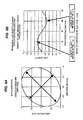
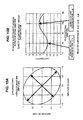
- the photodiode PDA (58A) and the photodiode PDB (58B) have received light without use of the wavelength plate, (i) a polarized state achieved at that time and (ii) a change occurred in light quantity in the direction of extraction of a polarized light component (hereinafter referred to as a "photo detecting direction”) become as illustrated in Figs. 6A and 6B .
- the output from the polarizer 52 is caused to pass through the wavelength plate (a quarter wavelength plate for use with a light wavelength of 600 nm) 54. Dispersion of a refractive index of the wavelength plate 54 caused by a light wavelength is disregarded anyway as being small.
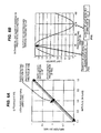
- the chromatic sensor shown in Fig. 1 uses the objective lens 12 exhibiting great chromatic aberration, light having a short wavelength, like blue light, exhibits a great refractive index, thereby making a focus at a close distance, as illustrated in Fig. 1 .
- light having a long wavelength, like red light exhibits a small refractive index, thereby making a focus at a long distance, as also illustrated in Fig. 1 .
- the characteristic is not linear.
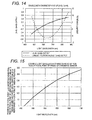
- a light wavelength characteristic acquired as a result of a change in the position of the focal point is depicted as; for instance, a curve such as that illustrated in Fig. 15 .
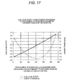
- An output characteristic (A-B) / (A+B) (an output from the spectrometer) responsive to displacement of the workpiece (the position of the focal point of the probe) finally becomes as illustrated as shown in Fig. 17 .
- An example light wavelength characteristic of a change in the position of the focal point of the chromatic sensor is one example.
- the output characteristic can be made more linearly depending on a change in lens design. It is also possible to further subject the (A-B)/(A+B) output to linearity correction by means of an analogue circuit or a digital circuit, thereby enhancing linearity.
- a second embodiment of the present invention that can improve the response speed is described in detail hereunder.
- a receiver circuit that realizes a high-speed response can be configured by using a photodiode having a little interterminal capacity (electrostatic capacity). Since an electrostatic capacity of depletion layer of p-n junction in the photodiode is proportional to an area of an acceptance surface of the photodiode, the high-speed response can be realized when the acceptance surface is made to small to make the electrostatic capacity smaller.
- the lights received by the photodiodes 58A and 58B are collimated lights as shown in Fig. 18A .
- the acceptance surface is smaller than the sectional area of the collimated light, it is necessary to make an incident beam of the acceptance surface thinner. Therefore, in the second embodiment, the collimated light is made thin as a low light spot less than dozens ⁇ m diameter by using achromatic lenses 62A and 62B as shown in Fig.18B .
- the acceptance surface of the photodiode of the first embodiment has a size of a few mm square or ⁇
- the interterminal capacity is dozens pF
- the response speed is a few hundred kHz.
- the acceptance surface of the photodiode of the second embodiment has a size fallen within a range from dozens ⁇ m square or ⁇ to a few hundred ⁇ m square or ⁇
- the interterminal capacity is less than 1 pF
- the response speed that is more than a few MHz can be realized.
- the photodiode is other type photodiode, for example, an avalanche photodiode
- the response speed may be further improved.
- the maximum response speed is a few 100 kHz in the world of displacement meter.
- a displacement meter having a response speed of more than 1 MHz, which is the fastest in the history of displacement meter, can be realized. Since the fast measurement that is not available through the conventional devices is realized, an evaluation of high-speed response of MENS actuator, an ultrahigh throughput of three-dimensional shape measurement and a real-time testing of a high-speed rotating body, for example, a turbine, which is unnecessary to reduce the high-speed rotating body for the testing, can be realized.
- concave mirrors 64A and 64B shown in Fig. 19 can be used to replace the lenses 62A and 62B.
- the lenses 62A and 62B shown in Fig. 18B or the concave mirrors 64A and 64B shown in Fig. 19 are used, the amount of light received at the light receiving elements 58A and 58B can be ensured. Further, if the amount of light received at the light receiving elements 58A and 58B can be ensured, throttle plates 66A and 66B shown in Fig. 20 can be used. And, if it is unnecessary to consider about stay light, the light receiving elements 58A and 58B, having an acceptance surface that is smaller than a sectional area of the collimated light, shown in Fig. 21 can be used.
- calcite or another polarizing separation element may also be used as the polarizing separation element 56 in lieu of the PBS.
- the direction of the polarized light component is not limited to 45° and 135°.
- the wavelength plate 54 is also not limited to a quarter wavelength plate for use with a light wave length of 600 nm.
- Theorientations of the lead and lag axes of the wavelength plate are also not limited to the direction of the X axis and the direction of the Y axis. The axes can also be inclined within an X-Y plane.
- the wavelength plate is rotationally adjusted within the X--Y plane while the lead axis is aligned to the direction of the X axis and the lag axis is aligned to the direction of the Y axis, whereby an individual difference in thickness of the wavelength plate (an individual difference in phase difference stemming from the individual difference in thickness) canbeadjusted.
- the light quantity signals A and B are also not limited to voltage signals, and computation is also not limited to analogue computation.
Landscapes
- Physics & Mathematics (AREA)
- General Physics & Mathematics (AREA)
- Chemical & Material Sciences (AREA)
- Analytical Chemistry (AREA)
- Optics & Photonics (AREA)
- Spectroscopy & Molecular Physics (AREA)
- Measurement Of Optical Distance (AREA)
- Length Measuring Devices By Optical Means (AREA)
Applications Claiming Priority (2)
| Application Number | Priority Date | Filing Date | Title |
|---|---|---|---|
| JP2009168197 | 2009-07-16 | ||
| JP2009289793A JP5520036B2 (ja) | 2009-07-16 | 2009-12-21 | 光学式変位計 |
Publications (3)
| Publication Number | Publication Date |
|---|---|
| EP2278268A2 true EP2278268A2 (fr) | 2011-01-26 |
| EP2278268A3 EP2278268A3 (fr) | 2012-08-15 |
| EP2278268B1 EP2278268B1 (fr) | 2013-09-25 |
Family
ID=42989394
Family Applications (1)
| Application Number | Title | Priority Date | Filing Date |
|---|---|---|---|
| EP10169462.8A Not-in-force EP2278268B1 (fr) | 2009-07-16 | 2010-07-13 | Appareil de mesure de déplacement optique |
Country Status (3)
| Country | Link |
|---|---|
| US (1) | US8427644B2 (fr) |
| EP (1) | EP2278268B1 (fr) |
| JP (1) | JP5520036B2 (fr) |
Cited By (7)
| Publication number | Priority date | Publication date | Assignee | Title |
|---|---|---|---|---|
| DE102013008582A1 (de) | 2013-05-08 | 2014-11-27 | Technische Universität Ilmenau | Verfahren und Vorrichtung zur chromatisch-konfokalen Mehrpunktmessung sowie deren Verwendung |
| EP2960444A1 (fr) * | 2014-06-27 | 2015-12-30 | Siemens Aktiengesellschaft | Procédé et dispositif de mesure de distance |
| CN105938196A (zh) * | 2015-03-02 | 2016-09-14 | 株式会社三丰 | 彩色共焦点传感器和测量方法 |
| CN107179052A (zh) * | 2017-04-14 | 2017-09-19 | 中国科学院光电研究院 | 一种光谱共焦测量系统在线标定装置与方法 |
| CN106338246B (zh) * | 2015-07-09 | 2019-03-12 | 株式会社三丰 | 包含照相机部分的彩色共焦距离传感器 |
| EP3460390A1 (fr) * | 2017-09-26 | 2019-03-27 | Omron Corporation | Dispositif de mesure de déplacement, système de mesure et procédé de mesure de déplacement |
| CN110672034A (zh) * | 2016-03-24 | 2020-01-10 | 欧姆龙株式会社 | 光学测量装置 |
Families Citing this family (29)
| Publication number | Priority date | Publication date | Assignee | Title |
|---|---|---|---|---|
| JP5374392B2 (ja) * | 2010-01-08 | 2013-12-25 | 株式会社ミツトヨ | 光ファイバ型振動計 |
| KR101819006B1 (ko) * | 2010-10-27 | 2018-01-17 | 삼성전자주식회사 | 광학 측정 장치 |
| CN102147240B (zh) * | 2010-12-24 | 2012-08-22 | 北京理工大学 | 差动共焦干涉元件多参数测量方法与装置 |
| JP5674050B2 (ja) * | 2012-08-28 | 2015-02-18 | 横河電機株式会社 | 光学式変位計 |
| JP6333065B2 (ja) * | 2013-07-09 | 2018-05-30 | 東京エレクトロン株式会社 | 塗布装置 |
| WO2015005075A1 (fr) * | 2013-07-11 | 2015-01-15 | 株式会社島津製作所 | Appareil d'analyse à spectroscopie raman |
| JP2016024009A (ja) | 2014-07-18 | 2016-02-08 | 株式会社ミツトヨ | 厚さ測定装置及び厚さ測定方法 |
| JP6367041B2 (ja) * | 2014-08-05 | 2018-08-01 | 株式会社ミツトヨ | 外形寸法測定装置及び外形寸法測定方法 |
| US10591279B2 (en) * | 2014-12-09 | 2020-03-17 | Asentys Sas | Integrated optical device for contactless measurement of altitudes and thicknesses |
| US9541376B2 (en) | 2015-03-02 | 2017-01-10 | Mitutoyo Corporation | Chromatic confocal sensor and measurement method |
| US9261351B1 (en) * | 2015-03-04 | 2016-02-16 | Mitutoyo Corporation | Chromatic range sensor including high sensitivity measurement mode |
| CN108474646B (zh) * | 2015-12-25 | 2021-07-23 | 株式会社基恩士 | 共焦位移计 |
| JP6692651B2 (ja) * | 2016-02-05 | 2020-05-13 | 株式会社ミツトヨ | クロマティック共焦点センサ |
| EP3222964B1 (fr) * | 2016-03-25 | 2020-01-15 | Fogale Nanotech | Dispositif et procédé confocal chromatique pour l'inspection 2d/3d d'un objet tel qu'une plaquette |
| JP6704831B2 (ja) * | 2016-10-20 | 2020-06-03 | 株式会社ミツトヨ | クロマティック共焦点センサ |
| JP6788476B2 (ja) * | 2016-10-21 | 2020-11-25 | 株式会社ミツトヨ | クロマティック共焦点センサ及び測定方法 |
| CN106443996A (zh) * | 2016-12-07 | 2017-02-22 | 深圳立仪科技有限公司 | 光谱共聚焦镜片组件 |
| KR101899711B1 (ko) * | 2017-02-07 | 2018-09-17 | 한국광기술원 | 색수차 렌즈를 이용한 공초점 영상 구현 장치 |
| WO2018173412A1 (fr) * | 2017-03-24 | 2018-09-27 | オリンパス株式会社 | Système d'endoscope |
| JP7408265B2 (ja) * | 2017-06-13 | 2024-01-05 | 株式会社キーエンス | 共焦点変位計 |
| JP6971646B2 (ja) * | 2017-06-13 | 2021-11-24 | 株式会社キーエンス | 共焦点変位計 |
| JP6971645B2 (ja) * | 2017-06-13 | 2021-11-24 | 株式会社キーエンス | 共焦点変位計 |
| JP6743788B2 (ja) | 2017-09-14 | 2020-08-19 | 横河電機株式会社 | 変位センサ |
| JP6939360B2 (ja) * | 2017-10-02 | 2021-09-22 | オムロン株式会社 | 共焦点計測装置 |
| JP7064167B2 (ja) * | 2018-01-18 | 2022-05-10 | オムロン株式会社 | 光学計測装置及び光学計測方法 |
| DE102018114860A1 (de) * | 2018-06-20 | 2019-12-24 | Precitec Optronik Gmbh | Vorrichtung und Verfahren zur optischen Vermessung eines Messobjekts |
| US10895448B2 (en) * | 2019-04-09 | 2021-01-19 | General Electric Company | System and method for collecting measurement data of shaped cooling holes of CMC components |
| US11118896B2 (en) * | 2019-11-27 | 2021-09-14 | Mitutoyo Corporation | Configuration for coupling chromatic range sensor optical probe to coordinate measurement machine |
| US12492889B2 (en) | 2021-07-29 | 2025-12-09 | Mitutoyo Corporation | Chromatic range sensor system including camera |
Citations (2)
| Publication number | Priority date | Publication date | Assignee | Title |
|---|---|---|---|---|
| JPH0115808B2 (fr) | 1980-11-04 | 1989-03-20 | Nippon Denshin Denwa Kk | |
| JP2008256679A (ja) | 2007-03-30 | 2008-10-23 | Mitsutoyo Corp | クロマティック共焦点センサ |
Family Cites Families (11)
| Publication number | Priority date | Publication date | Assignee | Title |
|---|---|---|---|---|
| JPH0677215B2 (ja) | 1987-07-10 | 1994-09-28 | 出光石油化学株式会社 | プロセスの同定方法 |
| JPH01113626A (ja) * | 1987-10-27 | 1989-05-02 | Toyo Commun Equip Co Ltd | 光波長測定方法 |
| US5785651A (en) * | 1995-06-07 | 1998-07-28 | Keravision, Inc. | Distance measuring confocal microscope |
| JPH109827A (ja) * | 1996-06-24 | 1998-01-16 | Omron Corp | 高さ判別装置および方法 |
| JP4127579B2 (ja) * | 1998-12-22 | 2008-07-30 | 浜松ホトニクス株式会社 | 光波距離計 |
| DE10242374A1 (de) * | 2002-09-12 | 2004-04-01 | Siemens Ag | Konfokaler Abstandssensor |
| US7477401B2 (en) * | 2004-11-24 | 2009-01-13 | Tamar Technology, Inc. | Trench measurement system employing a chromatic confocal height sensor and a microscope |
| DE102004059526B4 (de) | 2004-12-09 | 2012-03-08 | Sirona Dental Systems Gmbh | Vermessungseinrichtung und Verfahren nach dem Grundprinzip der konfokalen Mikroskopie |
| DE102007005726B4 (de) | 2007-01-31 | 2010-05-12 | Sirona Dental Systems Gmbh | Vorrichtung und Verfahren zur optischen 3D-Vermessung |
| JP5106038B2 (ja) * | 2007-10-23 | 2012-12-26 | アンリツ株式会社 | 波長モニタ |
| US8194251B2 (en) * | 2010-08-26 | 2012-06-05 | Mitutoyo Corporation | Method for operating a dual beam chromatic point sensor system for simultaneously measuring two surface regions |
-
2009
- 2009-12-21 JP JP2009289793A patent/JP5520036B2/ja not_active Expired - Fee Related
-
2010
- 2010-07-12 US US12/834,144 patent/US8427644B2/en not_active Expired - Fee Related
- 2010-07-13 EP EP10169462.8A patent/EP2278268B1/fr not_active Not-in-force
Patent Citations (2)
| Publication number | Priority date | Publication date | Assignee | Title |
|---|---|---|---|---|
| JPH0115808B2 (fr) | 1980-11-04 | 1989-03-20 | Nippon Denshin Denwa Kk | |
| JP2008256679A (ja) | 2007-03-30 | 2008-10-23 | Mitsutoyo Corp | クロマティック共焦点センサ |
Cited By (16)
| Publication number | Priority date | Publication date | Assignee | Title |
|---|---|---|---|---|
| DE102013008582B4 (de) * | 2013-05-08 | 2015-04-30 | Technische Universität Ilmenau | Verfahren und Vorrichtung zur chromatisch-konfokalen Mehrpunktmessung sowie deren Verwendung |
| DE102013008582A1 (de) | 2013-05-08 | 2014-11-27 | Technische Universität Ilmenau | Verfahren und Vorrichtung zur chromatisch-konfokalen Mehrpunktmessung sowie deren Verwendung |
| RU2691135C2 (ru) * | 2014-06-27 | 2019-06-11 | Сименс Акциенгезелльшафт | Способ измерения расстояния и устройство измерения расстояния |
| EP2960444A1 (fr) * | 2014-06-27 | 2015-12-30 | Siemens Aktiengesellschaft | Procédé et dispositif de mesure de distance |
| US9714823B2 (en) | 2014-06-27 | 2017-07-25 | Siemens Aktiengesellschaft | Separation measurement method and separation measurement device |
| CN105938196B (zh) * | 2015-03-02 | 2020-12-04 | 株式会社三丰 | 彩色共焦点传感器和测量方法 |
| CN105938196A (zh) * | 2015-03-02 | 2016-09-14 | 株式会社三丰 | 彩色共焦点传感器和测量方法 |
| CN106338246B (zh) * | 2015-07-09 | 2019-03-12 | 株式会社三丰 | 包含照相机部分的彩色共焦距离传感器 |
| CN110672034A (zh) * | 2016-03-24 | 2020-01-10 | 欧姆龙株式会社 | 光学测量装置 |
| CN110672034B (zh) * | 2016-03-24 | 2021-08-10 | 欧姆龙株式会社 | 光学测量装置 |
| US11674794B2 (en) | 2016-03-24 | 2023-06-13 | Omron Corporation | Optical measurement device |
| CN107179052A (zh) * | 2017-04-14 | 2017-09-19 | 中国科学院光电研究院 | 一种光谱共焦测量系统在线标定装置与方法 |
| EP3460390A1 (fr) * | 2017-09-26 | 2019-03-27 | Omron Corporation | Dispositif de mesure de déplacement, système de mesure et procédé de mesure de déplacement |
| CN109556518A (zh) * | 2017-09-26 | 2019-04-02 | 欧姆龙株式会社 | 移位测量装置、测量系统及移位测量方法 |
| US10444360B2 (en) | 2017-09-26 | 2019-10-15 | Omron Corporation | Displacement measurement device, measurement system, and displacement measurement method |
| CN109556518B (zh) * | 2017-09-26 | 2020-12-22 | 欧姆龙株式会社 | 移位测量装置、测量系统及移位测量方法 |
Also Published As
| Publication number | Publication date |
|---|---|
| EP2278268B1 (fr) | 2013-09-25 |
| EP2278268A3 (fr) | 2012-08-15 |
| US8427644B2 (en) | 2013-04-23 |
| JP5520036B2 (ja) | 2014-06-11 |
| US20110013186A1 (en) | 2011-01-20 |
| JP2011039026A (ja) | 2011-02-24 |
Similar Documents
| Publication | Publication Date | Title |
|---|---|---|
| EP2278268B1 (fr) | Appareil de mesure de déplacement optique | |
| EP0997748B1 (fr) | Capteur optique chromatique pour mesure de distance | |
| KR102567597B1 (ko) | 광학 측정 장치 | |
| CN113465520B (zh) | 实现透明材料厚度和倾斜角度测量的系统及方法 | |
| TWI245114B (en) | Apparatus for measuring imaging spectrograph | |
| CN219390835U (zh) | 检测设备 | |
| WO2001037025A1 (fr) | Formation d'image confocale | |
| CN112665532B (zh) | 一种基于四象限探测器和二维光栅的高精度激光告警装置 | |
| CN101776516A (zh) | 基于位置探测器的共分划面多光谱标靶 | |
| CN103673888A (zh) | 光学式位移计及光学式位移运算方法 | |
| CN215984415U (zh) | 一种线式扫描光谱共聚测量系统 | |
| US20080137061A1 (en) | Displacement Measurement Sensor Using the Confocal Principle | |
| TWI434029B (zh) | 分光元件、分光裝置及分光方法 | |
| US20120287432A1 (en) | Apparatus for measuring the retroreflectance of materials | |
| US11624654B1 (en) | Compact modulation transfer function colorimeter | |
| CN222733538U (zh) | 高分辨率光谱共焦测量装置 | |
| US20080130014A1 (en) | Displacement Measurement Sensor Using the Confocal Principle with an Optical Fiber | |
| WO2007127760A2 (fr) | Ellipsometres spectroscopiques | |
| CN210833435U (zh) | 一种基于三角测量法的彩色三角位移传感器 | |
| JPH06213623A (ja) | 光学式変位センサ | |
| JPS6370110A (ja) | 距離測定装置 | |
| CN120063119B (zh) | 晶圆对准量测装置及量测方法、键合装置以及半导体结构 | |
| TWI822342B (zh) | 高光譜相機 | |
| Moultrie et al. | Design of a dual use imager incorporating polarimetric capabilities | |
| CN119085524A (zh) | 用于物体表面三维信息测量的双轴线形光谱共焦系统 |
Legal Events
| Date | Code | Title | Description |
|---|---|---|---|
| PUAI | Public reference made under article 153(3) epc to a published international application that has entered the european phase |
Free format text: ORIGINAL CODE: 0009012 |
|
| AK | Designated contracting states |
Kind code of ref document: A2 Designated state(s): AL AT BE BG CH CY CZ DE DK EE ES FI FR GB GR HR HU IE IS IT LI LT LU LV MC MK MT NL NO PL PT RO SE SI SK SM TR |
|
| AX | Request for extension of the european patent |
Extension state: BA ME RS |
|
| PUAL | Search report despatched |
Free format text: ORIGINAL CODE: 0009013 |
|
| AK | Designated contracting states |
Kind code of ref document: A3 Designated state(s): AL AT BE BG CH CY CZ DE DK EE ES FI FR GB GR HR HU IE IS IT LI LT LU LV MC MK MT NL NO PL PT RO SE SI SK SM TR |
|
| AX | Request for extension of the european patent |
Extension state: BA ME RS |
|
| RIC1 | Information provided on ipc code assigned before grant |
Ipc: G02B 21/00 20060101ALI20120712BHEP Ipc: G02B 27/00 20060101ALI20120712BHEP Ipc: G01J 9/00 20060101ALI20120712BHEP Ipc: G01B 11/24 20060101ALI20120712BHEP Ipc: G01B 11/02 20060101AFI20120712BHEP |
|
| 17P | Request for examination filed |
Effective date: 20130204 |
|
| GRAP | Despatch of communication of intention to grant a patent |
Free format text: ORIGINAL CODE: EPIDOSNIGR1 |
|
| RIC1 | Information provided on ipc code assigned before grant |
Ipc: G01J 9/00 20060101ALI20130430BHEP Ipc: G01B 11/02 20060101AFI20130430BHEP Ipc: G02B 27/00 20060101ALI20130430BHEP Ipc: G01B 11/24 20060101ALI20130430BHEP Ipc: G02B 21/00 20060101ALI20130430BHEP |
|
| INTG | Intention to grant announced |
Effective date: 20130528 |
|
| GRAS | Grant fee paid |
Free format text: ORIGINAL CODE: EPIDOSNIGR3 |
|
| GRAA | (expected) grant |
Free format text: ORIGINAL CODE: 0009210 |
|
| AK | Designated contracting states |
Kind code of ref document: B1 Designated state(s): AL AT BE BG CH CY CZ DE DK EE ES FI FR GB GR HR HU IE IS IT LI LT LU LV MC MK MT NL NO PL PT RO SE SI SK SM TR |
|
| REG | Reference to a national code |
Ref country code: GB Ref legal event code: FG4D |
|
| REG | Reference to a national code |
Ref country code: CH Ref legal event code: EP |
|
| REG | Reference to a national code |
Ref country code: AT Ref legal event code: REF Ref document number: 633877 Country of ref document: AT Kind code of ref document: T Effective date: 20131015 |
|
| REG | Reference to a national code |
Ref country code: IE Ref legal event code: FG4D |
|
| REG | Reference to a national code |
Ref country code: DE Ref legal event code: R096 Ref document number: 602010010500 Country of ref document: DE Effective date: 20131121 |
|
| PG25 | Lapsed in a contracting state [announced via postgrant information from national office to epo] |
Ref country code: LT Free format text: LAPSE BECAUSE OF FAILURE TO SUBMIT A TRANSLATION OF THE DESCRIPTION OR TO PAY THE FEE WITHIN THE PRESCRIBED TIME-LIMIT Effective date: 20130925 Ref country code: NO Free format text: LAPSE BECAUSE OF FAILURE TO SUBMIT A TRANSLATION OF THE DESCRIPTION OR TO PAY THE FEE WITHIN THE PRESCRIBED TIME-LIMIT Effective date: 20131225 Ref country code: SE Free format text: LAPSE BECAUSE OF FAILURE TO SUBMIT A TRANSLATION OF THE DESCRIPTION OR TO PAY THE FEE WITHIN THE PRESCRIBED TIME-LIMIT Effective date: 20130925 Ref country code: HR Free format text: LAPSE BECAUSE OF FAILURE TO SUBMIT A TRANSLATION OF THE DESCRIPTION OR TO PAY THE FEE WITHIN THE PRESCRIBED TIME-LIMIT Effective date: 20130925 |
|
| REG | Reference to a national code |
Ref country code: AT Ref legal event code: MK05 Ref document number: 633877 Country of ref document: AT Kind code of ref document: T Effective date: 20130925 |
|
| REG | Reference to a national code |
Ref country code: NL Ref legal event code: VDEP Effective date: 20130925 |
|
| REG | Reference to a national code |
Ref country code: LT Ref legal event code: MG4D |
|
| PG25 | Lapsed in a contracting state [announced via postgrant information from national office to epo] |
Ref country code: FI Free format text: LAPSE BECAUSE OF FAILURE TO SUBMIT A TRANSLATION OF THE DESCRIPTION OR TO PAY THE FEE WITHIN THE PRESCRIBED TIME-LIMIT Effective date: 20130925 Ref country code: LV Free format text: LAPSE BECAUSE OF FAILURE TO SUBMIT A TRANSLATION OF THE DESCRIPTION OR TO PAY THE FEE WITHIN THE PRESCRIBED TIME-LIMIT Effective date: 20130925 Ref country code: SI Free format text: LAPSE BECAUSE OF FAILURE TO SUBMIT A TRANSLATION OF THE DESCRIPTION OR TO PAY THE FEE WITHIN THE PRESCRIBED TIME-LIMIT Effective date: 20130925 Ref country code: GR Free format text: LAPSE BECAUSE OF FAILURE TO SUBMIT A TRANSLATION OF THE DESCRIPTION OR TO PAY THE FEE WITHIN THE PRESCRIBED TIME-LIMIT Effective date: 20131226 |
|
| PG25 | Lapsed in a contracting state [announced via postgrant information from national office to epo] |
Ref country code: BE Free format text: LAPSE BECAUSE OF FAILURE TO SUBMIT A TRANSLATION OF THE DESCRIPTION OR TO PAY THE FEE WITHIN THE PRESCRIBED TIME-LIMIT Effective date: 20130925 |
|
| PG25 | Lapsed in a contracting state [announced via postgrant information from national office to epo] |
Ref country code: EE Free format text: LAPSE BECAUSE OF FAILURE TO SUBMIT A TRANSLATION OF THE DESCRIPTION OR TO PAY THE FEE WITHIN THE PRESCRIBED TIME-LIMIT Effective date: 20130925 Ref country code: NL Free format text: LAPSE BECAUSE OF FAILURE TO SUBMIT A TRANSLATION OF THE DESCRIPTION OR TO PAY THE FEE WITHIN THE PRESCRIBED TIME-LIMIT Effective date: 20130925 Ref country code: CZ Free format text: LAPSE BECAUSE OF FAILURE TO SUBMIT A TRANSLATION OF THE DESCRIPTION OR TO PAY THE FEE WITHIN THE PRESCRIBED TIME-LIMIT Effective date: 20130925 Ref country code: IS Free format text: LAPSE BECAUSE OF FAILURE TO SUBMIT A TRANSLATION OF THE DESCRIPTION OR TO PAY THE FEE WITHIN THE PRESCRIBED TIME-LIMIT Effective date: 20140125 Ref country code: RO Free format text: LAPSE BECAUSE OF FAILURE TO SUBMIT A TRANSLATION OF THE DESCRIPTION OR TO PAY THE FEE WITHIN THE PRESCRIBED TIME-LIMIT Effective date: 20130925 Ref country code: SK Free format text: LAPSE BECAUSE OF FAILURE TO SUBMIT A TRANSLATION OF THE DESCRIPTION OR TO PAY THE FEE WITHIN THE PRESCRIBED TIME-LIMIT Effective date: 20130925 |
|
| PG25 | Lapsed in a contracting state [announced via postgrant information from national office to epo] |
Ref country code: AT Free format text: LAPSE BECAUSE OF FAILURE TO SUBMIT A TRANSLATION OF THE DESCRIPTION OR TO PAY THE FEE WITHIN THE PRESCRIBED TIME-LIMIT Effective date: 20130925 Ref country code: PL Free format text: LAPSE BECAUSE OF FAILURE TO SUBMIT A TRANSLATION OF THE DESCRIPTION OR TO PAY THE FEE WITHIN THE PRESCRIBED TIME-LIMIT Effective date: 20130925 Ref country code: ES Free format text: LAPSE BECAUSE OF FAILURE TO SUBMIT A TRANSLATION OF THE DESCRIPTION OR TO PAY THE FEE WITHIN THE PRESCRIBED TIME-LIMIT Effective date: 20130925 Ref country code: CY Free format text: LAPSE BECAUSE OF FAILURE TO SUBMIT A TRANSLATION OF THE DESCRIPTION OR TO PAY THE FEE WITHIN THE PRESCRIBED TIME-LIMIT Effective date: 20130925 |
|
| REG | Reference to a national code |
Ref country code: DE Ref legal event code: R097 Ref document number: 602010010500 Country of ref document: DE |
|
| PG25 | Lapsed in a contracting state [announced via postgrant information from national office to epo] |
Ref country code: PT Free format text: LAPSE BECAUSE OF FAILURE TO SUBMIT A TRANSLATION OF THE DESCRIPTION OR TO PAY THE FEE WITHIN THE PRESCRIBED TIME-LIMIT Effective date: 20140127 |
|
| PLBE | No opposition filed within time limit |
Free format text: ORIGINAL CODE: 0009261 |
|
| STAA | Information on the status of an ep patent application or granted ep patent |
Free format text: STATUS: NO OPPOSITION FILED WITHIN TIME LIMIT |
|
| PG25 | Lapsed in a contracting state [announced via postgrant information from national office to epo] |
Ref country code: IT Free format text: LAPSE BECAUSE OF FAILURE TO SUBMIT A TRANSLATION OF THE DESCRIPTION OR TO PAY THE FEE WITHIN THE PRESCRIBED TIME-LIMIT Effective date: 20130925 |
|
| 26N | No opposition filed |
Effective date: 20140626 |
|
| PG25 | Lapsed in a contracting state [announced via postgrant information from national office to epo] |
Ref country code: DK Free format text: LAPSE BECAUSE OF FAILURE TO SUBMIT A TRANSLATION OF THE DESCRIPTION OR TO PAY THE FEE WITHIN THE PRESCRIBED TIME-LIMIT Effective date: 20130925 |
|
| REG | Reference to a national code |
Ref country code: DE Ref legal event code: R097 Ref document number: 602010010500 Country of ref document: DE Effective date: 20140626 |
|
| PG25 | Lapsed in a contracting state [announced via postgrant information from national office to epo] |
Ref country code: LU Free format text: LAPSE BECAUSE OF FAILURE TO SUBMIT A TRANSLATION OF THE DESCRIPTION OR TO PAY THE FEE WITHIN THE PRESCRIBED TIME-LIMIT Effective date: 20140713 |
|
| REG | Reference to a national code |
Ref country code: CH Ref legal event code: PL |
|
| REG | Reference to a national code |
Ref country code: IE Ref legal event code: MM4A |
|
| PG25 | Lapsed in a contracting state [announced via postgrant information from national office to epo] |
Ref country code: CH Free format text: LAPSE BECAUSE OF NON-PAYMENT OF DUE FEES Effective date: 20140731 Ref country code: LI Free format text: LAPSE BECAUSE OF NON-PAYMENT OF DUE FEES Effective date: 20140731 |
|
| PG25 | Lapsed in a contracting state [announced via postgrant information from national office to epo] |
Ref country code: IE Free format text: LAPSE BECAUSE OF NON-PAYMENT OF DUE FEES Effective date: 20140713 |
|
| PG25 | Lapsed in a contracting state [announced via postgrant information from national office to epo] |
Ref country code: SM Free format text: LAPSE BECAUSE OF FAILURE TO SUBMIT A TRANSLATION OF THE DESCRIPTION OR TO PAY THE FEE WITHIN THE PRESCRIBED TIME-LIMIT Effective date: 20130925 Ref country code: MC Free format text: LAPSE BECAUSE OF FAILURE TO SUBMIT A TRANSLATION OF THE DESCRIPTION OR TO PAY THE FEE WITHIN THE PRESCRIBED TIME-LIMIT Effective date: 20130925 |
|
| PG25 | Lapsed in a contracting state [announced via postgrant information from national office to epo] |
Ref country code: MT Free format text: LAPSE BECAUSE OF FAILURE TO SUBMIT A TRANSLATION OF THE DESCRIPTION OR TO PAY THE FEE WITHIN THE PRESCRIBED TIME-LIMIT Effective date: 20130925 Ref country code: BG Free format text: LAPSE BECAUSE OF FAILURE TO SUBMIT A TRANSLATION OF THE DESCRIPTION OR TO PAY THE FEE WITHIN THE PRESCRIBED TIME-LIMIT Effective date: 20130925 |
|
| REG | Reference to a national code |
Ref country code: FR Ref legal event code: PLFP Year of fee payment: 7 |
|
| PG25 | Lapsed in a contracting state [announced via postgrant information from national office to epo] |
Ref country code: TR Free format text: LAPSE BECAUSE OF FAILURE TO SUBMIT A TRANSLATION OF THE DESCRIPTION OR TO PAY THE FEE WITHIN THE PRESCRIBED TIME-LIMIT Effective date: 20130925 Ref country code: HU Free format text: LAPSE BECAUSE OF FAILURE TO SUBMIT A TRANSLATION OF THE DESCRIPTION OR TO PAY THE FEE WITHIN THE PRESCRIBED TIME-LIMIT; INVALID AB INITIO Effective date: 20100713 |
|
| REG | Reference to a national code |
Ref country code: FR Ref legal event code: PLFP Year of fee payment: 8 |
|
| PG25 | Lapsed in a contracting state [announced via postgrant information from national office to epo] |
Ref country code: MK Free format text: LAPSE BECAUSE OF FAILURE TO SUBMIT A TRANSLATION OF THE DESCRIPTION OR TO PAY THE FEE WITHIN THE PRESCRIBED TIME-LIMIT Effective date: 20130925 |
|
| REG | Reference to a national code |
Ref country code: FR Ref legal event code: PLFP Year of fee payment: 9 |
|
| PG25 | Lapsed in a contracting state [announced via postgrant information from national office to epo] |
Ref country code: AL Free format text: LAPSE BECAUSE OF FAILURE TO SUBMIT A TRANSLATION OF THE DESCRIPTION OR TO PAY THE FEE WITHIN THE PRESCRIBED TIME-LIMIT Effective date: 20130925 |
|
| PGFP | Annual fee paid to national office [announced via postgrant information from national office to epo] |
Ref country code: GB Payment date: 20220721 Year of fee payment: 13 Ref country code: DE Payment date: 20220620 Year of fee payment: 13 |
|
| PGFP | Annual fee paid to national office [announced via postgrant information from national office to epo] |
Ref country code: FR Payment date: 20220720 Year of fee payment: 13 |
|
| REG | Reference to a national code |
Ref country code: DE Ref legal event code: R119 Ref document number: 602010010500 Country of ref document: DE |
|
| GBPC | Gb: european patent ceased through non-payment of renewal fee |
Effective date: 20230713 |
|
| PG25 | Lapsed in a contracting state [announced via postgrant information from national office to epo] |
Ref country code: DE Free format text: LAPSE BECAUSE OF NON-PAYMENT OF DUE FEES Effective date: 20240201 Ref country code: GB Free format text: LAPSE BECAUSE OF NON-PAYMENT OF DUE FEES Effective date: 20230713 |
|
| PG25 | Lapsed in a contracting state [announced via postgrant information from national office to epo] |
Ref country code: FR Free format text: LAPSE BECAUSE OF NON-PAYMENT OF DUE FEES Effective date: 20230731 |