EP2278687A1 - Appareil électrique avec une source d'alimentation solaire - Google Patents
Appareil électrique avec une source d'alimentation solaire Download PDFInfo
- Publication number
- EP2278687A1 EP2278687A1 EP09425295A EP09425295A EP2278687A1 EP 2278687 A1 EP2278687 A1 EP 2278687A1 EP 09425295 A EP09425295 A EP 09425295A EP 09425295 A EP09425295 A EP 09425295A EP 2278687 A1 EP2278687 A1 EP 2278687A1
- Authority
- EP
- European Patent Office
- Prior art keywords
- electronics
- power supply
- solar power
- electrical apparatus
- solar
- Prior art date
- Legal status (The legal status is an assumption and is not a legal conclusion. Google has not performed a legal analysis and makes no representation as to the accuracy of the status listed.)
- Granted
Links
Images

Classifications
-
- H—ELECTRICITY
- H02—GENERATION; CONVERSION OR DISTRIBUTION OF ELECTRIC POWER
- H02J—ELECTRIC POWER NETWORKS; CIRCUIT ARRANGEMENTS OR SYSTEMS FOR SUPPLYING OR DISTRIBUTING ELECTRIC POWER; SYSTEMS FOR STORING ELECTRIC ENERGY
- H02J9/00—Circuit arrangements for emergency or stand-by power supply, e.g. for emergency lighting
- H02J9/04—Circuit arrangements for emergency or stand-by power supply, e.g. for emergency lighting in which the distribution system is disconnected from the normal source and connected to a standby source
- H02J9/06—Circuit arrangements for emergency or stand-by power supply, e.g. for emergency lighting in which the distribution system is disconnected from the normal source and connected to a standby source with automatic change-over, e.g. UPS systems
- H02J9/061—Circuit arrangements for emergency or stand-by power supply, e.g. for emergency lighting in which the distribution system is disconnected from the normal source and connected to a standby source with automatic change-over, e.g. UPS systems for DC powered loads
-
- H—ELECTRICITY
- H02—GENERATION; CONVERSION OR DISTRIBUTION OF ELECTRIC POWER
- H02J—ELECTRIC POWER NETWORKS; CIRCUIT ARRANGEMENTS OR SYSTEMS FOR SUPPLYING OR DISTRIBUTING ELECTRIC POWER; SYSTEMS FOR STORING ELECTRIC ENERGY
- H02J3/00—Circuit arrangements for AC mains or AC distribution networks
- H02J3/38—Arrangements for feeding a single network from two or more generators or sources in parallel; Arrangements for feeding already energised networks from additional generators or sources in parallel
- H02J3/381—Dispersed generators
-
- H—ELECTRICITY
- H02—GENERATION; CONVERSION OR DISTRIBUTION OF ELECTRIC POWER
- H02J—ELECTRIC POWER NETWORKS; CIRCUIT ARRANGEMENTS OR SYSTEMS FOR SUPPLYING OR DISTRIBUTING ELECTRIC POWER; SYSTEMS FOR STORING ELECTRIC ENERGY
- H02J2101/00—Supply or distribution of decentralised, dispersed or local electric power generation
- H02J2101/20—Dispersed power generation using renewable energy sources
- H02J2101/22—Solar energy
- H02J2101/24—Photovoltaics
-
- Y—GENERAL TAGGING OF NEW TECHNOLOGICAL DEVELOPMENTS; GENERAL TAGGING OF CROSS-SECTIONAL TECHNOLOGIES SPANNING OVER SEVERAL SECTIONS OF THE IPC; TECHNICAL SUBJECTS COVERED BY FORMER USPC CROSS-REFERENCE ART COLLECTIONS [XRACs] AND DIGESTS
- Y02—TECHNOLOGIES OR APPLICATIONS FOR MITIGATION OR ADAPTATION AGAINST CLIMATE CHANGE
- Y02B—CLIMATE CHANGE MITIGATION TECHNOLOGIES RELATED TO BUILDINGS, e.g. HOUSING, HOUSE APPLIANCES OR RELATED END-USER APPLICATIONS
- Y02B10/00—Integration of renewable energy sources in buildings
- Y02B10/70—Hybrid systems, e.g. uninterruptible or back-up power supplies integrating renewable energies
-
- Y—GENERAL TAGGING OF NEW TECHNOLOGICAL DEVELOPMENTS; GENERAL TAGGING OF CROSS-SECTIONAL TECHNOLOGIES SPANNING OVER SEVERAL SECTIONS OF THE IPC; TECHNICAL SUBJECTS COVERED BY FORMER USPC CROSS-REFERENCE ART COLLECTIONS [XRACs] AND DIGESTS
- Y02—TECHNOLOGIES OR APPLICATIONS FOR MITIGATION OR ADAPTATION AGAINST CLIMATE CHANGE
- Y02E—REDUCTION OF GREENHOUSE GAS [GHG] EMISSIONS, RELATED TO ENERGY GENERATION, TRANSMISSION OR DISTRIBUTION
- Y02E10/00—Energy generation through renewable energy sources
- Y02E10/50—Photovoltaic [PV] energy
- Y02E10/56—Power conversion systems, e.g. maximum power point trackers
Definitions
- the present invention relates to a novel electrical apparatus, particularly an electrical household appliance, having a solar power supply for reducing power absorption when the apparatus is on standby.
- An appliance such as an electrical household appliance (e.g. an oven, a dishwasher, a washing machine) is in standby mode when it does not perform its primary function, although it is still powered, for instance for operating mode setting or safety reasons.
- an electrical household appliance e.g. an oven, a dishwasher, a washing machine
- EP 1 513 240 it is known to supply power to an electrical or electronic apparatus either via a traditional connection to a power-distribution network or through a solar power source.
- the two power sources are connected to the electronics to be powered through respective switches.
- a special control circuit is provided to control the switches, which circuit is adapted to monitor the voltage developed by the solar power source and to connect such source to the load when voltage exceeds a predetermined value. When voltage is insufficient, the solar source is disconnected from the electronics to be powered and the traditional mains power is connected instead. Therefore, the two sources are alternately connected to the load.
- This prior art system involved a complex and expensive structure. It actually required a large number of components, such as the switches between the power sources and the load. A suitable switch control circuit, as well as means for monitoring the voltage generated by the solar source were also needed.
- the apparatus also included a battery for storing the power supplied by the solar source.
- the object of the present invention is to provide an electrical apparatus that affords minimized mains power absorption, particularly in standby mode, while maintaining a simple, inexpensive and reliably operating structure.
- an electrical apparatus comprising electrically powered operating elements designed to perform a primary function of the apparatus, apparatus controlling electronics and a power circuit for powering the electronics, connected between a power-distribution network and the electronics, the apparatus also comprising a solar power supply, characterized in that the solar power supply comprises a solar power source which is constantly connected via a switchless electric circuit to the electronics of the apparatus, to supply power thereto.
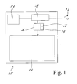
- Figure 1 shows an electrical apparatus 11, particularly an electrical household appliance (such as an oven, a washing machine, a dish washer, etc).
- an electrical household appliance such as an oven, a washing machine, a dish washer, etc.
- the appliance comprises operating elements 12 designed to perform a primary function of the apparatus. These operating elements may be of various types, such as a heating resistor in the case of an oven or other electric loads (motors, electric actuators, etc.) for other types of appliances.
- the appliance 11 incorporates control electronics 16.
- Such electronics advantageously comprises a user interface, which may include, for instance, a display screen 17 and/or a keyboard 18 for apparatus programming data input.
- the electronics 16 is designed to control the operating elements 12 of the appliance, e.g. by actuating operating element controlling switches.
- the appliance 11 comprises a power circuit 15 which is connected in operation between the power-distribution network 13 and the electronics 16, as clearly shown in Figure 2 .
- the power circuit 15 has two output terminals, at -5V and -12V respectively.
- the -12V line powers the switching elements of the apparatus 11 (relays and other switches).
- the -5V powers the logic part of the electronics 16.
- standby operation i.e. the operation in which the apparatus does not perform its primary function (for instance, in an oven, the function of heating the oven cavity)
- the -12V part is idle as the operating elements 12 of the apparatus are idle.
- the -12V line does not take part in standby consumption.
- the -5V powers the logic part of the electronics 16 in standby mode.
- the supervision unit of the appliance e.g. an oven
- the supervision unit of the appliance may be required to be always energized both for safety reasons, and to allow appliance programming through the interface 17, 18 of the electronics 16.
- the -5V terminal 24 depends on an electrolytic capacitor C4, which is used for power storage and voltage stabilization.
- the capacitor C4 is connected between the earth and the terminal 24, at the output "V out" of the integrated circuit U2.
- the integrated circuit U2 consists of a linear stabilizer constructed according to prior art techniques.
- a capacitor C7 is placed in parallel with the capacitor C4.
- the electrolytic capacitor C6 is connected to the input terminal "V in” of the integrated circuit U2 and to the earth at the opposite terminal
- the terminal "V in” is connected to the -12V output terminal of the power circuit.
- the switching power supply 23 is connected upstream from the capacitor C6 and downstream from the power-distribution network 13.
- Switching power supplies are known in the art and comprise a rectifier stage and, downstream from the rectifier stage, controlled switching means to keep a predetermined stabilized voltage at an output terminal of the power supply, advantageously at the ends of a capacitor.
- the switching power supply includes a single half-wave rectifier circuit comprising the diode D2, with the electrolytic capacitor C20 and the inductor L2 connected downstream therefrom to charge the electrolytic capacitor C5.
- the capacitor C5 is connected between the earth and the terminal 5, of the integrated circuit U1.
- the integrated circuit U1 which is constructed according to prior art techniques, comprises the switching means (e.g. transistors) of the switching power supply 23, controlled to obtain a stabilized voltage downstream from the switching power supply.
- switching means e.g. transistors
- the electrolytic capacitor C2 is connected to the terminal 2 of the integrated circuit U1, and to earth at the opposite terminal, via the diode D8.
- the resistor R3 is connected between the terminals 2 and 4 of the integrated circuit U1.
- the resistor R5 is connected between the positive pole of the capacitor C2 and the terminal 4 of the integrated circuit U1.
- the solar power supply is connected, in parallel with the capacitor C4, between the earth and the -5V terminal of the power circuit.
- the solar power supply 14 comprises a solar power source 19, advantageously in the form of a photovoltaic solar panel.
- the solar power source is constantly connected to the electronics to be powered, particularly to the -5V line, via a closed electric circuit having no switches, i.e. no elements controlled to open or close the electric circuit.
- the solar source 19 has at its ends a circuit branch including a forward-biased LED 22 and a reverse-biased Zener diode 21.
- a diode 20 is connected to an output branch of the solar power supply 14 connected to the terminal 24, whose bias prevents current flow when the solar power source 19 is idle and does not generate sufficient voltage to supply a voltage exceeding 5V to the ends of the solar power supply.
- the positive terminal of the source 19 is connected to earth.
- the charging voltage for C4, having the terminal 24 connected thereto, is supplied by the integrated circuit U2, which acts as a linear voltage regulator.
- the integrated circuit U1 draws -12V voltage from the electrolytic capacitor C6 and supplies it at -5V to the ends of the capacitor C4.
- the switching power supply 23 draws energy from the capacitor C5 for packet transfer thereof to the downstream capacitor C2, which is in turn connected to the capacitor C6.
- the capacitor C5, which is connected upstream from the integrated circuit U1 is supplied with mains voltage by the single half-wave rectifier provided by the diode D2.
- the switching power supply 23 comprises feedback control means, which monitor a voltage downstream from the switching means (here included in the integrated circuit U1) to compare it with a reference voltage, to control switching of the switching means and stabilize the output voltage of the power supply.
- the integrated circuit U1 monitors voltage at the ends of C2 through a feedback line consisting of the resistive divider R3-R5. When voltage at the ends of C2 drops below a preset value, the integrated circuit U2 drops an energy packet from C5 and transfers it to C2 by appropriately controlling its switching elements and repeating this step until the C2 voltage reaches the desired value.
- the solar power supply 14 supplies power to the electronics 16.
- the switching integrated circuit U1 finds that the capacitor C6 is charged and deviates no other energy packet from C5 to C6.
- the capacitor C5 remains in its charged state and does not draw power from the mains 13.
- Standby power consumption may be reduced, for instance, by 70%. The remaining 30% is consumed, which is required for operation of the passive network of U1.
- the voltage supplied by the source 19 is sufficient to circulate current in the Zener diode 21, and turns the LED 22 on. The user will be informed that standby operation is supplied with solar energy.
- the electronics 16 will be powered by the mains 13, and the current will not flow through the solar power supply 14 due to the presence of the diode 20.
- the apparatus of the invention affords considerable power savings, particularly in standby operation, in spite of its simple and inexpensive structure, with a small number of electronic components.
- a switching power supply (connected between the mains and the power terminal for the electronics) with a solar power supply (connected between the earth and the power terminal for the electronics) is particularly advantageous because it utilizes the natural self-regulating feature of the switching power supply to reduce mains power absorption when the solar source is adequately illuminated.
- the apparatus also requires no energy storage batteries, unlike the prior art.
- the user may be reliably and reassuringly informed of the power saving condition, without any particularly complex circuit arrangement.
- the presence of the diode 20 also avoids current recirculation into the solar panel 19 using a simple and inexpensive circuit configuration.
Landscapes
- Engineering & Computer Science (AREA)
- Power Engineering (AREA)
- Business, Economics & Management (AREA)
- Emergency Management (AREA)
- Direct Current Feeding And Distribution (AREA)
- Lock And Its Accessories (AREA)
- Control Of Electrical Variables (AREA)
Priority Applications (3)
| Application Number | Priority Date | Filing Date | Title |
|---|---|---|---|
| ES09425295.4T ES2661328T3 (es) | 2009-07-22 | 2009-07-22 | Aparato eléctrico con un suministro de energía solar |
| EP09425295.4A EP2278687B1 (fr) | 2009-07-22 | 2009-07-22 | Appareil électrique avec une source d'alimentation solaire |
| TR2018/02561T TR201802561T4 (tr) | 2009-07-22 | 2009-07-22 | Bir güneş enerjisi tedarikine sahip elektrikli cihaz. |
Applications Claiming Priority (1)
| Application Number | Priority Date | Filing Date | Title |
|---|---|---|---|
| EP09425295.4A EP2278687B1 (fr) | 2009-07-22 | 2009-07-22 | Appareil électrique avec une source d'alimentation solaire |
Publications (2)
| Publication Number | Publication Date |
|---|---|
| EP2278687A1 true EP2278687A1 (fr) | 2011-01-26 |
| EP2278687B1 EP2278687B1 (fr) | 2018-01-17 |
Family
ID=41130370
Family Applications (1)
| Application Number | Title | Priority Date | Filing Date |
|---|---|---|---|
| EP09425295.4A Not-in-force EP2278687B1 (fr) | 2009-07-22 | 2009-07-22 | Appareil électrique avec une source d'alimentation solaire |
Country Status (3)
| Country | Link |
|---|---|
| EP (1) | EP2278687B1 (fr) |
| ES (1) | ES2661328T3 (fr) |
| TR (1) | TR201802561T4 (fr) |
Cited By (2)
| Publication number | Priority date | Publication date | Assignee | Title |
|---|---|---|---|---|
| WO2017004800A1 (fr) * | 2015-07-08 | 2017-01-12 | 罗明镜 | Système d'éclairage solaire domestique |
| CN110942788A (zh) * | 2019-09-25 | 2020-03-31 | 苏州浪潮智能科技有限公司 | 一种多级备用电源的电源切换系统 |
Citations (4)
| Publication number | Priority date | Publication date | Assignee | Title |
|---|---|---|---|---|
| GB2270053A (en) * | 1992-06-18 | 1994-03-02 | Douglas Kitchener Gatward | Battery-powered bicycle. |
| EP0622883A2 (fr) | 1993-04-27 | 1994-11-02 | Canon Kabushiki Kaisha | Appareil de communication et son dispositif d'alimentation |
| EP1513240A2 (fr) | 2003-09-02 | 2005-03-09 | Marantz Japan, Inc. | Appareil d'alimentation de puissance de secours |
| WO2008074195A1 (fr) | 2006-12-20 | 2008-06-26 | Lijun Xuan | Dispositif d'alimentation à faible énergie |
-
2009
- 2009-07-22 ES ES09425295.4T patent/ES2661328T3/es active Active
- 2009-07-22 EP EP09425295.4A patent/EP2278687B1/fr not_active Not-in-force
- 2009-07-22 TR TR2018/02561T patent/TR201802561T4/tr unknown
Patent Citations (4)
| Publication number | Priority date | Publication date | Assignee | Title |
|---|---|---|---|---|
| GB2270053A (en) * | 1992-06-18 | 1994-03-02 | Douglas Kitchener Gatward | Battery-powered bicycle. |
| EP0622883A2 (fr) | 1993-04-27 | 1994-11-02 | Canon Kabushiki Kaisha | Appareil de communication et son dispositif d'alimentation |
| EP1513240A2 (fr) | 2003-09-02 | 2005-03-09 | Marantz Japan, Inc. | Appareil d'alimentation de puissance de secours |
| WO2008074195A1 (fr) | 2006-12-20 | 2008-06-26 | Lijun Xuan | Dispositif d'alimentation à faible énergie |
Cited By (3)
| Publication number | Priority date | Publication date | Assignee | Title |
|---|---|---|---|---|
| WO2017004800A1 (fr) * | 2015-07-08 | 2017-01-12 | 罗明镜 | Système d'éclairage solaire domestique |
| CN110942788A (zh) * | 2019-09-25 | 2020-03-31 | 苏州浪潮智能科技有限公司 | 一种多级备用电源的电源切换系统 |
| CN110942788B (zh) * | 2019-09-25 | 2021-08-20 | 苏州浪潮智能科技有限公司 | 一种多级备用电源的电源切换系统 |
Also Published As
| Publication number | Publication date |
|---|---|
| TR201802561T4 (tr) | 2018-03-21 |
| EP2278687B1 (fr) | 2018-01-17 |
| ES2661328T3 (es) | 2018-03-28 |
Similar Documents
| Publication | Publication Date | Title |
|---|---|---|
| KR100686281B1 (ko) | 병렬 접속된 인버터를 갖는 전원 시스템을 동작시키는방법 및 전력 변환 시스템 | |
| US8164932B2 (en) | Power converter with automatic mode switching | |
| KR19990081390A (ko) | 전원 공급 회로 | |
| CN210273593U (zh) | 低待机功耗的大功率电源电路及led显示控制系统 | |
| CN103250323A (zh) | 用于减少家用电器的待机状态能耗的电子控制装置和方法 | |
| US20100090534A1 (en) | Self-stopping electrical appliance | |
| CN113038652B (zh) | 电路控制系统和串联控制装置及其控制方法 | |
| CN114185277B (zh) | 一种家用电器及其控制方法 | |
| CN220156405U (zh) | 辅助电源的控制电路、辅助电源及电子设备 | |
| US6559625B2 (en) | Circuit arrangement and electrical appliance with an inductive load and a buck converter | |
| EP2278687B1 (fr) | Appareil électrique avec une source d'alimentation solaire | |
| CN209001651U (zh) | 配电柜及具有其的炒菜机供电系统 | |
| EP2406876B1 (fr) | Circuit d'alimentation pour alimenter un circuit de commutation | |
| CN110500696B (zh) | 一种控制电路及空调 | |
| JP2016086454A (ja) | 発電システム | |
| KR102069392B1 (ko) | 대기 모드를 갖는 가전 제품 및 상기 가전 제품의 작동 방법 | |
| JP2013031309A (ja) | パワーコンディショナ | |
| CA2492580A1 (fr) | Chute d'alimentation electrique a condensateur a interruption de neutralisation | |
| WO2004017482A3 (fr) | Systeme pour detecter une basse tension dans un appareil electrique | |
| KR102385805B1 (ko) | 전력스위치 구동 제어장치 | |
| EP2887516A1 (fr) | Régulateur de tension universel et procédé de dérivation d'une unité de régulation de tension dans un appareil de régulation de tension | |
| CN110086190A (zh) | 一种供电系统 | |
| EP4170269A1 (fr) | Thermorégulateur électronique conçu pour commander un appareil de réfrigération professionnelle | |
| EP1966553B1 (fr) | Appareil ménager | |
| CN201354537Y (zh) | 室内节能门锁 |
Legal Events
| Date | Code | Title | Description |
|---|---|---|---|
| PUAI | Public reference made under article 153(3) epc to a published international application that has entered the european phase |
Free format text: ORIGINAL CODE: 0009012 |
|
| AK | Designated contracting states |
Kind code of ref document: A1 Designated state(s): AT BE BG CH CY CZ DE DK EE ES FI FR GB GR HR HU IE IS IT LI LT LU LV MC MK MT NL NO PL PT RO SE SI SK SM TR |
|
| AX | Request for extension of the european patent |
Extension state: AL BA RS |
|
| 17P | Request for examination filed |
Effective date: 20110413 |
|
| 17Q | First examination report despatched |
Effective date: 20110418 |
|
| 17Q | First examination report despatched |
Effective date: 20111005 |
|
| GRAP | Despatch of communication of intention to grant a patent |
Free format text: ORIGINAL CODE: EPIDOSNIGR1 |
|
| STAA | Information on the status of an ep patent application or granted ep patent |
Free format text: STATUS: GRANT OF PATENT IS INTENDED |
|
| INTG | Intention to grant announced |
Effective date: 20170905 |
|
| GRAS | Grant fee paid |
Free format text: ORIGINAL CODE: EPIDOSNIGR3 |
|
| GRAA | (expected) grant |
Free format text: ORIGINAL CODE: 0009210 |
|
| STAA | Information on the status of an ep patent application or granted ep patent |
Free format text: STATUS: THE PATENT HAS BEEN GRANTED |
|
| AK | Designated contracting states |
Kind code of ref document: B1 Designated state(s): AT BE BG CH CY CZ DE DK EE ES FI FR GB GR HR HU IE IS IT LI LT LU LV MC MK MT NL NO PL PT RO SE SI SK SM TR |
|
| REG | Reference to a national code |
Ref country code: GB Ref legal event code: FG4D |
|
| REG | Reference to a national code |
Ref country code: CH Ref legal event code: EP |
|
| REG | Reference to a national code |
Ref country code: IE Ref legal event code: FG4D |
|
| REG | Reference to a national code |
Ref country code: DE Ref legal event code: R096 Ref document number: 602009050432 Country of ref document: DE Ref country code: AT Ref legal event code: REF Ref document number: 965044 Country of ref document: AT Kind code of ref document: T Effective date: 20180215 |
|
| REG | Reference to a national code |
Ref country code: ES Ref legal event code: FG2A Ref document number: 2661328 Country of ref document: ES Kind code of ref document: T3 Effective date: 20180328 |
|
| REG | Reference to a national code |
Ref country code: NL Ref legal event code: MP Effective date: 20180117 |
|
| REG | Reference to a national code |
Ref country code: LT Ref legal event code: MG4D |
|
| REG | Reference to a national code |
Ref country code: AT Ref legal event code: MK05 Ref document number: 965044 Country of ref document: AT Kind code of ref document: T Effective date: 20180117 |
|
| PG25 | Lapsed in a contracting state [announced via postgrant information from national office to epo] |
Ref country code: NL Free format text: LAPSE BECAUSE OF FAILURE TO SUBMIT A TRANSLATION OF THE DESCRIPTION OR TO PAY THE FEE WITHIN THE PRESCRIBED TIME-LIMIT Effective date: 20180117 |
|
| PG25 | Lapsed in a contracting state [announced via postgrant information from national office to epo] |
Ref country code: FI Free format text: LAPSE BECAUSE OF FAILURE TO SUBMIT A TRANSLATION OF THE DESCRIPTION OR TO PAY THE FEE WITHIN THE PRESCRIBED TIME-LIMIT Effective date: 20180117 Ref country code: NO Free format text: LAPSE BECAUSE OF FAILURE TO SUBMIT A TRANSLATION OF THE DESCRIPTION OR TO PAY THE FEE WITHIN THE PRESCRIBED TIME-LIMIT Effective date: 20180417 Ref country code: LT Free format text: LAPSE BECAUSE OF FAILURE TO SUBMIT A TRANSLATION OF THE DESCRIPTION OR TO PAY THE FEE WITHIN THE PRESCRIBED TIME-LIMIT Effective date: 20180117 Ref country code: CY Free format text: LAPSE BECAUSE OF FAILURE TO SUBMIT A TRANSLATION OF THE DESCRIPTION OR TO PAY THE FEE WITHIN THE PRESCRIBED TIME-LIMIT Effective date: 20180117 Ref country code: HR Free format text: LAPSE BECAUSE OF FAILURE TO SUBMIT A TRANSLATION OF THE DESCRIPTION OR TO PAY THE FEE WITHIN THE PRESCRIBED TIME-LIMIT Effective date: 20180117 |
|
| REG | Reference to a national code |
Ref country code: FR Ref legal event code: PLFP Year of fee payment: 10 |
|
| PG25 | Lapsed in a contracting state [announced via postgrant information from national office to epo] |
Ref country code: BG Free format text: LAPSE BECAUSE OF FAILURE TO SUBMIT A TRANSLATION OF THE DESCRIPTION OR TO PAY THE FEE WITHIN THE PRESCRIBED TIME-LIMIT Effective date: 20180417 Ref country code: AT Free format text: LAPSE BECAUSE OF FAILURE TO SUBMIT A TRANSLATION OF THE DESCRIPTION OR TO PAY THE FEE WITHIN THE PRESCRIBED TIME-LIMIT Effective date: 20180117 Ref country code: SE Free format text: LAPSE BECAUSE OF FAILURE TO SUBMIT A TRANSLATION OF THE DESCRIPTION OR TO PAY THE FEE WITHIN THE PRESCRIBED TIME-LIMIT Effective date: 20180117 Ref country code: IS Free format text: LAPSE BECAUSE OF FAILURE TO SUBMIT A TRANSLATION OF THE DESCRIPTION OR TO PAY THE FEE WITHIN THE PRESCRIBED TIME-LIMIT Effective date: 20180517 Ref country code: LV Free format text: LAPSE BECAUSE OF FAILURE TO SUBMIT A TRANSLATION OF THE DESCRIPTION OR TO PAY THE FEE WITHIN THE PRESCRIBED TIME-LIMIT Effective date: 20180117 Ref country code: PL Free format text: LAPSE BECAUSE OF FAILURE TO SUBMIT A TRANSLATION OF THE DESCRIPTION OR TO PAY THE FEE WITHIN THE PRESCRIBED TIME-LIMIT Effective date: 20180117 Ref country code: GR Free format text: LAPSE BECAUSE OF FAILURE TO SUBMIT A TRANSLATION OF THE DESCRIPTION OR TO PAY THE FEE WITHIN THE PRESCRIBED TIME-LIMIT Effective date: 20180418 |
|
| REG | Reference to a national code |
Ref country code: DE Ref legal event code: R097 Ref document number: 602009050432 Country of ref document: DE |
|
| PG25 | Lapsed in a contracting state [announced via postgrant information from national office to epo] |
Ref country code: EE Free format text: LAPSE BECAUSE OF FAILURE TO SUBMIT A TRANSLATION OF THE DESCRIPTION OR TO PAY THE FEE WITHIN THE PRESCRIBED TIME-LIMIT Effective date: 20180117 Ref country code: RO Free format text: LAPSE BECAUSE OF FAILURE TO SUBMIT A TRANSLATION OF THE DESCRIPTION OR TO PAY THE FEE WITHIN THE PRESCRIBED TIME-LIMIT Effective date: 20180117 |
|
| PGFP | Annual fee paid to national office [announced via postgrant information from national office to epo] |
Ref country code: ES Payment date: 20180801 Year of fee payment: 10 Ref country code: IT Payment date: 20180710 Year of fee payment: 10 Ref country code: FR Payment date: 20180731 Year of fee payment: 10 |
|
| PLBE | No opposition filed within time limit |
Free format text: ORIGINAL CODE: 0009261 |
|
| STAA | Information on the status of an ep patent application or granted ep patent |
Free format text: STATUS: NO OPPOSITION FILED WITHIN TIME LIMIT |
|
| PG25 | Lapsed in a contracting state [announced via postgrant information from national office to epo] |
Ref country code: CZ Free format text: LAPSE BECAUSE OF FAILURE TO SUBMIT A TRANSLATION OF THE DESCRIPTION OR TO PAY THE FEE WITHIN THE PRESCRIBED TIME-LIMIT Effective date: 20180117 Ref country code: SK Free format text: LAPSE BECAUSE OF FAILURE TO SUBMIT A TRANSLATION OF THE DESCRIPTION OR TO PAY THE FEE WITHIN THE PRESCRIBED TIME-LIMIT Effective date: 20180117 Ref country code: DK Free format text: LAPSE BECAUSE OF FAILURE TO SUBMIT A TRANSLATION OF THE DESCRIPTION OR TO PAY THE FEE WITHIN THE PRESCRIBED TIME-LIMIT Effective date: 20180117 Ref country code: SM Free format text: LAPSE BECAUSE OF FAILURE TO SUBMIT A TRANSLATION OF THE DESCRIPTION OR TO PAY THE FEE WITHIN THE PRESCRIBED TIME-LIMIT Effective date: 20180117 |
|
| PGFP | Annual fee paid to national office [announced via postgrant information from national office to epo] |
Ref country code: TR Payment date: 20180723 Year of fee payment: 10 Ref country code: GB Payment date: 20180719 Year of fee payment: 10 |
|
| 26N | No opposition filed |
Effective date: 20181018 |
|
| PGFP | Annual fee paid to national office [announced via postgrant information from national office to epo] |
Ref country code: DE Payment date: 20180928 Year of fee payment: 10 |
|
| PG25 | Lapsed in a contracting state [announced via postgrant information from national office to epo] |
Ref country code: SI Free format text: LAPSE BECAUSE OF FAILURE TO SUBMIT A TRANSLATION OF THE DESCRIPTION OR TO PAY THE FEE WITHIN THE PRESCRIBED TIME-LIMIT Effective date: 20180117 |
|
| REG | Reference to a national code |
Ref country code: CH Ref legal event code: PL |
|
| PG25 | Lapsed in a contracting state [announced via postgrant information from national office to epo] |
Ref country code: MC Free format text: LAPSE BECAUSE OF FAILURE TO SUBMIT A TRANSLATION OF THE DESCRIPTION OR TO PAY THE FEE WITHIN THE PRESCRIBED TIME-LIMIT Effective date: 20180117 Ref country code: LU Free format text: LAPSE BECAUSE OF NON-PAYMENT OF DUE FEES Effective date: 20180722 |
|
| REG | Reference to a national code |
Ref country code: BE Ref legal event code: MM Effective date: 20180731 |
|
| REG | Reference to a national code |
Ref country code: IE Ref legal event code: MM4A |
|
| PG25 | Lapsed in a contracting state [announced via postgrant information from national office to epo] |
Ref country code: CH Free format text: LAPSE BECAUSE OF NON-PAYMENT OF DUE FEES Effective date: 20180731 Ref country code: IE Free format text: LAPSE BECAUSE OF NON-PAYMENT OF DUE FEES Effective date: 20180722 Ref country code: LI Free format text: LAPSE BECAUSE OF NON-PAYMENT OF DUE FEES Effective date: 20180731 |
|
| PG25 | Lapsed in a contracting state [announced via postgrant information from national office to epo] |
Ref country code: BE Free format text: LAPSE BECAUSE OF NON-PAYMENT OF DUE FEES Effective date: 20180731 |
|
| PG25 | Lapsed in a contracting state [announced via postgrant information from national office to epo] |
Ref country code: MT Free format text: LAPSE BECAUSE OF NON-PAYMENT OF DUE FEES Effective date: 20180722 |
|
| REG | Reference to a national code |
Ref country code: DE Ref legal event code: R119 Ref document number: 602009050432 Country of ref document: DE |
|
| GBPC | Gb: european patent ceased through non-payment of renewal fee |
Effective date: 20190722 |
|
| PG25 | Lapsed in a contracting state [announced via postgrant information from national office to epo] |
Ref country code: DE Free format text: LAPSE BECAUSE OF NON-PAYMENT OF DUE FEES Effective date: 20200201 Ref country code: GB Free format text: LAPSE BECAUSE OF NON-PAYMENT OF DUE FEES Effective date: 20190722 |
|
| PG25 | Lapsed in a contracting state [announced via postgrant information from national office to epo] |
Ref country code: PT Free format text: LAPSE BECAUSE OF FAILURE TO SUBMIT A TRANSLATION OF THE DESCRIPTION OR TO PAY THE FEE WITHIN THE PRESCRIBED TIME-LIMIT Effective date: 20180117 Ref country code: HU Free format text: LAPSE BECAUSE OF FAILURE TO SUBMIT A TRANSLATION OF THE DESCRIPTION OR TO PAY THE FEE WITHIN THE PRESCRIBED TIME-LIMIT; INVALID AB INITIO Effective date: 20090722 |
|
| PG25 | Lapsed in a contracting state [announced via postgrant information from national office to epo] |
Ref country code: MK Free format text: LAPSE BECAUSE OF NON-PAYMENT OF DUE FEES Effective date: 20180117 Ref country code: FR Free format text: LAPSE BECAUSE OF NON-PAYMENT OF DUE FEES Effective date: 20190731 |
|
| PG25 | Lapsed in a contracting state [announced via postgrant information from national office to epo] |
Ref country code: IT Free format text: LAPSE BECAUSE OF NON-PAYMENT OF DUE FEES Effective date: 20190722 |
|
| REG | Reference to a national code |
Ref country code: ES Ref legal event code: FD2A Effective date: 20201201 |
|
| PG25 | Lapsed in a contracting state [announced via postgrant information from national office to epo] |
Ref country code: ES Free format text: LAPSE BECAUSE OF NON-PAYMENT OF DUE FEES Effective date: 20190723 |
|
| PG25 | Lapsed in a contracting state [announced via postgrant information from national office to epo] |
Ref country code: TR Free format text: LAPSE BECAUSE OF NON-PAYMENT OF DUE FEES Effective date: 20190722 |