EP2278730A2 - Procédé de traitement de données et station de base pour diversité de transmission en liaison descendante - Google Patents
Procédé de traitement de données et station de base pour diversité de transmission en liaison descendante Download PDFInfo
- Publication number
- EP2278730A2 EP2278730A2 EP10170024A EP10170024A EP2278730A2 EP 2278730 A2 EP2278730 A2 EP 2278730A2 EP 10170024 A EP10170024 A EP 10170024A EP 10170024 A EP10170024 A EP 10170024A EP 2278730 A2 EP2278730 A2 EP 2278730A2
- Authority
- EP
- European Patent Office
- Prior art keywords
- antenna port
- data symbol
- symbols
- antenna
- pair
- Prior art date
- Legal status (The legal status is an assumption and is not a legal conclusion. Google has not performed a legal analysis and makes no representation as to the accuracy of the status listed.)
- Withdrawn
Links
Images


Classifications
-
- H—ELECTRICITY
- H04—ELECTRIC COMMUNICATION TECHNIQUE
- H04B—TRANSMISSION
- H04B7/00—Radio transmission systems, i.e. using radiation field
- H04B7/02—Diversity systems; Multi-antenna system, i.e. transmission or reception using multiple antennas
- H04B7/04—Diversity systems; Multi-antenna system, i.e. transmission or reception using multiple antennas using two or more spaced independent antennas
- H04B7/06—Diversity systems; Multi-antenna system, i.e. transmission or reception using multiple antennas using two or more spaced independent antennas at the transmitting station
- H04B7/0686—Hybrid systems, i.e. switching and simultaneous transmission
- H04B7/0689—Hybrid systems, i.e. switching and simultaneous transmission using different transmission schemes, at least one of them being a diversity transmission scheme
-
- H—ELECTRICITY
- H04—ELECTRIC COMMUNICATION TECHNIQUE
- H04L—TRANSMISSION OF DIGITAL INFORMATION, e.g. TELEGRAPHIC COMMUNICATION
- H04L1/00—Arrangements for detecting or preventing errors in the information received
- H04L1/02—Arrangements for detecting or preventing errors in the information received by diversity reception
- H04L1/06—Arrangements for detecting or preventing errors in the information received by diversity reception using space diversity
- H04L1/0606—Space-frequency coding
-
- H—ELECTRICITY
- H04—ELECTRIC COMMUNICATION TECHNIQUE
- H04L—TRANSMISSION OF DIGITAL INFORMATION, e.g. TELEGRAPHIC COMMUNICATION
- H04L1/00—Arrangements for detecting or preventing errors in the information received
- H04L1/02—Arrangements for detecting or preventing errors in the information received by diversity reception
- H04L1/06—Arrangements for detecting or preventing errors in the information received by diversity reception using space diversity
- H04L1/0618—Space-time coding
-
- H—ELECTRICITY
- H04—ELECTRIC COMMUNICATION TECHNIQUE
- H04L—TRANSMISSION OF DIGITAL INFORMATION, e.g. TELEGRAPHIC COMMUNICATION
- H04L5/00—Arrangements affording multiple use of the transmission path
- H04L5/0001—Arrangements for dividing the transmission path
- H04L5/0014—Three-dimensional division
- H04L5/0023—Time-frequency-space
-
- H—ELECTRICITY
- H04—ELECTRIC COMMUNICATION TECHNIQUE
- H04L—TRANSMISSION OF DIGITAL INFORMATION, e.g. TELEGRAPHIC COMMUNICATION
- H04L5/00—Arrangements affording multiple use of the transmission path
- H04L5/003—Arrangements for allocating sub-channels of the transmission path
- H04L5/0044—Allocation of payload; Allocation of data channels, e.g. PDSCH or PUSCH
-
- H—ELECTRICITY
- H04—ELECTRIC COMMUNICATION TECHNIQUE
- H04L—TRANSMISSION OF DIGITAL INFORMATION, e.g. TELEGRAPHIC COMMUNICATION
- H04L1/00—Arrangements for detecting or preventing errors in the information received
- H04L2001/0098—Unequal error protection
Definitions
- the present invention relates to antenna port pairing and subcarrier mapping, and more particularly to a method and a system for antenna port pairing and subcarrier mapping for downlink transmit diversity, which provide better protection for important modulation symbols and improve the reliability of transmission.
- TxD Transmit Diversity
- UE user equipments
- SINR Signal to Interference plus Noise Ratio
- a communication system needs to adopt channel coding to check and correct errors so as to improve the reliability of the data transmission.
- channel coding For output of the channel encoder, different bit has different levels of importance. For example, the systematic bit generally has higher importance while the parity bit generally has lower importance.
- the downlink transmit diversity in 3GPP Long Term Evolution (LTE) adopts a scheme combining the Space-Frequency Block Code (SFBC) and Frequency Switch Transmit Diversity (FSTD), whose coding matrix is shown in Fig. 1 .
- SFBC Space-Frequency Block Code
- FSTD Frequency Switch Transmit Diversity
- a fixed antenna port pairing is adopted in this scheme, in which antenna port 0 and antenna port 2 are paired to transmit one SFBC block, and antenna port 1 and antenna port 3 are paired to transmit one SFBC block.
- LTE adopts fixed antenna port pairing is that the densities of the Reference Signals (RS) corresponding to the antenna ports are different.
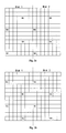
- Fig. 2a, 2b , 2c and 2d are schematic diagrams showing distributions of RSs of antenna ports 0, 1, 2, 3 respectively.
- LTE adopts this kind of antenna port paring mode (one high density RS antenna port together with a low density RS antenna port) is to achieve the performance of balance between two SFBC blocks, i.e. to protect the two SFBC blocks in a same way.
- the structure of the LTE transmit diversity transmitter is shown in Fig. 3 .
- the data symbols output by the modulator includes two parts: systematic symbol S; and parity symbol P.
- the systematic symbol is more important than the parity symbol.
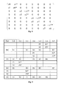
- Fig. 4 is a schematic diagram showing a distribution after the symbols in the transmit diversity coding matrix are mapped to the corresponding antenna ports and subcarriers according to the fixed antenna port paring in a 4-antenna system.
- R0, R1, R2 and R3 are reference signals on antenna ports 0, 1, 2 and 3 respectively. Since antenna ports 0 and 2 are a fixed pair and antenna ports 1 and 3 are a fixed pair, taking into account of the arrangement of the RSs at the antenna ports in slot 1, in slot 1, after the symbols are mapped to antenna ports and subcarriers, as shown in Fig.
- the parity symbol -P0* is mapped to the position nearest to the RS R2, i.e., -P0* is better protected than S0*, which will lead to the loss of the system performance.
- - P1*/ - P2*/ - P3* is better protected than S1* /S2* /S3*.
- An objective of the present invention is to provide a method and a base station for antenna port pairing and subcarrier mapping for downlink transmit diversity, which provide better protection for important modulation symbols and reduce system performance loss.
- an embodiment of the present invention provides a data processing method for downlink transmit diversity, comprising:
- the first antenna paring mode is: antenna port 0 and antenna port 3 are a pair, and antenna port 1 and antenna port 2 are a pair; and when the current slot is slot 2, the first antenna paring mode is: antenna port 0 and antenna port 2 are a pair, and antenna port 1 and antenna port 3 are a pair.
- the first antenna paring mode is: antenna port 0 and antenna port 3 are a pair, antenna port 1 and antenna port 2 are a pair, antenna port 4 and antenna port 7 are a pair and antenna port 5 and antenna port 6 are a pair; and when the current slot is slot 2, the first antenna paring mode is: antenna port 0 and antenna port 2 are a pair, antenna port 1 and antenna port 3 are a pair, antenna port 4 and antenna port 6 are a pair and antenna port 5 and antenna port 7 are a pair.
- the method further comprises:
- the sum of frequency domain distances from subcarriers in which symbols related to the first type data symbol are located to subcarriers in which RSs at corresponding antenna ports are located is made minimum by adjusting a sequence of space frequency block code blocks in the transmit diversity matrix corresponding to the data symbol group or by adjusting a sequence of symbols in a same space frequency block code block.
- the first type data symbol and the second type data symbol are a systematic symbol and a parity symbol respectively.
- an embodiment of the present invention provides a base station for downlink transmit diversity, comprising a modulator and wherein the base station further comprises:
- the first antenna paring mode is: antenna port 0 and antenna port 3 are a pair, and antenna port 1 and antenna port 2 are a pair; and when the current slot is slot 2, the first antenna paring mode is: antenna port 0 and antenna port 2 are a pair, and antenna port 1 and antenna port 3 are a pair.
- the first antenna paring mode is: antenna port 0 and antenna port 3 are a pair, antenna port 1 and antenna port 2 are a pair, antenna port 4 and antenna port 7 are a pair and antenna port 5 and antenna port 6 are a pair; and when the current slot is slot 2, the first antenna paring mode is: antenna port 0 and antenna port 2 are a pair, antenna port 1 and antenna port 3 are a pair, antenna port 4 and antenna port 6 are a pair and antenna port 5 and antenna port 7 are a pair.
- the base station further comprises:
- the sum of frequency domain distances from subcarriers in which symbols related to the first type data symbol are located to subcarriers in which RSs at corresponding antenna ports are located is made minimum by adjusting a sequence of space frequency block code blocks in the transmit diversity matrix corresponding to the data symbol group or by adjusting a sequence of symbols in a same space frequency block code block.
- the first type data symbol and the second type data symbol are a systematic symbol and a parity symbol respectively.
- data symbols in a first data symbol sequence including the first type data symbol and the second type data symbol output by the modulator are sequenced and grouped and a second data symbol sequence is obtained.
- the second data symbol sequence includes at least one data symbol group, and in the data symbol group, the first type data symbol and the second type data symbol are arranged in an interval so that it is possible to allocate all important symbols to high reliable subcarriers.
- the first antenna port paring mode corresponding to the current slot is determined according to the distribution of RSs in the current slot, wherein, in the current slot, after the antenna port and subcarrier mapping is performed on the symbols in the transmit diversity matrix corresponding to the data symbol group according to the first antenna port paring mode, among two symbols mapped to a same antenna port, a subcarrier in which a symbol related to the first type data symbol is located is nearer to a subcarrier in which a reference signal at the same antenna port is located. Therefore, the first type data symbol obtain better protection and the system performance loss is reduced.
- the antenna port and subcarrier mapping is performed on the symbols in the transmit diversity matrix according to the first antenna port paring mode, wherein after the antenna port and subcarrier mapping is performed on the symbols in the transmit diversity matrix according to the first antenna port paring mode, a sum of frequency domain distances from subcarriers in which symbols related to the first type data symbol are located to subcarriers in which RSs at corresponding antenna ports are located is minimum. Therefore, the first type data symbol obtains further protection.
- Fig. 1 is a schematic diagram showing a LTE transmit diversity coding matrix when a fixed antenna port pairing is adopted;
- Fig. 2a to Fig. 2d are schematic diagrams showing distributions of RSs at antenna ports 1-4 respectively in a 4-antenna system
- Fig. 3 is a schematic diagram showing a structure of an LTE transmit diversity transmitter
- Fig. 4 is a schematic diagram showing a distribution after symbols in a transmit diversity coding matrix are mapped to antenna ports and subcarriers when a fixed antenna port paring mode is adopted in a 4-antenna system;
- Fig. 5 is a flow chart showing a data processing method for downlink transmit diversity according to an embodiment of the present invention
- Fig. 6 is a schematic diagram showing a distribution after symbols in a transmit diversity coding matrix are mapped to antenna ports and subcarriers when a fixed antenna port paring mode is adopted in a 4-antenna system;
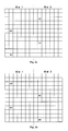
- Figs. 7a-7b are schematic diagrams showing distributions of RSs at antenna ports in an 8-antenna system in slot 1 and slot 2 respectively;
- Fig. 8 is a schematic diagram showing a LTE transmit diversity coding matrix in the 8-antenna system
- Fig. 9 is a schematic diagram showing a distribution after symbols in the transmit diversity coding matrix are mapped to antenna ports and subcarriers when the antenna port paring mode according to the embodiment of the present invention is adopted in slot 1 in the 8-antenna system;
- Fig. 10 is a schematic diagram showing a distribution after symbols in the transmit diversity coding matrix are mapped to antenna ports and subcarriers when the antenna port paring mode according to the embodiment of the present invention is adopted in slot 2 in the 8-antenna system;
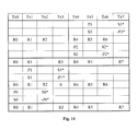
- Fig. 11 is a schematic diagram showing a symbol distribution in a first slot after the antenna port and subcarrier mapping is performed on symbols in a former transmit diversity matrix and in a new transmit diversity matrix by using a first antenna port paring mode;
- Fig. 12 is a schematic diagram showing a symbol distribution in a first slot after the antenna port and subcarrier mapping is performed on symbols in a former transmit diversity matrix and in a new transmit diversity matrix by using a first antenna port paring mode;
- Figs. 13-15 are simulation result diagrams using the method of the embodiment of the present invention.
- first type symbols and second type symbols are tried to be arranged in intervals by resequencing data symbols output by the modulator and important data symbols are mapped to subcarriers with higher reliabilities (near to RSs) by performing dynamic antenna port paring and subcarrier mapping, wherein the first type symbols are more important than the second type symbols.
- a data processing method for downlink transmit diversity includes the following steps.
- sequences and grouping step 51 data symbols in a first data symbol sequence including a first type data symbol (named as A for simplicity) and a second type data symbol (named as B for simplicity) output by the modulator are sequenced and grouped and a second data symbol sequence is obtained.
- the second data symbol sequence includes a third data symbol sequence, which is comprised by data symbol groups and in each of the data symbol groups, the first type data symbol and the second type data symbol are arranged in an interval.
- the second data symbol sequence includes at least one data symbol group in which A and B are arranged in an interval. An importance of a symbol related to A (including A itself) is higher than that of a symbol related with B.
- the second data symbol sequence should include data symbol groups as many as possible.
- the number of A equals to that of B and all the data symbol groups in the second data symbol sequence may be arranged in ABAB mode.
- the second data symbol sequence is the same as the third data symbol sequence.
- the modulator when the number of A is larger than that of B, the remaining As are arranged in AAAA mode and other data symbol groups are arranged in ABAB mode.
- the third data symbol sequence is part of the second data symbol sequence.
- the remaining Bs are arranged in BBBB mode and other data symbol groups are arranged in ABAB mode.
- the third data symbol sequence is part of the second data symbol sequence.
- the second data symbol sequence will be ABABABABABABABABABABBBBB and the third data symbol sequence will be ABABABABABABABABABAB, in which the data symbol group is ABAB.
- the importance of modulated output symbols is not differentiated. If the data symbols input to the space time code matrix are all important data symbols (systematic symbol S), taking into account of the characteristic of SFBC, some important data symbols must be allocated to low reliable subcarriers, which will reduce the transmission reliability.
- systematic symbol S systematic symbol S
- the important data symbols and unimportant data symbols are arranged in intervals so that such a resequenced group may be sufficiently adapt to the characteristic of the transmit coding matrix and all important data symbols can be allocated to high reliable subcarriers.
- the first antenna port paring mode corresponding to the current slot is determined according to a distribution of the RS at the antenna port in the current slot.
- the first antenna port paring mode has the following characteristics.
- the subcarrier in which the symbol related to A (including A itself and A* or -A*, wherein the symbol of A is decided by the position of A in the data symbol group) is located is nearer to the subcarrier in which the RS at the same antenna port is located.
- the absolute value of the central frequency difference between the subcarrier in which the symbol related to A is located and the subcarrier in which the RS at the same antenna port is located is less than the absolute value of the central frequency difference between the subcarrier in which the symbol related to B is located and the subcarrier in which the RS at the same antenna port is located.
- the symbols mapped to the same antenna port is A (assuming mapped to subcarrier a) and B (assuming mapped to subcarrier b), or A* (assuming mapped to subcarrier c) and -B* (assuming mapped to subcarrier d).
- subcarrier a is nearer to the subcarrier in which the RS at the antenna port where A is at is located than subcarrier b and at the same time
- subcarrier c is nearer to the subcarrier in which the RS at the antenna port where A* is at is located than subcarrier d.
- a first mapping processing step 53 for OFDM symbols including RSs, the antenna port and subcarrier mapping is performed on the symbols in the transmit diversity matrix corresponding to the data symbol group according to the first antenna port paring mode in the current slot by utilizing frequency switching diversity technology.
- the antenna port and subcarrier mapping processing is performed according to the conventional antenna port and subcarrier mapping processing method.
- a transmit processing step 54 after the symbols mapped to the subcarriers are subjected to the inverse fast fourier transform and cyclic prefix insertion processing, they are mapped to the physical antenna for transmission.
- the subcarrier mapping scheme has been regulated in related standards of LTE and it will be described in detail with reference to step 53 here.
- the symbols in the corresponding transmit diversity matrix include A1, B1, A2, B2, A1*, - B1*, A2*, - B2*.
- A1*, - B 1 *, A2* and - B2* are determined correspondingly, wherein - B1* is mapped to the subcarrier in which A1 is located, A1* is mapped to the subcarrier in which B1 is located, - B2* is mapped to the subcarrier in which A2 is located, and A2* is mapped to the subcarrier in which B2 is located.
- one antenna port a is selected for A1 and B1 (assuming that the RS at antenna port a is located in subcarrier 3) first and A1 and B1 are mapped to the subcarrier 1 and subcarrier 2, wherein the frequency domain distance between subcarrier 1 and subcarrier 3 is less than that between subcarrier 2 and subcarrier 3.
- antenna port paring mode corresponding to the current slot assuming antenna port a and antenna port b (assuming RS at antenna port b is in subcarrier 4) are a pair, A1* and -B1* will be mapped to antenna port b and subcarriers 2 and 1, wherein the frequency domain distance between subcarrier 2 and subcarrier 4 is less than that between subcarrier 1 and subcarrier 4.
- the antenna port paring mode corresponding to the current slot needs to be determined according to the distribution mode of RS at the antenna port in the current slot. Since according to the prior art, slot 1 cannot not protect important symbols well, then slot 1 will be taken as an example to illustrate.
- Fig. 2a the distributions of RSs are shown in Fig. 2a to Fig. 2d .
- Fig. 2c and Fig. 2d show that the RSs at antenna port 2 and antenna port 3 are not symmetrically distributed, i.e. the distributions of RSs at antenna port 2 and antenna port 3 in slot 1 are different from those in slot 2. Therefore, according to the above differences, in the embodiment of the present invention, for slot 1, antenna port 0 and antenna port 3 are a pair, and antenna port 1 and antenna port 2 are a pair. According to this paring mode, in slot 1, after symbols are mapped to the antenna ports and subcarriers, as shown in Fig.
- S0 is mapped to antenna port 0 and the subcarrier in which S0 is located is adjacent to the subcarrier in which R0 at antenna port 0 is located. Therefore, S0 can obtain best protection.
- S0* is mapped to antenna port 3 and the subcarrier in which S3 is located is adjacent to the subcarrier in which R3 at antenna port 3 is located. Therefore, S0* can obtain best protection also. Therefore, symbols S0 and S0* related to the systematic bit on the same SFBC both obtain best protection.
- Fig. 6 shows that in slot 1, symbols (S0, S0*, S1, S1*, S2, S2*, S3, S3*) related to the systematic bit also obtain best protection.
- antenna port 0 and antenna port 2 are a pair and antenna port 1 and antenna port 3 are a pair.
- symbols (S0, S0*, S1, S1*, S2, S2*, S3, S3*) related to the systematic bit also obtain best protection.
- the distributions of RSs are shown in Fig. 7a and Fig. 7b and the diversity coding matrix is shown in Fig. 8 .
- antenna port 0 and antenna port 2 are a pair
- antenna port 4 and antenna port 7 are a pair
- antenna port 5 and antenna port 6 are a pair.
- S0 is mapped to antenna port 0 and the subcarrier in which S0 is located is adjacent to the subcarrier in which R0 at antenna port 0 is located. Therefore, S0 can obtain best protection.
- S0* is mapped to antenna port 3 and the subcarrier in which S3 is located is adjacent to the subcarrier in which R3 at antenna port 3 is located. Therefore, S0* can obtain best protection also.
- antenna port 0 and antenna port 2 are a pair and antenna port 1 and antenna port 3 are a pair and antenna port 4 and antenna port 6 are a pair.
- symbols (S0, S0*, S1, S1*, S2, S2*, S3, S3*) related to the systematic bit also obtain best protection.
- a second mapping processing step for OFDM symbols not including RSs, in the current slot, the antenna port and subcarrier mapping is performed on the symbols in the transmit diversity matrix corresponding to the data symbol group according to the first antenna port paring mode, wherein after the antenna port and subcarrier mapping is performed on the symbols in the new transmit diversity matrix according to the first antenna port paring mode, the sum of frequency domain distances from the subcarriers in which comparatively important symbols are located to the subcarriers in which RSs at the corresponding antenna ports are located is minimum.
- the table on the left of Fig. 11 is a schematic diagram showing a symbol distribution in a first slot after the antenna port and subcarrier mapping is performed on symbols in a former transmit diversity matrix and in a new transmit diversity matrix by using a first antenna port paring mode.
- Data symbol groups S0P0S1P1 and S2P2S3P3 are taken as examples to illustrate.
- the data symbol group S2P2S3P3 is taken as an example to illustrate.
- the table on the left of Fig. 12 is a schematic diagram showing a symbol distribution in a second slot after the antenna port and subcarrier mapping is performed on symbols in a former transmit diversity matrix and in a new transmit diversity matrix by using a first antenna port paring mode.
- Data symbol groups SOPOS1P1 and S2P2S3P3 are taken as examples to illustrate.
- the data symbol group S2P2S3P3 is taken as an example to illustrate.
- the base station includes a modulator, physical antennas, and a sequencing and grouping module is for sequencing and grouping data symbols in a first data symbol sequence including a first type data symbol (named as A for simplicity) and a second type data symbol (named as B for simplicity) output by the modulator and obtaining a second data symbol sequence;
- the second data symbol sequence includes a third data symbol sequence, which is comprised by data symbol groups and in each of the data symbol groups, the first type data symbol and the second type data symbol are arranged in an interval and from another aspect, the second data symbol sequence includes at least one data symbol group in which A and B are arranged in an interval; an importance of a symbol related to A (including A itself) is higher than that of a symbol related with B.
- the second data symbol sequence should include data symbol groups as many as possible.
- the number of A equals to that of B and all the data symbol groups in the second data symbol sequence may be arranged in ABAB mode.
- the modulator when the number of A is larger than that of B, the remaining As are arranged in AAAA mode and other data symbol groups are arranged in ABAB mode.
- the remaining Bs are arranged in BBBB mode and other data symbol groups are arranged in ABAB mode.
- the importance of modulated output symbols is not differentiated. If the data symbols input to the space time code matrix are all important data symbols (systematic symbol S), taking into account of the characteristic of SFBC, some important data symbols must be allocated to low reliable subcarriers, which will reduce the transmission reliability.
- systematic symbol S systematic symbol S
- the important data symbols and unimportant data symbols are arranged in intervals so that such a resequenced group may be sufficiently adapt to the characteristic of the transmit coding matrix and all important data symbols can be allocated to high reliable subcarriers.
- An antenna port paring module is for determining the first antenna port paring mode corresponding to the current slot according to a distribution of the RS at the antenna port in the current slot.
- the first antenna port paring mode has the following charateristics.
- the subcarrier in which the symbol related to A is located is nearer to the subcarrier in which the RS at the same antenna port is located.
- the absolute value of the central frequency difference between the subcarrier in which the symbol related to A is located and the subcarrier in which the RS at the same antenna port is located is less than the absolute value of the central frequency difference between the subcarrier in which the symbol related to B is located and the subcarrier in which the RS at the same antenna port is located.
- the symbols mapped to the same antenna port is A (assuming mapped to subcarrier a) and B (assuming mapped to subcarrier b), or A* (assuming mapped to subcarrier c) and -B* (assuming mapped to subcarrier d).
- subcarrier a is nearer to the subcarrier in which the RS at the antenna port where A is at is located than subcarrier b and at the same time
- subcarrier c is nearer to the subcarrier in which the RS at the antenna port where A* is at is located than subcarrier d.
- a first mapping processing module is for performing the antenna port and subcarrier mapping on the symbols in the transmit diversity matrix corresponding to the data symbol group according to the first antenna port paring mode in the current slot by utilizing frequency switching diversity technology, for OFDM symbols including RSs.
- the antenna port and subcarrier mapping processing is performed according to the conventional antenna port and subcarrier mapping processing method.
- a transmit processing module is for performing the inverse fast fourier transform and cyclic prefix insertion processing on the symbols mapped to the subcarriers and then mapping them to the physical antenna for transmission.
- the following module is further included.
- a second mapping processing module is for performing the antenna port and subcarrier mapping on the symbols in the transmit diversity matrix corresponding to the data symbol group according to the first antenna port paring mode for OFDM symbols not including RSs in the current slot by utilizing the frequency switching diversity technology, wherein after the antenna port and subcarrier mapping is performed on the symbols in the transmit diversity matrix according to the first antenna port paring mode, the sum of frequency domain distances from the subcarriers in which comparatively important symbols are located to the subcarriers in which RSs at the corresponding antenna ports are located is minimum.
- the scheme proposed is simulated and compared with the conventional scheme.
- the simulation conditions are as follows.
- Multi-antenna channel uncorrelated TU6 channel.
- Antenna configuration 4 antennas for the base station and 4 antennas for the mobile station.
- Channel estimation algorithm minimum mean square error estimation and linear interpolation.
- Frame structure and RS position same as TS 36.211 and TS 36.212 standards.
- Fig. 13 shows a frame error rate of turbo code in a case of QPSK modulation, 10 resource blocks and 1/2 or 2/3 code rates.
- Fig. 13 shows that the scheme of the embodiment can obtain lower frame error rate than the LET scheme.
- Fig. 14 shows a frame error rate of turbo code in a case of 16QAM modulation, 10 resource blocks and 1/2 or 2/3 code rates.
- Fig. 14 shows that in the case of high order modulation, the scheme of the embodiment can also obtain lower frame error rate than the LET scheme.
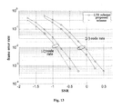
- Fig. 15 shows a frame error rate of turbo code in a case of 16QAM modulation, 2 or 10 resource blocks and 1/2 code rate.
- Fig. 14 shows that in the case of fewer resource blocks, the scheme of the embodiment can also obtain lower frame error rate than the LET scheme.
Landscapes
- Engineering & Computer Science (AREA)
- Signal Processing (AREA)
- Computer Networks & Wireless Communication (AREA)
- Radio Transmission System (AREA)
Applications Claiming Priority (1)
| Application Number | Priority Date | Filing Date | Title |
|---|---|---|---|
| CN200910152170.0A CN101958737B (zh) | 2009-07-20 | 2009-07-20 | 一种用于下行发送分集的数据处理方法及基站 |
Publications (2)
| Publication Number | Publication Date |
|---|---|
| EP2278730A2 true EP2278730A2 (fr) | 2011-01-26 |
| EP2278730A3 EP2278730A3 (fr) | 2015-09-23 |
Family
ID=43063458
Family Applications (1)
| Application Number | Title | Priority Date | Filing Date |
|---|---|---|---|
| EP10170024.3A Withdrawn EP2278730A3 (fr) | 2009-07-20 | 2010-07-19 | Procédé de traitement de données et station de base pour diversité de transmission en liaison descendante |
Country Status (4)
| Country | Link |
|---|---|
| US (1) | US8385453B2 (fr) |
| EP (1) | EP2278730A3 (fr) |
| JP (1) | JP5588772B2 (fr) |
| CN (1) | CN101958737B (fr) |
Families Citing this family (14)
| Publication number | Priority date | Publication date | Assignee | Title |
|---|---|---|---|---|
| US8384551B2 (en) | 2008-05-28 | 2013-02-26 | MedHab, LLC | Sensor device and method for monitoring physical stresses placed on a user |
| CN101719888B (zh) * | 2009-11-10 | 2013-03-20 | 中兴通讯股份有限公司 | 高级长期演进系统中参考信号序列的映射系统及方法 |
| US9036583B2 (en) * | 2010-07-16 | 2015-05-19 | Lg Electronics Inc. | Transmission method and apparatus for carrier aggregation and uplink MIMO |
| GB2493154A (en) | 2011-07-25 | 2013-01-30 | Nec Corp | Communicating control channel reference signal patterns in the control region of a sub-frame in a cellular communication system |
| US11974295B2 (en) | 2011-07-25 | 2024-04-30 | Nec Corporation | Communication system |
| US9282897B2 (en) | 2012-02-13 | 2016-03-15 | MedHab, LLC | Belt-mounted movement sensor system |
| CN103368696A (zh) * | 2012-03-26 | 2013-10-23 | 普天信息技术研究院有限公司 | 一种下行传输方法和装置 |
| US9320003B2 (en) * | 2013-11-27 | 2016-04-19 | Cisco Technology, Inc. | Detecting a narrow band ranging signal in an OFDM frame |
| WO2017092383A1 (fr) * | 2015-12-03 | 2017-06-08 | 华为技术有限公司 | Procédé d'émission multi-antenne sous un réseau de co-cellules, et station de base |
| WO2017132969A1 (fr) * | 2016-02-04 | 2017-08-10 | 华为技术有限公司 | Procédé et dispositif d'émission de signal de référence |
| US10084516B2 (en) | 2016-05-11 | 2018-09-25 | Huawei Technologies Canada Co., Ltd. | Antenna sub-array beam modulation |
| EP3769436A1 (fr) * | 2018-03-22 | 2021-01-27 | Telefonaktiebolaget Lm Ericsson (Publ) | Diversité de transmission de signaux |
| US11627590B2 (en) * | 2019-09-30 | 2023-04-11 | Qualcomm Incorporated | Scheduling network resources in wireless communication devices |
| CN119030568A (zh) * | 2024-08-05 | 2024-11-26 | 中国移动通信有限公司研究院 | 一种信号增强方法、装置、信号发射端、介质及程序产品 |
Family Cites Families (15)
| Publication number | Priority date | Publication date | Assignee | Title |
|---|---|---|---|---|
| US5029333A (en) * | 1989-12-07 | 1991-07-02 | Northern Telecom Limited | Communications system |
| KR100539924B1 (ko) * | 2003-07-08 | 2005-12-28 | 삼성전자주식회사 | 직교 주파수 분할 다중 방식을 사용하는 이동 통신시스템에서 채널 추정 시스템 및 방법 |
| EP3562058B1 (fr) * | 2004-03-15 | 2022-04-27 | Apple Inc. | Conception de pilote pour systèmes ofdm dotés de quatre antennes de transmission |
| WO2006019250A1 (fr) * | 2004-08-17 | 2006-02-23 | Samsung Electronics Co., Ltd. | Dispositif et procede de codage de bloc espace-temps-frequence pour de meilleures performances |
| US7593472B2 (en) * | 2004-10-22 | 2009-09-22 | Integrated System Solution Corp. | Methods and apparatus for circulation transmissions for OFDM-based MIMO systems |
| JP2007135021A (ja) * | 2005-11-11 | 2007-05-31 | Hitachi Communication Technologies Ltd | マルチキャリア通信における符号化信号配置方法及び通信装置 |
| KR20080113097A (ko) * | 2006-04-05 | 2008-12-26 | 에이저 시스템즈 인크 | 이동 단말용 hsdpa 코프로세서 |
| US7991063B2 (en) * | 2007-06-06 | 2011-08-02 | Samsung Electronics Co., Ltd | Transmission symbols mapping for antenna diversity |
| US8369450B2 (en) * | 2007-08-07 | 2013-02-05 | Samsung Electronics Co., Ltd. | Pilot boosting and traffic to pilot ratio estimation in a wireless communication system |
| KR101520667B1 (ko) * | 2007-09-10 | 2015-05-18 | 엘지전자 주식회사 | 다중 안테나 시스템에서의 파일럿 부반송파 할당 방법 |
| WO2009044735A1 (fr) * | 2007-10-02 | 2009-04-09 | Sharp Kabushiki Kaisha | Dispositif de transmission multiporteuse |
| CN101442389B (zh) * | 2007-11-23 | 2013-02-13 | 华为技术有限公司 | 一种多天线系统的数据发送、接收方法及装置 |
| US20100067512A1 (en) * | 2008-09-17 | 2010-03-18 | Samsung Electronics Co., Ltd. | Uplink transmit diversity schemes with 4 antenna ports |
| WO2010050757A2 (fr) * | 2008-10-30 | 2010-05-06 | Lg Electronics Inc. | Procédé de transmission de signaux de référence en liaison descendante dans un système de communication sans fil à antennes multiples |
| US8494066B2 (en) * | 2009-07-28 | 2013-07-23 | Broadcom Corporation | Method and system for low complexity channel estimation in OFDM communication networks using circular convolution |
-
2009
- 2009-07-20 CN CN200910152170.0A patent/CN101958737B/zh not_active Expired - Fee Related
-
2010
- 2010-07-09 US US12/833,881 patent/US8385453B2/en active Active
- 2010-07-19 EP EP10170024.3A patent/EP2278730A3/fr not_active Withdrawn
- 2010-07-20 JP JP2010162997A patent/JP5588772B2/ja not_active Expired - Fee Related
Non-Patent Citations (1)
| Title |
|---|
| None |
Also Published As
| Publication number | Publication date |
|---|---|
| JP2011024218A (ja) | 2011-02-03 |
| CN101958737A (zh) | 2011-01-26 |
| EP2278730A3 (fr) | 2015-09-23 |
| CN101958737B (zh) | 2014-08-06 |
| JP5588772B2 (ja) | 2014-09-10 |
| US8385453B2 (en) | 2013-02-26 |
| US20110013713A1 (en) | 2011-01-20 |
Similar Documents
| Publication | Publication Date | Title |
|---|---|---|
| EP2278730A2 (fr) | Procédé de traitement de données et station de base pour diversité de transmission en liaison descendante | |
| US7940640B2 (en) | Adaptive orthogonal scheduling for virtual MIMO system | |
| KR101543291B1 (ko) | 미모 무선 통신 시스템에서 안테나 매핑을 위한 장치 및 방법 | |
| CN102308489B (zh) | 在mimo无线通信系统中发送上行链路信号的装置及其方法 | |
| KR101534349B1 (ko) | Stbc 기법을 이용한 데이터 전송방법 | |
| EP2030341B1 (fr) | Appareil de traitement de signal reçu, procédé associé et procédé de sélection de règle de mappage | |
| US20110142076A1 (en) | Data transmission method using stbc scheme | |
| SG177735A1 (en) | Wireless communication device and wireless communication method | |
| US20110110307A1 (en) | Data transmission apparatus using multiple antennas and method thereof | |
| KR20100002064A (ko) | Sc-fdma 시스템에서 전송 다이버시티를 이용한 데이터 전송장치 및 방법 | |
| EA030779B1 (ru) | Базовая станция, терминал, система связи, способ связи и интегральная схема | |
| WO2010032997A2 (fr) | Procédé de transmission basé sur stbc tenant compte du nombre de symboles dans un intervalle | |
| KR20100004845A (ko) | 파일롯 서브캐리어 할당을 사용하는 복수개의 송신 안테나를 갖는 무선 통신 시스템 | |
| KR20100002089A (ko) | 무선통신 시스템에서 전송 다이버시티를 이용한 데이터 전송장치 및 방법 | |
| US8750276B2 (en) | Transmission apparatus, receiving apparatus, and radio communication method | |
| CN114244408B (zh) | 一种基站、用户设备中的用于多天线传输的方法和装置 | |
| US20050239488A1 (en) | Multi-carrier communication method and multi-carrier communication method | |
| KR101513035B1 (ko) | 다중 안테나를 갖는 이동 통신 시스템에서의 데이터 전송 방법 | |
| KR101527018B1 (ko) | 슬롯 내 심볼 개수를 고려한 stbc 기반 신호 전송 방법 | |
| KR20090055468A (ko) | 다수의 송신 안테나를 가진 시스템에서의 파일롯 신호 송수신 방법 | |
| CN108418654B (zh) | 一种信号检测方法及装置 | |
| KR101527022B1 (ko) | 다중안테나를 갖는 무선 통신 시스템에서 파일럿 전송 방법 | |
| KR20170133147A (ko) | 통신 시스템에서 신호 처리 방법 및 장치 | |
| Li et al. | A Novel Subcarrier Mapping Scheme for EUTRA Downlink Transmit Diversity | |
| KR20100014749A (ko) | 다중 안테나 시스템에서 데이터 전송 방법 |
Legal Events
| Date | Code | Title | Description |
|---|---|---|---|
| PUAI | Public reference made under article 153(3) epc to a published international application that has entered the european phase |
Free format text: ORIGINAL CODE: 0009012 |
|
| AK | Designated contracting states |
Kind code of ref document: A2 Designated state(s): AL AT BE BG CH CY CZ DE DK EE ES FI FR GB GR HR HU IE IS IT LI LT LU LV MC MK MT NL NO PL PT RO SE SI SK SM TR |
|
| AX | Request for extension of the european patent |
Extension state: BA ME RS |
|
| PUAL | Search report despatched |
Free format text: ORIGINAL CODE: 0009013 |
|
| AK | Designated contracting states |
Kind code of ref document: A3 Designated state(s): AL AT BE BG CH CY CZ DE DK EE ES FI FR GB GR HR HU IE IS IT LI LT LU LV MC MK MT NL NO PL PT RO SE SI SK SM TR |
|
| AX | Request for extension of the european patent |
Extension state: BA ME RS |
|
| RIC1 | Information provided on ipc code assigned before grant |
Ipc: H04L 5/00 20060101ALI20150819BHEP Ipc: H04L 1/06 20060101ALI20150819BHEP Ipc: H04L 1/00 20060101ALN20150819BHEP Ipc: H04B 7/06 20060101AFI20150819BHEP |
|
| 17P | Request for examination filed |
Effective date: 20160323 |
|
| RBV | Designated contracting states (corrected) |
Designated state(s): AL AT BE BG CH CY CZ DE DK EE ES FI FR GB GR HR HU IE IS IT LI LT LU LV MC MK MT NL NO PL PT RO SE SI SK SM TR |
|
| 17Q | First examination report despatched |
Effective date: 20170223 |
|
| GRAP | Despatch of communication of intention to grant a patent |
Free format text: ORIGINAL CODE: EPIDOSNIGR1 |
|
| INTG | Intention to grant announced |
Effective date: 20170804 |
|
| RIC1 | Information provided on ipc code assigned before grant |
Ipc: H04L 5/00 20060101ALI20170724BHEP Ipc: H04L 1/06 20060101ALI20170724BHEP Ipc: H04B 7/06 20060101AFI20170724BHEP Ipc: H04L 1/00 20060101ALN20170724BHEP |
|
| STAA | Information on the status of an ep patent application or granted ep patent |
Free format text: STATUS: THE APPLICATION IS DEEMED TO BE WITHDRAWN |
|
| 18D | Application deemed to be withdrawn |
Effective date: 20171215 |