EP2278827A1 - Procedé pour l'adaptation individuelle d'un appareil auditif - Google Patents
Procedé pour l'adaptation individuelle d'un appareil auditif Download PDFInfo
- Publication number
- EP2278827A1 EP2278827A1 EP10177370A EP10177370A EP2278827A1 EP 2278827 A1 EP2278827 A1 EP 2278827A1 EP 10177370 A EP10177370 A EP 10177370A EP 10177370 A EP10177370 A EP 10177370A EP 2278827 A1 EP2278827 A1 EP 2278827A1
- Authority
- EP
- European Patent Office
- Prior art keywords
- audio signal
- loudness
- level
- function
- frequency
- Prior art date
- Legal status (The legal status is an assumption and is not a legal conclusion. Google has not performed a legal analysis and makes no representation as to the accuracy of the status listed.)
- Withdrawn
Links
Images


Classifications
-
- H—ELECTRICITY
- H04—ELECTRIC COMMUNICATION TECHNIQUE
- H04R—LOUDSPEAKERS, MICROPHONES, GRAMOPHONE PICK-UPS OR LIKE ACOUSTIC ELECTROMECHANICAL TRANSDUCERS; ELECTRIC HEARING AIDS; PUBLIC ADDRESS SYSTEMS
- H04R25/00—Electric hearing aids
- H04R25/70—Adaptation of deaf aid to hearing loss, e.g. initial electronic fitting
Definitions
- the present invention relates to a method for individually fitting a hearing instrument.
- a hearing instrument usually comprises a microphone for generating an input audio signal from ambient sound, an audio signal processing unit (which nowadays often is digital) for processing the input audio signal into a processed output audio signal and an output transducer for stimulation of the user's hearing according to the processed output audio signals.
- Audio signal processing in the audio signal processing unit involves applying a gain function to the input audio signal, which depends on level and frequency of the input audio signal.
- Hearing instruments usually are used by persons suffering from a hearing loss compared to normal-hearing persons, which depends on level and frequency of the ambient sound. Usually the hearing instrument undergoes a fitting procedure in order to individually set the gain provided by the hearing instrument such that the hearing loss of the user is compensated as far as possible.
- US 4,577,641 relates to a fitting process for a cochlear implant wherein equal loudness contour (ELC) measurements are conducted after the device has been implanted in order to determine the individual optimized gain function of the hearing instrument.
- ELC equal loudness contour
- DE 32 05 685 Al relates to a hearing instrument with an electroacoustic output transducer, wherein a sound generator is integrated within the hearing instrument for performing hearing threshold measurements as a function of frequency.
- DE 199 14 992 A1 relates to the integration of a sound generator for audiometric measurement within a partially or fully implantable hearing instrument for e.g. direct mechanical stimulation of the inner ear.
- loudness curves as a function of the sound input level are measured for various frequencies. From these loudness curves contours of equal loudness as a function of frequency are plotted for various loudness values. However, the loudness curves are obtained without the hearing aid being used.
- DE 10041 726 C1 relates to an implanted hearing instrument with an electromechanical transducer, wherein the quality of the coupling between the transducer and the user's ear is evaluated by measuring the mechanical impedance after implantation of the transducer.
- EP 0 661 905 B1 relates to a fitting model for hearing aids in order to take into account various psycho-acoustic effects, i.e. in order to take into account the fact that loudness curves are measured with sinus tones or low-band noise while practical ambient sound, in particular speech, is perceived by the user in a much more complex manner than sinus tones or narrow-band noise.
- WO 2004/054318 relate to a method for fitting the gain of a hearing aid to the individual hearing loss of the person, wherein the measurements are carried-out with the person using a hearing aid similar to that the person will use in practice after the fitting process, wherein the measurements are carried-out at three different volume/loudness levels, namely at the most comfortable level (MCL), at a loud level and at a soft level, and wherein at each volume level the measurement is repeated at four different frequency bands.
- MCL most comfortable level
- MCL most comfortable level
- each volume level is repeated at four different frequency bands.
- frequency/frequency resolution each of the volume levels is treated the same, i.e. the measurements are carried-out at the same number of frequency bands and with the same frequency resolution.
- the solution according to claim 1 is beneficial in that, by measuring the perceived loudness at the intermediate transducer input audio signal level for a larger number of frequencies or frequency bands and with a finer frequency resolution than at said low and high loudness levels and calculating the individual gain function to be implemented in the audio signal processing unit in order to achieve the pre-defined target loudness function using the loudness levels taken during such measurements, the number of measurement points to be investigated can be substantially reduced.
- the present invention takes advantage of the finding that the fine frequency dependency of the overall transfer function, i.e. that part of the frequency dependency which varies strongly/steeply within short frequency intervals (in other words, the short scale variations), is relatively similar for even significantly different perceived loudness levels of the signal. It has been found that thus, instead of individually determining the transfer functions for every single loudness category by taking measurements at a high frequency resolution for each loudness category of interest, it is usually sufficient to determine the transfer function only for a single intermediate transducer input audio signal level at a higher frequency resolution, whereas for the low and high transducer input audio signal levels measurement with low frequency resolution at only a few frequencies/frequency bands, i.e.
- the intermediate loudness level is the most comfortable level, which may be from 60 to 70 phon and which is the input sound pressure level at which intelligibility of the stimulus by the user is best and to which the user could comfortably listen over an extended period of time.
- the low loudness level preferably is the hearing threshold, which is the input sound pressure level at which the stimulus becomes detectable by the user, and the high loudness level preferably is the uncomfortable level (UCL), which is the input sound pressure level at which loudness becomes uncomfortable to the user and the sensation could not be tolerated for an extended period of time.
- UTL uncomfortable level
- the loudness level should preferably be measured at at least 5 different frequencies or frequency bands, respectively, for the low and/or high transducer input audio signal level measurements at 3 to 5 frequencies or frequency bands can be sufficient in the practice of the invention.
- each contour of equal loudness preferably is measured at at least 5 different frequencies or frequency bands, respectively.
- the loudness level for the intermediate transducer input audio signal level is measured for at least 8 frequencies or frequency bands.
- An even finer frequency resolution can be obtained by increasing the number of frequencies at which the loudness perception is measured, such as by measuring the loudness level for the intermediate transducer input audio signal level for at least 15 frequencies or frequency bands.
- the loudness level is measured for each transducer input audio signal level for frequencies or frequency bands in a range of from 100 to 10,000 Hz.
- the frequencies or frequency bands are spaced in equal distances in the range of from 100 to 10,000 Hz.
- the frequency dependence of the values of the loudness level as measured for the intermediate transducer input audio signal level is used to interpolate between the values of the loudness level as measured for the low and the high transducer input audio signal levels.
- the present method enables to obtain functions representing the frequency dependency of the loudness perception at a high frequency resolution also for loudness categories in which readings are taken at a substantially lower frequency resolution, i.e. by taking measurements only for a few frequencies.
- a predetermined level of the processed output audio signal at a number of frequencies or frequency bands is present to the user and then the loudness level perceived by the user at the respective frequency or frequency band is measured.
- the overall transfer function can be determined.
- the initial audiogram measurements are performed with pure sinus tones, while the measurement of the contour of equal loudness is performed with narrow-band noise.
- the target loudness function at least in the range of medium input sound pressure levels preferably corresponds to the standard loudness function of a normal hearing person.
- an individual gain function thus can be determined by adding the difference between the standard loudness function of a normal hearing person and the initially determined individual loudness function being derived from the audiogram data to the preset standard gain function.
- the gain in the target loudness function may be progressively reduced compared to the gain for medium input sound pressure levels, i.e. for low and high sound input pressure levels the gain may be smaller than the sum of the difference between the standard loudness function of a normal hearing person and the determined individual loudness function and the preset standard gain function.
- the gain in the target loudness function may be progressively reduced towards low input sound pressure levels, while for high input sound pressure levels the gain in the target loudness function may be progressively reduced towards high input sound pressure levels.
- Above a given high input sound pressure level the gain may be reduced below zero in order to provide for a maximum power output limitation, so that the hearing instrument saturates at very high input sound pressure levels.
- the transducer input audio signal used in the measurements can be generated by providing corresponding sound to the microphone, preferably the stimulus is generated by the audio signal processing unit itself.
- the audio signal processing unit can be provided with a sound generator.
- an electromechanical output transducer is used which is directly connected, via an artificial incus, with the stapes or the footplate of the stapes or with the round window or an artificial window of the cochlear wall.
- Such hearing instruments also are known as DACS (Direct Acoustic Cochlear Stimulator).
- fitting method according to the invention also can be used for hearing instruments with electroacoustic output transducer or for cochlea implants.
- a sound level L 0 is applied to a microphone M which is arranged in an environment U.
- Microphone M converts the sound signal into an electric signal level L 1 , which by means of an audio signal processing unit E is converted into an electric signal level L 2 to be applied as input signal to an output transducer TD.
- Output transducer TD which can be an electroacoustic transducer (i.e.
- the coupling for example, may be acoustically via the tympanic membrane, or mechanically via the stapes or the oval window, so as to generate within the hearing apparatus EAR a stimulus which is perceived by the patient as loudness sensation L 3 .
- Conversion of the original sound level L 0 into the loudness sensation L 3 perceived by the patient involves a number of transfer functions which also are indicated in Fig. 9 .
- conversion of the original sound level L 0 into the electric signal level L 1 is governed by a transfer function T 01 which basically is dependent on the frequency of the signal presented to the microphone and thus can be assumed to be known.
- the transfer function T 12 which describes conversion of electric signal level L 1 to processed electric signal level L 2 to be applied as input signal to output transducer TD can be adjusted by means of audio signal processing unit E.
- a signal processor SG which feeds a known sound level L 2 to output transducer TD.
- the transfer function T 23 which associates a certain loudness perception to a certain input signal level L 2 of the transducer TD generally is not known and depends on the individual circumstances of the patient.
- transfer function T 23 combines a coupling portion T C which accounts for the transducer resonance and the coupling of the transducer to the anatomic structures of the patient as well as a hearing loss portion T HL which represents the individual hearing loss experienced by the patient.
- T 03 In order to be able to determine the overall transfer function T 03 by which conversion of a sound event into a hearing impression can be described and which is composed of the above partial transfer function T 01 , T 12 and T 23 , transfer function T 23 has to be determined in the course of the fitting procedure.
- the fitting procedure aims at adjusting the audio signal processing unit E (and hence transfer function T 12 ) such that the overall transfer function T 03 (and hence association of a certain loudness perception L 3 to a certain input signal level L 2 ) assumes a certain shape, which often, at least for intermediate loudness levels, approximates the overall transfer function T 03 that is realized in normal healthy hearing.
- an overall transfer function T 03 is preferred which differs from that achieved in normal hearing.
- Soft Squelch is implemented by which the gain function is progressively reduced towards low input sound levels
- many patients prefer a limitation of the loudness level i.e. a compression of the gain function.
- the initially unknown transfer function T 23 is determined with the aid of audiologic measurements.
- a desired overall transfer function T 03 can be calculated and implemented in the audio signal processing unit E.
- Fig. 1 is a schematic view of an example of a hearing instrument according to the invention comprising an external part 10 and an implantable part 12 which are connected via a percutaneous plug 14.
- the external part 10 comprises a housing 16 to be worn somewhere at the user's body, for example, behind the ear.
- the housing 16 forms a control unit 18 which comprises at least one microphone 20 for converting ambient sound into an input audio signal, a battery 22, a data memory 24 and a digital audio signal processing unit 26.
- the digital audio signal processing unit 26 is for processing the audio input signal provided by the microphone 20 into a processed output audio signal by applying a gain function, which depends on frequency and audio signal input level, to the input audio signal provided by the microphone 20.
- the gain function, together with other operating parameters and the operating program for the digital audio signal processing unit 26, may be stored in the memory 24.
- the digital audio signal processing unit also may comprise a sound generator 28. In an alternative embodiment the sound generator 28 may be provided separate from the digital audio signal processing unit 26.
- the control unit 18 is connected to the percutaneous plug 14 via a tube 30 which houses wires for providing the output audio signal from the digital audio signal processing unit 26 to an electromechanical output transducer 32 and for supplying the electromechanical output transducer 32 with power from the battery 22.
- the output transducer 32 is electrically connected to the percutaneous plug 14 via a tube 34.
- the implantable part 12 consists of the output transducer 32, the tube 34 and the implantable part of the plug 14.
- the implantable part 12 is implanted into the skull of the user, with the output transducer 32 comprising a bone plate 36 which is fixed at the user's skull.
- the output transducer comprises a housing 38 comprising a drive 40 for driving a rod 42 for reciprocating movement.
- the free end of the rod 42 is provided with an artificial incus 44 which is to be mechanically connected to the cochlea of the user.
- the fixation of the artificial incus 44 at the user's cochlea can be achieved by surgical techniques which are known as stapedotomy or stapedectomy. Conventionally, these techniques are used for connecting the artificial incus of a middle ear prosthesis to the patient's stapes (stapedotomy) or footplate of the stapes (stapedectomy) when treating otosclerosis.
- the drive 40 may be an electromagnetic drive (an example of which is described in US 6,315,710 B1 ) or a piezoelectric drive (an example of which is described in US 6,554,762 B2 ).
- the hearing instrument of Fig. 1 is particularly suited for patients who cannot be effectively treated with electroacoustic hearing aids alone and therefore would require surgery anyhow.
- the hearing instrument used in the present invention completely bypasses the middle ear and thus does not require a functional middle ear.
- the transducer resonance may spread significantly from device to device (this is shown by two examples in Fig. 2 ).
- the coupling of the output transducer to the cochlea is not known and may spread significantly from case to case.
- the output of the output transducer is not available in acoustic form.
- audiogram measurements are made wherein loudness perception of a stimulus by the user is tested when using the hearing instrument.
- measurements are taken of the transducer input audio signal level which has to be applied to the transducer input in order to achieve a certain intermediate perceived loudness level, which preferably is the most comfortable level (MCL).
- MCL most comfortable level
- the measurements of the perceived loudness level preferably are conducted as an equal loudness contour measurement, wherein a transducer input audio signal level L 2 is selected such that the same loudness level L 3 is perceived by the user.
- Fig. 11A illustrates an exemplary chart of results obtained by the measurements taken at the most comfortable level (MCL) and indicates for each frequency tested the respective transducer input audio signal level L 2 that is required to obtain that the constant loudness level L 3 .
- the transfer function T 23 which describes the relationship between the transducer input audio signal level L 2 and the perceived loudness level L 3 is not a linear function but usually shows large variations over the tested frequency range.
- the measurements for low and high loudness levels such as the hearing threshold (THR) and the uncomfortable level (UCL), respectively are restricted to only a few measurement points, for example to only three frequencies, as it is indicated in Fig. 10 .
- curves for the low and high loudness levels are obtained by interpolation between the measurement values taken for the low and high loudness levels at the lower frequency resolution.
- the present fitting procedure further may be designed as a two-stage fitting procedure, wherein at the first stage the hearing instrument is used in order to perform audiogram measurements at a few frequencies, whereby some points of the individual loudness curve versus sound input level are obtained between which the individual loudness curve is interpolated. From the individual loudness curve a preliminary individual gain function is calculated which may be used for operating the hearing instrument at the second stage (in particular if the stimulus is provided by an earphone to the microphone 20) wherein at least one contour of equal loudness is measured with a finer frequency resolution than that of the loudness curve of the first stage.
- the measured contour of equal loudness then is used for correcting the individual preliminary gain function, in particular in between the frequencies already measured in the first stage, in order to consider, for example, the relatively sharp resonance of the output transducer.
- a corrected individual gain function is determined in the second stage, which then is finally used for operating the hearing instrument.
- the audiogram measurements may be performed such that for each frequency at least two points of the loudness curve are determined, usually the hearing threshold (denoted by A in Fig. 3 ) and at least one of MCL (denoted by B) and UCL (denoted by C).
- Such loudness curve as shown in Fig. 3 should be determined at least for four different frequencies spread over the most relevant part of the audible frequencies.
- the loudness measurements of the first stage are performed with pure sinus tones. While in principle it would be possible to provide the stimulus by an earphone to the microphone 20 (in that case a standard gain function would be used for operating the hearing instrument in the first stage, which preferably is linear with respect to sound input level), it is preferred to generate the stimulus by the sound generator 28 within the control unit 18.
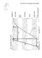
- the difference between the measured individual loudness curve and the standard loudness curve of the normal hearing person i.e. the difference in input level necessary for obtaining the same loudness perception, is considered. This is indicated by arrows D1 and D2 in Fig. 3 .
- the individual loudness curve is interpolated linearly between the measured test input levels.
- Each input level difference D1 and D2 corresponds to the necessary additional gain at the respective input level of the standard loudness curve (which is labeled S in Fig. 3 ).
- the result is shown in Fig. 4 wherein the additional gain relative to the standard gain function necessary for approaching the loudness curve of a normal-hearing person is shown for a given frequency as a function of the input level.
- the gain may be progressively reduced towards low input levels regarding the values obtained from Fig. 3 in order to implement a function which is known as "soft squelch” and which serves to reduce or eliminate microphone noise otherwise occurring at very low input levels.
- the gain may be progressively reduced towards high input levels relative to the gain determined from Fig. 3 in order to implement a "maximum power output” (MPO) function which serves to avoid uncomfortably high loudness values so that the UCL should not be exceeded.
- MPO maximum power output
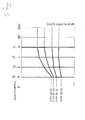
- the obtained data could be represented in an alternative manner as shown in Fig. 5 , wherein the transducer output level is plotted as function of frequency for various input levels. Between the test frequencies f 0 to f 3 the values have been interpolated linearly.
- the transducer output level shown in Fig. 5 corresponds to the preliminary individual gain of the hearing instrument plus the input level.
- the hearing instrument is operated with the preliminary individual gain function determined at the first stage in order to measure at least one contour of equal loudness (however, use of preliminary individual gain function for operating the hearing instrument is not necessary if the stimulus is generated by the sound generator 28).
- the contour of equal loudness is measured at the MCL, for example, at 65 phon.
- narrow-band noise other than pure sinus tones is used as the stimulus.
- the stimulus preferably is provided by the internal sound generator 28 of the control unit 18. In order to determine the contour of equal loudness, for a number of test frequencies the input level of the stimulus is varied until the desired loudness is perceived by the user.
- the test frequencies for the ELC measurements are selected such that the frequency resolution is improved regarding the audiogram measurements of the first stage.
- at least one test frequency of ELC measurement should be located between two of the test frequencies of the first stage.
- two additional test frequencies of the second stage are located between each pair of adjacent test frequencies of the first stage.
- the number of test frequencies of the ELC measurements is higher than the number of test frequencies of the first stage loudness measurements.
- twenty test frequencies are used between 0.125 and 8 kHz.
- the solid line in Fig. 6 shows an example of an ELC of a normal hearing person.
- FIG. 6 represent the difference between the measured ELC and the ELC for the same loudness as estimated from the loudness measurements of the first stage by linear interpolation between the test frequencies of the first stage loudness measurements.
- the arrows of Fig. 6 essentially show the deviation of the actually measured ELC from the linear interpolation.
- the test frequencies of the first and second stage measurements coincide, there may be some deviation, since the first stage loudness measurements were performed with pure sinus tones, while the second stage ELC measurements were performed with narrow-band noise, which different stimuli may cause different loudness perception even for the same input level.
- the ELC measurements include at least five test frequencies between 0.75 and 3 kHz in order to be able to compensate the resonance of the output transducer 32 accurately.
- Fig. 7 is similar to Fig. 5 , with the arrows of Fig. 6 having been added to the 75 dB input level curve (the transducer output level is input level times gain provided by the hearing instrument).
- Fig. 8 is a representation similar to Fig. 7 , wherein the transducer output level curves have been corrected according to the ELC measurement arrows, with the regions between the test frequencies having been interpolated. Since the output transducer resonance is expected to be linear regarding input level, the corrections obtained from this single ELC measurement can be extrapolated linearly to ELC at other loudness values, so that measurement of ELC for one single loudness is sufficient. This is how the corrected curves at input levels other than 75 dB of Fig. 8 are obtained.
- the corrected individual gain function can be determined, since the gain function is the ratio of the transducer output level to the input level.
- the hearing instrument is operated with the corrected individual gain function obtained by the above-described fitting procedure.
Landscapes
- Health & Medical Sciences (AREA)
- General Health & Medical Sciences (AREA)
- Neurosurgery (AREA)
- Otolaryngology (AREA)
- Physics & Mathematics (AREA)
- Engineering & Computer Science (AREA)
- Acoustics & Sound (AREA)
- Signal Processing (AREA)
- Circuit For Audible Band Transducer (AREA)
Applications Claiming Priority (1)
| Application Number | Priority Date | Filing Date | Title |
|---|---|---|---|
| EP20060006023 EP1705950B1 (fr) | 2006-03-23 | 2006-03-23 | Procedé pour l'adaptation individuelle d'un appareil auditif |
Related Parent Applications (2)
| Application Number | Title | Priority Date | Filing Date |
|---|---|---|---|
| EP06006023.3 Division | 2006-03-23 | ||
| EP20060006023 Division-Into EP1705950B1 (fr) | 2006-03-23 | 2006-03-23 | Procedé pour l'adaptation individuelle d'un appareil auditif |
Publications (1)
| Publication Number | Publication Date |
|---|---|
| EP2278827A1 true EP2278827A1 (fr) | 2011-01-26 |
Family
ID=36746484
Family Applications (2)
| Application Number | Title | Priority Date | Filing Date |
|---|---|---|---|
| EP20060006023 Expired - Lifetime EP1705950B1 (fr) | 2006-03-23 | 2006-03-23 | Procedé pour l'adaptation individuelle d'un appareil auditif |
| EP10177370A Withdrawn EP2278827A1 (fr) | 2006-03-23 | 2006-03-23 | Procedé pour l'adaptation individuelle d'un appareil auditif |
Family Applications Before (1)
| Application Number | Title | Priority Date | Filing Date |
|---|---|---|---|
| EP20060006023 Expired - Lifetime EP1705950B1 (fr) | 2006-03-23 | 2006-03-23 | Procedé pour l'adaptation individuelle d'un appareil auditif |
Country Status (3)
| Country | Link |
|---|---|
| EP (2) | EP1705950B1 (fr) |
| AU (1) | AU2007229057B2 (fr) |
| WO (1) | WO2007107292A2 (fr) |
Families Citing this family (13)
| Publication number | Priority date | Publication date | Assignee | Title |
|---|---|---|---|---|
| US8452021B2 (en) | 2007-04-17 | 2013-05-28 | Starkey Laboratories, Inc. | Real ear measurement system using thin tube |
| DK2107830T3 (da) | 2008-03-31 | 2014-07-28 | Starkey Lab Inc | Fremgangsmåde og apparat til måling på et faktisk øre til modtageranordninger i øregangen |
| AU2009201228B2 (en) | 2008-03-31 | 2011-09-22 | Starkey Laboratories, Inc. | Real ear measurement adaptor with internal sound conduit |
| US8571224B2 (en) | 2008-08-08 | 2013-10-29 | Starkey Laboratories, Inc. | System for estimating sound pressure levels at the tympanic membrane using pressure-minima based distance |
| US8144909B2 (en) | 2008-08-12 | 2012-03-27 | Cochlear Limited | Customization of bone conduction hearing devices |
| DK2207366T3 (en) | 2009-01-12 | 2014-12-01 | Starkey Lab Inc | SYSTEM FOR DETERMINING THE LEVEL OF SOUND PRESSURE AT eardrum OF USE OF MEASUREMENTS AWAY from the eardrum |
| US9107015B2 (en) * | 2009-03-27 | 2015-08-11 | Starkey Laboratories, Inc. | System for automatic fitting using real ear measurement |
| WO2012127445A2 (fr) | 2011-03-23 | 2012-09-27 | Cochlear Limited | Accessoire de dispositifs auditifs |
| CN103177727B (zh) * | 2011-12-23 | 2015-05-06 | 重庆重邮信科通信技术有限公司 | 一种音频频带处理方法及系统 |
| US9253586B2 (en) * | 2013-04-26 | 2016-02-02 | Sony Corporation | Devices, methods and computer program products for controlling loudness |
| US9807519B2 (en) * | 2013-08-09 | 2017-10-31 | The United States Of America As Represented By The Secretary Of Defense | Method and apparatus for analyzing and visualizing the performance of frequency lowering hearing aids |
| US10842418B2 (en) * | 2014-09-29 | 2020-11-24 | Starkey Laboratories, Inc. | Method and apparatus for tinnitus evaluation with test sound automatically adjusted for loudness |
| SE546602C2 (en) * | 2023-05-08 | 2025-01-02 | Melisono Ab | Dynamic Hearing Restoration Device |
Citations (11)
| Publication number | Priority date | Publication date | Assignee | Title |
|---|---|---|---|---|
| US4099035A (en) * | 1976-07-20 | 1978-07-04 | Paul Yanick | Hearing aid with recruitment compensation |
| DE3205685A1 (de) | 1982-02-17 | 1983-08-25 | Robert Bosch Gmbh, 7000 Stuttgart | Hoergeraet |
| US4577641A (en) | 1983-06-29 | 1986-03-25 | Hochmair Ingeborg | Method of fitting hearing prosthesis to a patient having impaired hearing |
| EP0535425B1 (fr) | 1991-10-03 | 1997-03-19 | Ascom Audiosys Ag | Procédé d'amplification de signaux acoustiques pour les malentendants et dispositif pour la réalisation du procédé |
| WO2000065872A1 (fr) * | 1999-04-26 | 2000-11-02 | Dspfactory Ltd. | Correction physiologique d'une prothese auditive numerique |
| DE19914992A1 (de) | 1999-04-01 | 2000-12-07 | Implex Hear Tech Ag | Implantierbares Hörsystem mit Audiometer |
| US6201875B1 (en) | 1998-03-17 | 2001-03-13 | Sonic Innovations, Inc. | Hearing aid fitting system |
| US6315710B1 (en) | 1997-07-21 | 2001-11-13 | St. Croix Medical, Inc. | Hearing system with middle ear transducer mount |
| DE10041726C1 (de) | 2000-08-25 | 2002-05-23 | Implex Ag Hearing Technology I | Implantierbares Hörsystem mit Mitteln zur Messung der Ankopplungsqualität |
| EP0661905B1 (fr) | 1995-03-13 | 2002-12-11 | Phonak Ag | Procédé d'adaptation de prothèse auditive, dispositif à cet effet et prothèse auditive |
| WO2004054318A1 (fr) | 2002-12-09 | 2004-06-24 | Microsound A/S | Procede d'adaptation d'un dispositif de communication portable a un malentendant |
-
2006
- 2006-03-23 EP EP20060006023 patent/EP1705950B1/fr not_active Expired - Lifetime
- 2006-03-23 EP EP10177370A patent/EP2278827A1/fr not_active Withdrawn
-
2007
- 2007-03-15 WO PCT/EP2007/002303 patent/WO2007107292A2/fr not_active Ceased
- 2007-03-15 AU AU2007229057A patent/AU2007229057B2/en not_active Ceased
Patent Citations (13)
| Publication number | Priority date | Publication date | Assignee | Title |
|---|---|---|---|---|
| US4099035A (en) * | 1976-07-20 | 1978-07-04 | Paul Yanick | Hearing aid with recruitment compensation |
| DE3205685A1 (de) | 1982-02-17 | 1983-08-25 | Robert Bosch Gmbh, 7000 Stuttgart | Hoergeraet |
| US4577641A (en) | 1983-06-29 | 1986-03-25 | Hochmair Ingeborg | Method of fitting hearing prosthesis to a patient having impaired hearing |
| EP0535425B1 (fr) | 1991-10-03 | 1997-03-19 | Ascom Audiosys Ag | Procédé d'amplification de signaux acoustiques pour les malentendants et dispositif pour la réalisation du procédé |
| EP0661905B1 (fr) | 1995-03-13 | 2002-12-11 | Phonak Ag | Procédé d'adaptation de prothèse auditive, dispositif à cet effet et prothèse auditive |
| US6315710B1 (en) | 1997-07-21 | 2001-11-13 | St. Croix Medical, Inc. | Hearing system with middle ear transducer mount |
| US6201875B1 (en) | 1998-03-17 | 2001-03-13 | Sonic Innovations, Inc. | Hearing aid fitting system |
| US6574342B1 (en) | 1998-03-17 | 2003-06-03 | Sonic Innovations, Inc. | Hearing aid fitting system |
| DE19914992A1 (de) | 1999-04-01 | 2000-12-07 | Implex Hear Tech Ag | Implantierbares Hörsystem mit Audiometer |
| WO2000065872A1 (fr) * | 1999-04-26 | 2000-11-02 | Dspfactory Ltd. | Correction physiologique d'une prothese auditive numerique |
| DE10041726C1 (de) | 2000-08-25 | 2002-05-23 | Implex Ag Hearing Technology I | Implantierbares Hörsystem mit Mitteln zur Messung der Ankopplungsqualität |
| US6554762B2 (en) | 2000-08-25 | 2003-04-29 | Cochlear Limited | Implantable hearing system with means for measuring its coupling quality |
| WO2004054318A1 (fr) | 2002-12-09 | 2004-06-24 | Microsound A/S | Procede d'adaptation d'un dispositif de communication portable a un malentendant |
Also Published As
| Publication number | Publication date |
|---|---|
| WO2007107292A3 (fr) | 2007-11-01 |
| EP1705950A3 (fr) | 2007-01-24 |
| AU2007229057B2 (en) | 2010-11-25 |
| EP1705950A2 (fr) | 2006-09-27 |
| EP1705950B1 (fr) | 2014-08-06 |
| AU2007229057A1 (en) | 2007-09-27 |
| WO2007107292A2 (fr) | 2007-09-27 |
Similar Documents
| Publication | Publication Date | Title |
|---|---|---|
| AU2007229057B2 (en) | Method for individually fitting a hearing instrument | |
| US7715571B2 (en) | Method for individually fitting a hearing instrument | |
| AU2008229850B2 (en) | Method for fitting a bone anchored hearing aid to a user and bone anchored bone conduction hearing aid system | |
| AU2001268142B2 (en) | Method and apparatus for measuring the performance of an implantable middle ear hearing aid, and the response of patient wearing such a hearing aid | |
| US7068793B2 (en) | Method of automatically fitting hearing aid | |
| EP2314079B1 (fr) | Personnalisation de dispositifs auditifs ancrés dans l'os | |
| US9955270B2 (en) | Bone conduction device fitting | |
| AU2001268142A1 (en) | Method and apparatus for measuring the performance of an implantable middle ear hearing aid, and the response of patient wearing such a hearing aid | |
| US10798504B2 (en) | Bimodal hearing stimulation system and method of fitting the same | |
| EP2726017B1 (fr) | Procédé et système de configuration d'un dispositif médical stimulant le système physiologique chez l'homme | |
| EP3113519B1 (fr) | Procédés et dispositifs pour placement correct et sûr d'un dispositif de communication intra-auriculaire dans le canal auditif d'un utilisateur | |
| EP3000398A1 (fr) | Procédé et appareil pour l'évaluation d'acouphène avec son de test à volume ajusté automatiquement |
Legal Events
| Date | Code | Title | Description |
|---|---|---|---|
| PUAI | Public reference made under article 153(3) epc to a published international application that has entered the european phase |
Free format text: ORIGINAL CODE: 0009012 |
|
| AC | Divisional application: reference to earlier application |
Ref document number: 1705950 Country of ref document: EP Kind code of ref document: P |
|
| AK | Designated contracting states |
Kind code of ref document: A1 Designated state(s): AT BE BG CH CY CZ DE DK EE ES FI FR GB GR HU IE IS IT LI LT LU LV MC NL PL PT RO SE SI SK TR |
|
| 17P | Request for examination filed |
Effective date: 20110726 |
|
| 17Q | First examination report despatched |
Effective date: 20140129 |
|
| 17Q | First examination report despatched |
Effective date: 20140205 |
|
| 17Q | First examination report despatched |
Effective date: 20140214 |
|
| 17Q | First examination report despatched |
Effective date: 20140220 |
|
| 17Q | First examination report despatched |
Effective date: 20140226 |
|
| 17Q | First examination report despatched |
Effective date: 20140306 |
|
| 17Q | First examination report despatched |
Effective date: 20140319 |
|
| STAA | Information on the status of an ep patent application or granted ep patent |
Free format text: STATUS: THE APPLICATION IS DEEMED TO BE WITHDRAWN |
|
| 18D | Application deemed to be withdrawn |
Effective date: 20140730 |