EP2278862A2 - Dispositif d'éclairage de lampe à décharge haute pression, et appareil d'éclairage et système d'éclairage l'utilisant - Google Patents
Dispositif d'éclairage de lampe à décharge haute pression, et appareil d'éclairage et système d'éclairage l'utilisant Download PDFInfo
- Publication number
- EP2278862A2 EP2278862A2 EP10007616A EP10007616A EP2278862A2 EP 2278862 A2 EP2278862 A2 EP 2278862A2 EP 10007616 A EP10007616 A EP 10007616A EP 10007616 A EP10007616 A EP 10007616A EP 2278862 A2 EP2278862 A2 EP 2278862A2
- Authority
- EP
- European Patent Office
- Prior art keywords
- phase
- discharge lamp
- pressure discharge
- lighting device
- circuit
- Prior art date
- Legal status (The legal status is an assumption and is not a legal conclusion. Google has not performed a legal analysis and makes no representation as to the accuracy of the status listed.)
- Granted
Links
- 238000005286 illumination Methods 0.000 title claims description 15
- 230000015556 catabolic process Effects 0.000 claims abstract description 34
- 238000010438 heat treatment Methods 0.000 claims abstract description 11
- 230000010363 phase shift Effects 0.000 claims description 14
- 238000006243 chemical reaction Methods 0.000 claims description 9
- 238000010891 electric arc Methods 0.000 abstract description 15
- 238000001514 detection method Methods 0.000 abstract description 11
- 239000003990 capacitor Substances 0.000 description 20
- 238000010586 diagram Methods 0.000 description 7
- 238000009499 grossing Methods 0.000 description 5
- 230000000694 effects Effects 0.000 description 4
- 230000006872 improvement Effects 0.000 description 4
- 238000004804 winding Methods 0.000 description 4
- 238000000034 method Methods 0.000 description 3
- 230000008569 process Effects 0.000 description 3
- 230000001172 regenerating effect Effects 0.000 description 3
- QSHDDOUJBYECFT-UHFFFAOYSA-N mercury Chemical compound [Hg] QSHDDOUJBYECFT-UHFFFAOYSA-N 0.000 description 2
- 229910052753 mercury Inorganic materials 0.000 description 2
- 229910001507 metal halide Inorganic materials 0.000 description 2
- 150000005309 metal halides Chemical class 0.000 description 2
- 230000008859 change Effects 0.000 description 1
- 238000007796 conventional method Methods 0.000 description 1
- 230000001788 irregular Effects 0.000 description 1
- 238000012544 monitoring process Methods 0.000 description 1
- 230000009467 reduction Effects 0.000 description 1
- 230000004044 response Effects 0.000 description 1
- 230000007704 transition Effects 0.000 description 1
Images






Classifications
-
- H—ELECTRICITY
- H05—ELECTRIC TECHNIQUES NOT OTHERWISE PROVIDED FOR
- H05B—ELECTRIC HEATING; ELECTRIC LIGHT SOURCES NOT OTHERWISE PROVIDED FOR; CIRCUIT ARRANGEMENTS FOR ELECTRIC LIGHT SOURCES, IN GENERAL
- H05B41/00—Circuit arrangements or apparatus for igniting or operating discharge lamps
- H05B41/14—Circuit arrangements
- H05B41/26—Circuit arrangements in which the lamp is fed by power derived from DC by means of a converter, e.g. by high-voltage DC
- H05B41/28—Circuit arrangements in which the lamp is fed by power derived from DC by means of a converter, e.g. by high-voltage DC using static converters
- H05B41/288—Circuit arrangements in which the lamp is fed by power derived from DC by means of a converter, e.g. by high-voltage DC using static converters with semiconductor devices and specially adapted for lamps without preheating electrodes, e.g. for high-intensity discharge lamps, high-pressure mercury or sodium lamps or low-pressure sodium lamps
- H05B41/2885—Static converters especially adapted therefor; Control thereof
- H05B41/2886—Static converters especially adapted therefor; Control thereof comprising a controllable preconditioner, e.g. a booster
-
- H—ELECTRICITY
- H05—ELECTRIC TECHNIQUES NOT OTHERWISE PROVIDED FOR
- H05B—ELECTRIC HEATING; ELECTRIC LIGHT SOURCES NOT OTHERWISE PROVIDED FOR; CIRCUIT ARRANGEMENTS FOR ELECTRIC LIGHT SOURCES, IN GENERAL
- H05B41/00—Circuit arrangements or apparatus for igniting or operating discharge lamps
- H05B41/14—Circuit arrangements
- H05B41/26—Circuit arrangements in which the lamp is fed by power derived from DC by means of a converter, e.g. by high-voltage DC
- H05B41/28—Circuit arrangements in which the lamp is fed by power derived from DC by means of a converter, e.g. by high-voltage DC using static converters
- H05B41/288—Circuit arrangements in which the lamp is fed by power derived from DC by means of a converter, e.g. by high-voltage DC using static converters with semiconductor devices and specially adapted for lamps without preheating electrodes, e.g. for high-intensity discharge lamps, high-pressure mercury or sodium lamps or low-pressure sodium lamps
- H05B41/2885—Static converters especially adapted therefor; Control thereof
- H05B41/2887—Static converters especially adapted therefor; Control thereof characterised by a controllable bridge in the final stage
Definitions
- the present invention relates to a high pressure discharge lamp lighting device for a lighting high-intensity high-pressure discharge lamp such as a high-pressure mercury lamp and a metal halide lamp, and an illumination fixture and an illumination system which use the high pressure discharge lamp lighting device.
- a lighting high-intensity high-pressure discharge lamp such as a high-pressure mercury lamp and a metal halide lamp
- an illumination fixture and an illumination system which use the high pressure discharge lamp lighting device.
- Fig. 10 shows a conventional example of an electronic high pressure discharge lamp lighting device.
- a lighting circuit 1 is formed of a full-wave rectifying circuit DB, a step-up chopper circuit 11 and a polarity inverting step-down chopper circuit 12.
- the polarity inverting step-down chopper circuit 12 is configured by connecting an inductor L2 in series with a load and a capacitor C3 in parallel with the load to outputs of a full bridge circuit formed of switching elements Q3 to Q6.
- the switching elements Q3 to Q6 are controlled by a switching element control circuit 4 and operate so as to become a high-frequency output at starting and a low-frequency rectangular output by a step-down chopper operation at lighting.
- a starting circuit 2 is formed of a resonance step-up circuit inserted between an output of the lighting circuit 1 and a high-pressure discharge lamp DL.
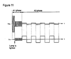
- Fig. 11 schematically shows an operational waveform in a first conventional example.
- V1a refers to a lamp voltage applied to both ends of the high-pressure discharge lamp DL
- I1a refers to a lamp current flowing to the high-pressure discharge lamp DL.
- a high-frequency high voltage is applied to the high-pressure discharge lamp DL by a resonance step-up effect of the starting circuit 2.
- the lamp current I1a starts to flow.
- the flowing lamp current I1a is a current with a small amplitude.
- the electrodes are heated.
- the A1 phase for a predetermined period shifts to an A3 phase as a stable lighting period
- a low-frequency rectangular wave voltage is applied to the high-pressure discharge lamp DL.
- Fig. 12 shows the operational waveform in first conventional example in detail.
- the starting circuit 2 formed of the resonance step-up circuit generates a high-frequency high voltage, thereby leading to the electric breakdown between the electrodes of the high-pressure discharge lamp DL.
- an operational frequency fa1 remains the same as before the electric breakdown and the amplitude of the lamp current I1a is small.
- the switching elements Q3, Q4 are alternately turned on/off with a low frequency. Then, by a polarity inverting step-down chopper operation of turning on/off the switching element Q6 with a high frequency during the switching element Q3 is turned on and turning on/off the switching element Q5 with a high frequency during the switching element Q4 is turned on, a low-frequency rectangular wave AC voltage is supplied to the high-pressure discharge lamp DL.
- an output detection part 3 detects the lamp voltage V1a and in response to the detection signal, the switching element control circuit 4 controls an ON duration of the chopper operation of the switching elements Q5, Q6 so as to result in an appropriate lamp current I1a.
- a DC power source Vdc is converted into a rectangular wave AC voltage which is necessary for stable lighting of the high-pressure discharge lamp DL and the AC voltage is applied to the high-pressure discharge lamp La.
- a high voltage is generated from starting to stable lighting of the high-pressure discharge lamp DL, thereby switching between the A1 phase as an ignition phase for generating the electric breakdown between the electrodes and the A3 phase as a running phase for maintaining arc discharge.
- Patent Document 1 (Unexamined Patent Publication No. 2005-507553 ) proposes that a warm-up phase (A2 phase) for transferring the ignition phase (A1 phase) for generating the electric breakdown between the electrodes to the running phase (A3 phase) for maintaining arc discharge is inserted.
- Fig. 13 shows transition of the lamp voltage V1a and an operational frequency f after power-on in a control example disclosed in Patent Document1.
- 0 to t2 refers to the A1 phase
- t2 to t3 refers to the A2 phase and t3 and thereafter refers to the A3 phase.
- the control example disclosed in Patent Document 1 when the operational frequency is gradually lowered after power-on and reaches a frequency which is one third of the resonance frequency fo of a resonance circuit (fo/3) at the time t1, the frequency is fixed and a high-frequency generating operation using a resonance effect is maintained up to the time t2.
- the operational frequency is lowered in a stepped manner.
- the lamp current 11a can be increased as the operational frequency f lowers and thus, the electrodes of the high-pressure discharge lamp can be sufficiently heated.
- the same operation as in the first conventional example is performed at the time t3 and thereafter, since the electrodes are sufficiently heated, go-out is hard to occur.
- Patent Document 1 Japanese Translation of PCT No. 2005-507553 ( Fig. 3, Fig. 4 )
- First conventional example has the following problems. As shown in Fig. 11 and Fig. 12 , it is desired that when the high-pressure discharge lamp is lighted in the A1 phase, the high-pressure discharge lamp shifts from glow discharge to arc discharge in the remaining A1 phase. However, since an amplitude of the current is small, the A1 phase shifts to the A3 phase before the electrodes of the high-pressure discharge lamp are sufficiently heated. As a result, go-out easily occurs and the discharge lamp may be in an unlighted state.
- timing of the electric breakdown of the high-pressure discharge lamp varies depending on the state of the high-pressure discharge lamp, a remaining electrode heating time in the A1 phase after the electric breakdown also becomes irregular, and disadvantageously, the high-pressure discharge lamp easily goes out at a timing when the polarity of the high-pressure discharge lamp is inverted in the A3 phase.
- the A2 phase uselessly exists and therefore, a starting time of the high-pressure discharge lamp becomes longer.
- a high voltage though lower than the voltage in the A1 phase, is generated in the A2 phase in which the discharge lamp is not lighted, an excess stress is exerted on parts.
- an object of the present invention is to provide a high pressure discharge lamp lighting device which can determine lighting of the high-pressure discharge lamp before shifting from the starting state to the normal lighted state, insert an operating period for heating the electrodes and sufficiently heat the electrodes of the high-pressure discharge lamp when it is determined that the high-pressure discharge lamp is in the lighted state, thereby shifting the lamp to the normal lighted state in a stable arc discharge state.
- a high pressure discharge lamp lighting device having a DC power source (step-up chopper circuit 11), a power conversion circuit (polarity inverting step-down shopper circuit 12) for converting an output voltage Vdc of the DC power source into electric power required for a high-pressure discharge lamp DL to stably light the high-pressure discharge lamp DL, a starting circuit 2 for generating a high voltage to start the high-pressure discharge lamp DL, a power conversion control circuit (switching element control circuit 4) for controlling the power conversion circuit from starting to stable lighting of the high-pressure discharge lamp DL and a lighting determination circuit (output detection part 3) for determining a lighted state of the high-pressure discharge lamp DL, wherein the power conversion control circuit, as shown in Fig.
- the lighting determination circuit (output detection part 3) performs a lighting determination operation at a timing before shifting to the third phase A3 and when it is determined that the lamp is lighted, the second phase A2 is inserted.
- the operation in the third phase is a low-frequency rectangular wave operation.
- the lighting determination timing is in the first phase.
- the first phase is a high-frequency operation period.
- the lighting determination timing exists after termination of the first phase ( Fig. 5 , Fig. 6 ).
- the lighting determination timing after termination of the first phase is in a low-frequency operation period.
- the low-frequency operation period is at least a half cycle or longer.
- polarity of the high-pressure discharge lamp to determine whether or not it is lighted is the same polarity ( Fig. 5 ).
- the polarity of the high-pressure discharge lamp to determine whether or not it is lighted is both polarities ( Fig. 6 ).
- the first phase shifts to a phase other than the second phase ( Fig. 4 , Fig. 6 ).
- the shift destination other than the second phase is the first phase.
- the shift destination other than the second phase is a pause phase ( Fig. 4 , Fig. 6 ).
- a thirteenth aspect of the present invention is an illumination fixture including the high pressure discharge lamp lighting device according to any of the first to twelfth aspects of the present invention ( Fig. 9 ).
- a fourteenth aspect of the present invention is an illumination system including the illumination fixture according to the thirteenth aspect of the present invention.
- the lamp when the electric breakdown occurs between the electrodes of the high-pressure discharge lamp in the first phase, the lamp can be reliably lighted by heating the electrodes in the second phase and go-out is not repeated. Thus, longer life of the high-pressure discharge lamp can be achieved.
- the electric breakdown does not occur between the electrodes of the high-pressure discharge lamp in the first phase, the operation in the second phase is not uselessly inserted and therefore, the starting time can be shortened.
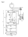
- Fig. 1 is a circuit diagram in a first embodiment of the present invention.
- a basic configuration is the same as that in the conventional example shown in Fig. 10 except that the switching element control circuit 4 includes an A2 phase shift control circuit 5.
- a circuit configuration in Fig. 1 will be described in detail.
- the full-wave rectifying circuit DB is a diode bridge circuit which is connected to a commercial AC power source Vs, rectifies an AC voltage of the AC power source and outputs an undulating voltage.
- a filter circuit for preventing leakage of high frequency may be provided at an AC input terminal of the full-wave rectifying circuit DB.
- the step-up chopper circuit 11 receives an input of the voltage rectified by the full-wave rectifying circuit DB and outputs a boosted DC voltage Vdc.
- An input capacitor C1 is parallely connected to an output terminal of the full-wave rectifying circuit DB and a series circuit formed of the inductor L1 and the switching element Q1 is connected to the output terminal of the full-wave rectifying circuit DB, and a smoothing capacitor C2 is connected between both ends of the switching element Q1 through a diode D1.
- an output voltage of the full-wave rectifying circuit DB is boosted to the defined DC voltage Vdc and charged to the smoothing capacitor C2, and power factor improvement control to give resistance to the circuit is performed so that an input current and an input voltage from the commercial AC power source Vs may not be out of phase with each other.
- the polarity inverting step-down chopper circuit 12 is configured by connecting a filter circuit formed of an inductor L2 in series with a load and a capacitor C3 in parallel with the load to an output of a full bridge circuit formed of the switching elements Q3 to Q6.
- the high-pressure discharge lamp DL as the load is a high-intensity high-pressure discharge lamp (HID lamp) such as a metal halide lamp and a high-pressure mercury lamp.
- the switching elements Q3 to Q6 of the polarity inverting step-down chopper circuit 12 are controlled by the switching element control circuit 4. The operation is shown in Fig. 2 .
- an A1 phase is an electric breakdown period (ignition phase)
- an A2 phase is a shift period from glow discharge to arc discharge after the electric breakdown (warm-up phase)
- an A3 phase is a stable lighting period (running phase).
- Fig. 2 shows an on/off operation of the switching elements Q3 to Q6, and the lamp voltage V1a and the lamp current I1a of the high-pressure discharge lamp DL in each phase.
- Controls in the A1 to A3 phases shown in Fig. 2 are sequentially performed by using the high pressure discharge lamp lighting device shown in Fig. 1 until the high-pressure discharge lamp DL shifts from an unlighted state to a stable lighted state.
- a starting high voltage is supplied to the high-pressure discharge lamp DL.
- the frequency fa1 is swept around the resonance frequency fo of a primary winding n1 of a pulse transformer PT and the capacitor C2 in the starting circuit 2 or an integral submultiple of a resonance frequency fo (for example, fo/3).
- a resonance voltage generated at a primary winding n1 of the pulse transformer PT is boosted through a secondary winding n2 at a winding ratio of nl:n2 and the boosted voltage is applied between the electrodes of the high-pressure discharge lamp DL through the capacitor C3, thereby causing the electric breakdown between the electrodes.
- the switching element control circuit 4 for controlling the switching elements Q3 to Q6 of the polarity inverting step-down chopper circuit 12 includes the A2 phase shift control circuit 5 for controlling shift from the A1 phase to the A2 phase, and in the present embodiment, when it is determined that the high-pressure discharge lamp DL is lighted according to the detection signal of the output detection part 3 which operates in the A1 phase at all times, the A1 phase shifts to the A2 phase. Accordingly, the A1 phase in the present embodiment also functions as a lighting determination phase.
- the output detection part 3 can determine the lighted state of the high-pressure discharge lamp DL.
- the lamp current I1a flowing to the high-pressure discharge lamp DL may be detected.
- the frequency fa2 is set to be lower than the frequency fa1 in the A1 phase.
- the lamp current I1a in the A1 phase, the lamp current I1a does not flow and an amplitude of the lamp voltage V1a is high, while in the A2 phase, the lamp current I1a starts to flow and the amplitude of the lamp voltage V1a is lower than that in the A1 phase.
- the high-pressure discharge lamp DL starts glow discharge.
- a DC output of the step-up chopper circuit 11 is converted into a lowered low-frequency rectangular wave AC voltage and the converted voltage is applied to the high-pressure discharge lamp DL.
- the polarity inverting step-down chopper circuit 12 alternately turns on/off the switching elements Q3, Q4 with a predetermined low frequency fa3 (a few dozens of Hz to a few hundreds of Hz), and at this time, an operation of turning on/off the switching element Q6 with a predetermined frequency (a few dozens of kHz) while the switching element Q3 is turned on and turning on/off the switching element Q5 with a predetermined frequency (a few dozens of kHz) while the switching element Q4 is turned on is repeated.
- the capacitor C3 and the inductor L2 function as a filter circuit of a step-down chopper circuit and an antiparallel diode (body diode) built in the switching elements Q5, Q6 functions as a regenerative current energization diode of the step-down chopper circuit.
- the lamp voltage V1a of the high-pressure discharge lamp DL gradually rises from a few volts to a rated voltage (a few dozens of volts to a few hundreds of volts) in a few minutes.
- a rated voltage a few dozens of volts to a few hundreds of volts
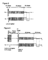
- Figs. 3 and 4 show operation in the case where the electric breakdown occurs in the high-pressure discharge lamp DL in the first A1 phase after power-on and operation in the case where the electric breakdown does not occur in the high-pressure discharge lamp DL in the first A1 phase after power-on and occurs in a second A1 phase, respectively.
- FIG. 3 shows relationship between the lamp voltage V1a and the lamp current I1a of the high-pressure discharge lamp DL in a starting process in which the electric breakdown occurs in the high-pressure discharge lamp DL in the first A1 phase, and the A1 phase shifts to the A2 phase and the A3 phase.
- a starting high voltage is applied between the electrodes of the high-pressure discharge lamp DL, thereby causing the electric breakdown.
- Fig. 4 shows relationship between the lamp voltage V1a and the lamp current I1a of the high-pressure discharge lamp DL in a starting process in which the electric breakdown does not occur in the high-pressure discharge lamp DL in the first A1 phase after power-on and occurs in the second A1 phase, and then, the A1 phase shifts to the A2 phase and the A3 phase.
- the A1 phase shifts to a pause phase for a certain time and then, proceeds to the second A1 phase.
- a predetermined time predetermined upper limit of duration of the A1 phase
- the A1 phase immediately shifts to the A2 phase to uniformly and sufficiently raise temperature of both electrodes of the high-pressure discharge lamp DL and put the lamp into the stable arc discharge state, and then, the phase is lead to the A3 phase.
- the A1 phase may be restarted without shifting to the pause phase, thereby causing the electric breakdown in the high-pressure discharge lamp DL.
- the A1 phase can rapidly shift to the A2 phase for heating the both electrodes of the high-pressure discharge lamp DL before the previously set duration of the A1 phase has passed, so that the starting time can be shortened.
- the high-pressure discharge lamp DL is not lighted in the A1 phase, since the A1 phase shifts to the pause phase without uselessly spending time equivalent to the A2 phase, the starting time can be shortened, resulting in improvement of startability of the high-pressure discharge lamp.
- the A1 phase since lighting/unlighting of the high-pressure discharge lamp DL is determined in the A1 phase, when the electric breakdown occurs in the high-pressure discharge lamp DL in the A1 phase for the predetermined time, the A1 phase can immediately shift to the A2 phase, and conversely when the electric breakdown does not occur in the high-pressure discharge lamp DL in the A1 phase for the predetermined time, the A1 phase can shift to the pause phase by omitting the useless A2 phase.
- the operation in the A1 phase is the high-frequency operation of generating the resonance voltage in the present embodiment
- the operation may be operation obtained by superimposing a pulse voltage on a DC operation or a low-frequency operation.
- the operation in the A2 phase is also the high-frequency operation in the present embodiment
- the operation may be the DC operation or the low-frequency operation.
- the operation in the A3 phase is the low-frequency rectangular wave operation, the operation may be the DC operation or the high-frequency operation as long as the high-pressure discharge lamp is stably lighted.
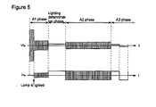
- Fig. 5 is a waveform chart for describing operation in a second embodiment of the present invention.
- a circuit configuration may be the same as that in Fig. 1 .
- Fig. 5 shows relationship between the lamp voltage V1a and the lamp current I1a of the high-pressure discharge lamp DL in a starting process in which, after the electric breakdown occurs in the high-pressure discharge lamp DL in the A1 phase after power-on, through the lighting determination phase for a predetermined time, the A1 phase shifts to the A2 phase and the A3 phase.
- the A1 phase also acts as the lighting determination phase in the first embodiment, while a certain time after termination of the A1 phase for the predetermined time is the lighting determination phase in the second embodiment.
- a certain time after termination of the A1 phase for the predetermined time is the lighting determination phase in the second embodiment.
- the lighting determination phase can be made a preliminary heating phase prior to shift to the A2 phase, resulting in further improvement of startability.
- the operation performed in the lighting determination phase is the DC operation in the present embodiment, it may be a low-frequency rectangular wave operation using DC operations for determining the lighted state of the high-pressure discharge lamp DL at both positive and negative polarities in respective half cycles.
- the lighting determination phase (DC operation) in Fig. 5 is replaced with the low-frequency rectangular wave operation.
- Fig. 6 is a waveform chart for describing operation in a third embodiment of the present invention.
- a circuit configuration may be the same as that in Fig. 1 .
- the third embodiment is characterized in that the polarity of the high-pressure discharge lamp DL is alternately determined in the lighting determination phase (DC operation) shown in the second embodiment.
- DC operation the lighting determination phase
- the A1 phase proceeds to a second A1 phase through a predetermined pause phase.
- the lamp current I1a is detected in the second lighting determination phase (DC operation in which the lamp voltage V1a has the negative polarity)
- the A1 phase shifts to the A2 phase.
- startability is improved by shifting to the A2 phase from not only the same polarity but also the polarity at which the high-pressure discharge lamp is easily lighted.
- the output detection part 3 for determining lighting/unlighting of the high-pressure discharge lamp DL may be a circuit for determining the lamp voltage V1a or a characteristic relating to the lamp voltage V1a, or a circuit for determining the lamp current I1a or a characteristic relating to the lamp current I1a.
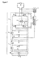
- Fig. 7 is a circuit diagram in a fourth embodiment of the present invention.
- a function of the polarity inverting step-down chopper circuit 12 in Fig. 1 is obtained by combination of the step-down chopper circuit 13 and a polarity inversion circuit 14.
- the step-down chopper circuit 13 functions as a ballast (power conversion circuit) for supplying a target power to the high-pressure discharge lamp DL as the load.
- An output voltage of the step-down chopper circuit 13 is variably controlled by the switching element control circuit 4 so that appropriate power is supplied to the high-pressure discharge lamp DL from starting to the stable lighting period through the arc discharge shift period.
- a circuit configuration of the step-down chopper circuit 13 will be described.
- a positive electrode of the smoothing capacitor C2 as the DC power source is connected to a positive electrode of the capacitor C3 through the switching element Q2 and the inductor L2, and a negative electrode of the capacitor C3 is connected to a negative electrode of the smoothing capacitor C2.
- An anode of a regenerative current energization diode D2 is connected to the negative electrode of the capacitor C3, and a cathode of the diode D2 is connected to a connection point of the switching element Q2 and the inductor L2.
- the switching element Q2 is turned on/off with a high frequency by the output of the switching element control circuit 4, a current flows from the smoothing capacitor C2 as the DC power source through the switching element Q2, the inductor L2 and the capacitor C3 while the switching element Q2 is turned on and a regenerative current flows through the inductor L2, the capacitor C3 and the diode D2 while the switching element Q2 is turned off.
- a DC voltage obtained by lowering the DC voltage Vdc is charged to the capacitor C3.
- the voltage obtained by the capacitor C3 can be variably controlled by varying an ON duty (ratio of an ON time in one cycle) of the switching element Q2.
- the polarity inversion circuit 14 is connected to an output of the step-down chopper circuit 13.
- the polarity inversion circuit 14 is a full bridge circuit formed of the switching elements Q3 to Q6, and a pair of the switching elements Q3, Q6 and a pair of the switching elements Q4, Q5 are alternately turned on with a high frequency at starting and with a low frequency at lighting according to a control signal from the switching element control circuit 4, thereby converting output power of the step-down chopper circuit 13 into rectangular wave AC power and supplying the converted power to the high-pressure discharge lamp DL.
- the operational waveform in the present embodiment is the same as that in Fig. 2 only except that the operation of the switching elements Q5, Q6 in the A3 phase is not the high-frequency operation but the low-frequency operation in sync with the switching elements Q4, Q3.
- the A1 phase and the A2 phase are the same as those in Fig. 2 .
- Fig. 8 is a circuit diagram in a fifth embodiment of the present invention.
- the present embodiment is characterized in that , in the polarity inverting step-down chopper circuit 12 shown in Fig. 1 , the switching elements Q5, Q6 are replaced with capacitors C5, C6 and a half bridge circuit 15 is used in place of the full bridge circuit.
- the operational waveform in the present embodiment is different from that in Fig. 2 in that control signals for the switching elements Q5, Q6 are used as control signals for the switching elements Q3, Q4 in Fig. 8 and a switching frequency of the step-down chopper operation is set to a frequency which does not resonate the starting circuit 2 in the A3 phase.
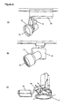
- Fig. 9 shows configuration examples of illumination fixtures using the high pressure discharge lamp lighting device of the present invention.
- DL refers to the high-pressure discharge lamp
- 16 refers to a ballast which stores a circuit of the lighting device
- 17 refers to a lamp body to which the high-pressure discharge lamp DL is attached
- 18 refers to a wire.
- Figs. 9(a) , (b) show an example in which the high-pressure discharge lamp is used as a spotlight
- Fig. 9(c) shows an example in which the high-pressure discharge lamp is used as a downright.
- the lighted high-pressure discharge lamp can be reliably put into an arc discharge state and even in the unlighted high-pressure discharge lamp, the starting time can be shortened as much as possible, resulting in improvement of startability of the high-pressure discharge lamp.
- a plurality of such illumination fixture may be combined to each other to configure an illumination system.
Landscapes
- Circuit Arrangements For Discharge Lamps (AREA)
Applications Claiming Priority (1)
| Application Number | Priority Date | Filing Date | Title |
|---|---|---|---|
| JP2009173692A JP2011029002A (ja) | 2009-07-24 | 2009-07-24 | 高圧放電灯点灯装置及びこれを用いた照明器具、照明システム |
Publications (3)
| Publication Number | Publication Date |
|---|---|
| EP2278862A2 true EP2278862A2 (fr) | 2011-01-26 |
| EP2278862A3 EP2278862A3 (fr) | 2014-06-25 |
| EP2278862B1 EP2278862B1 (fr) | 2019-04-10 |
Family
ID=43242904
Family Applications (1)
| Application Number | Title | Priority Date | Filing Date |
|---|---|---|---|
| EP10007616.5A Not-in-force EP2278862B1 (fr) | 2009-07-24 | 2010-07-22 | Dispositif d'éclairage de lampe à décharge haute pression, et appareil d'éclairage et système d'éclairage l'utilisant |
Country Status (4)
| Country | Link |
|---|---|
| US (1) | US8319447B2 (fr) |
| EP (1) | EP2278862B1 (fr) |
| JP (1) | JP2011029002A (fr) |
| CN (1) | CN101965090A (fr) |
Families Citing this family (8)
| Publication number | Priority date | Publication date | Assignee | Title |
|---|---|---|---|---|
| JP2008187821A (ja) * | 2007-01-30 | 2008-08-14 | Matsushita Electric Works Ltd | 絶縁型ac−dcコンバータおよびそれを用いるled用直流電源装置 |
| CN101404446B (zh) * | 2008-11-11 | 2011-02-16 | 珠海格力电器股份有限公司 | 单周期功率因数校正方法 |
| EP2688140A3 (fr) * | 2012-07-18 | 2014-04-30 | Aisin Seiki Kabushiki Kaisha | Appareil d'entraînement d'antenne |
| JP6244806B2 (ja) * | 2013-10-17 | 2017-12-13 | セイコーエプソン株式会社 | 放電ランプ点灯装置、放電ランプ点灯方法及びプロジェクター |
| CN104682720A (zh) * | 2013-11-29 | 2015-06-03 | 东林科技股份有限公司 | 交交流电源转换装置及其转换方法 |
| JP2015188299A (ja) * | 2014-03-11 | 2015-10-29 | パナソニックIpマネジメント株式会社 | 電力変換装置 |
| KR102023534B1 (ko) * | 2015-04-17 | 2019-09-23 | 엘에스산전 주식회사 | 슬레이브 디바이스 및 이의 제어 방법 |
| JP7649455B2 (ja) * | 2021-07-12 | 2025-03-21 | ウシオ電機株式会社 | 光源装置、誘電体バリア放電ランプの点灯回路、誘電体バリア放電ランプの点灯方法 |
Citations (1)
| Publication number | Priority date | Publication date | Assignee | Title |
|---|---|---|---|---|
| JP2005507553A (ja) | 2001-10-31 | 2005-03-17 | コーニンクレッカ フィリップス エレクトロニクス エヌ ヴィ | バラスト回路 |
Family Cites Families (6)
| Publication number | Priority date | Publication date | Assignee | Title |
|---|---|---|---|---|
| JP3244859B2 (ja) * | 1993-04-12 | 2002-01-07 | 池田デンソー株式会社 | 放電灯点灯装置 |
| JP3207134B2 (ja) * | 1997-05-16 | 2001-09-10 | 株式会社小糸製作所 | 放電灯の点灯回路 |
| US6160362A (en) * | 1998-01-07 | 2000-12-12 | Philips Electronics North America Corporation | Ignition scheme for a high intensity discharge lamp |
| JP3742271B2 (ja) * | 2000-02-25 | 2006-02-01 | 株式会社小糸製作所 | 放電灯点灯回路 |
| JP4940664B2 (ja) * | 2006-01-13 | 2012-05-30 | ウシオ電機株式会社 | 放電ランプ点灯装置およびプロジェクタ |
| JP2008243629A (ja) * | 2007-03-27 | 2008-10-09 | Matsushita Electric Works Ltd | 放電灯点灯装置及び照明器具及び照明システム |
-
2009
- 2009-07-24 JP JP2009173692A patent/JP2011029002A/ja not_active Withdrawn
-
2010
- 2010-07-22 EP EP10007616.5A patent/EP2278862B1/fr not_active Not-in-force
- 2010-07-23 CN CN2010102373395A patent/CN101965090A/zh active Pending
- 2010-07-26 US US12/843,747 patent/US8319447B2/en not_active Expired - Fee Related
Patent Citations (1)
| Publication number | Priority date | Publication date | Assignee | Title |
|---|---|---|---|---|
| JP2005507553A (ja) | 2001-10-31 | 2005-03-17 | コーニンクレッカ フィリップス エレクトロニクス エヌ ヴィ | バラスト回路 |
Also Published As
| Publication number | Publication date |
|---|---|
| US8319447B2 (en) | 2012-11-27 |
| US20110018453A1 (en) | 2011-01-27 |
| JP2011029002A (ja) | 2011-02-10 |
| EP2278862B1 (fr) | 2019-04-10 |
| CN101965090A (zh) | 2011-02-02 |
| EP2278862A3 (fr) | 2014-06-25 |
Similar Documents
| Publication | Publication Date | Title |
|---|---|---|
| EP2278862B1 (fr) | Dispositif d'éclairage de lampe à décharge haute pression, et appareil d'éclairage et système d'éclairage l'utilisant | |
| EP2222142B1 (fr) | Dispositif d'éclairage par lampe à décharge et accessoire d'illumination | |
| CN101652012B (zh) | 高压放电灯点亮装置和照明器具 | |
| WO2008023476A1 (fr) | Lampe à décharge à haute tension, appareil d'éclairage et équipement d'illumination | |
| CA2679816C (fr) | Dispositif d'eclairage de lampe a decharge a haute pression et luminaire y faisant appel | |
| JP2009289492A (ja) | 高圧放電灯点灯装置及び照明器具 | |
| EP2182779B1 (fr) | Dispositif d'éclairage par lampe à décharge et accessoire d'illumination | |
| JP2010198875A (ja) | 放電灯点灯装置及び照明器具 | |
| US8299723B2 (en) | Electronic ballast with lamp flicker suppression during start-to-steady state transition | |
| JP5069573B2 (ja) | 高圧放電灯点灯装置、照明器具 | |
| JP5129652B2 (ja) | 放電灯点灯装置 | |
| JP2010257659A (ja) | 高圧放電灯点灯装置及びそれを用いた照明器具 | |
| EP2339897B1 (fr) | Dispositif d'éclairage d'une lampe de décharge à haute pression et appareil d'éclairage l'utilisant | |
| JP6045858B2 (ja) | 放電灯点灯装置 | |
| JP3846619B2 (ja) | 高圧放電ランプ点灯装置および照明装置 | |
| CN101815393A (zh) | 放电灯照明装置及具有该装置的照明设备 | |
| JP2005259454A (ja) | 放電ランプ点灯装置 | |
| JP2004303688A (ja) | 放電灯点灯装置 | |
| EP2273854A2 (fr) | Dispositif d'éclairage de lampe à décharge haute pression, appareil d'éclairage et système d'éclairage l'utilisant | |
| JP5654852B2 (ja) | 点灯装置及びそれを用いた照明器具 | |
| JP5491716B2 (ja) | 放電灯点灯装置 | |
| JP2010108658A (ja) | 放電灯点灯装置及び照明器具 | |
| JP2012243620A (ja) | 放電灯点灯装置及びそれを用いた照明器具 | |
| JP2009158171A (ja) | 放電ランプ点灯装置および照明器具 | |
| JP2010080243A (ja) | 放電灯点灯装置、前照灯装置、及び車両 |
Legal Events
| Date | Code | Title | Description |
|---|---|---|---|
| PUAI | Public reference made under article 153(3) epc to a published international application that has entered the european phase |
Free format text: ORIGINAL CODE: 0009012 |
|
| AK | Designated contracting states |
Kind code of ref document: A2 Designated state(s): AL AT BE BG CH CY CZ DE DK EE ES FI FR GB GR HR HU IE IS IT LI LT LU LV MC MK MT NL NO PL PT RO SE SI SK SM TR |
|
| AX | Request for extension of the european patent |
Extension state: BA ME RS |
|
| RAP1 | Party data changed (applicant data changed or rights of an application transferred) |
Owner name: PANASONIC CORPORATION |
|
| PUAL | Search report despatched |
Free format text: ORIGINAL CODE: 0009013 |
|
| AK | Designated contracting states |
Kind code of ref document: A3 Designated state(s): AL AT BE BG CH CY CZ DE DK EE ES FI FR GB GR HR HU IE IS IT LI LT LU LV MC MK MT NL NO PL PT RO SE SI SK SM TR |
|
| AX | Request for extension of the european patent |
Extension state: BA ME RS |
|
| RIC1 | Information provided on ipc code assigned before grant |
Ipc: H05B 41/288 20060101AFI20140516BHEP |
|
| 17P | Request for examination filed |
Effective date: 20140724 |
|
| RBV | Designated contracting states (corrected) |
Designated state(s): AL AT BE BG CH CY CZ DE DK EE ES FI FR GB GR HR HU IE IS IT LI LT LU LV MC MK MT NL NO PL PT RO SE SI SK SM TR |
|
| RAP1 | Party data changed (applicant data changed or rights of an application transferred) |
Owner name: PANASONIC INTELLECTUAL PROPERTY MANAGEMENT CO., LT |
|
| STAA | Information on the status of an ep patent application or granted ep patent |
Free format text: STATUS: EXAMINATION IS IN PROGRESS |
|
| 17Q | First examination report despatched |
Effective date: 20180319 |
|
| GRAP | Despatch of communication of intention to grant a patent |
Free format text: ORIGINAL CODE: EPIDOSNIGR1 |
|
| STAA | Information on the status of an ep patent application or granted ep patent |
Free format text: STATUS: GRANT OF PATENT IS INTENDED |
|
| INTG | Intention to grant announced |
Effective date: 20181205 |
|
| GRAS | Grant fee paid |
Free format text: ORIGINAL CODE: EPIDOSNIGR3 |
|
| GRAJ | Information related to disapproval of communication of intention to grant by the applicant or resumption of examination proceedings by the epo deleted |
Free format text: ORIGINAL CODE: EPIDOSDIGR1 |
|
| GRAL | Information related to payment of fee for publishing/printing deleted |
Free format text: ORIGINAL CODE: EPIDOSDIGR3 |
|
| STAA | Information on the status of an ep patent application or granted ep patent |
Free format text: STATUS: EXAMINATION IS IN PROGRESS |
|
| GRAR | Information related to intention to grant a patent recorded |
Free format text: ORIGINAL CODE: EPIDOSNIGR71 |
|
| STAA | Information on the status of an ep patent application or granted ep patent |
Free format text: STATUS: GRANT OF PATENT IS INTENDED |
|
| GRAA | (expected) grant |
Free format text: ORIGINAL CODE: 0009210 |
|
| STAA | Information on the status of an ep patent application or granted ep patent |
Free format text: STATUS: THE PATENT HAS BEEN GRANTED |
|
| INTC | Intention to grant announced (deleted) | ||
| AK | Designated contracting states |
Kind code of ref document: B1 Designated state(s): AL AT BE BG CH CY CZ DE DK EE ES FI FR GB GR HR HU IE IS IT LI LT LU LV MC MK MT NL NO PL PT RO SE SI SK SM TR |
|
| INTG | Intention to grant announced |
Effective date: 20190301 |
|
| REG | Reference to a national code |
Ref country code: GB Ref legal event code: FG4D |
|
| REG | Reference to a national code |
Ref country code: CH Ref legal event code: EP Ref country code: AT Ref legal event code: REF Ref document number: 1120498 Country of ref document: AT Kind code of ref document: T Effective date: 20190415 |
|
| REG | Reference to a national code |
Ref country code: DE Ref legal event code: R096 Ref document number: 602010058107 Country of ref document: DE |
|
| REG | Reference to a national code |
Ref country code: IE Ref legal event code: FG4D |
|
| REG | Reference to a national code |
Ref country code: NL Ref legal event code: MP Effective date: 20190410 |
|
| REG | Reference to a national code |
Ref country code: LT Ref legal event code: MG4D |
|
| REG | Reference to a national code |
Ref country code: AT Ref legal event code: MK05 Ref document number: 1120498 Country of ref document: AT Kind code of ref document: T Effective date: 20190410 |
|
| PG25 | Lapsed in a contracting state [announced via postgrant information from national office to epo] |
Ref country code: NL Free format text: LAPSE BECAUSE OF FAILURE TO SUBMIT A TRANSLATION OF THE DESCRIPTION OR TO PAY THE FEE WITHIN THE PRESCRIBED TIME-LIMIT Effective date: 20190410 |
|
| PG25 | Lapsed in a contracting state [announced via postgrant information from national office to epo] |
Ref country code: NO Free format text: LAPSE BECAUSE OF FAILURE TO SUBMIT A TRANSLATION OF THE DESCRIPTION OR TO PAY THE FEE WITHIN THE PRESCRIBED TIME-LIMIT Effective date: 20190710 Ref country code: FI Free format text: LAPSE BECAUSE OF FAILURE TO SUBMIT A TRANSLATION OF THE DESCRIPTION OR TO PAY THE FEE WITHIN THE PRESCRIBED TIME-LIMIT Effective date: 20190410 Ref country code: PT Free format text: LAPSE BECAUSE OF FAILURE TO SUBMIT A TRANSLATION OF THE DESCRIPTION OR TO PAY THE FEE WITHIN THE PRESCRIBED TIME-LIMIT Effective date: 20190910 Ref country code: LT Free format text: LAPSE BECAUSE OF FAILURE TO SUBMIT A TRANSLATION OF THE DESCRIPTION OR TO PAY THE FEE WITHIN THE PRESCRIBED TIME-LIMIT Effective date: 20190410 Ref country code: HR Free format text: LAPSE BECAUSE OF FAILURE TO SUBMIT A TRANSLATION OF THE DESCRIPTION OR TO PAY THE FEE WITHIN THE PRESCRIBED TIME-LIMIT Effective date: 20190410 Ref country code: AL Free format text: LAPSE BECAUSE OF FAILURE TO SUBMIT A TRANSLATION OF THE DESCRIPTION OR TO PAY THE FEE WITHIN THE PRESCRIBED TIME-LIMIT Effective date: 20190410 Ref country code: ES Free format text: LAPSE BECAUSE OF FAILURE TO SUBMIT A TRANSLATION OF THE DESCRIPTION OR TO PAY THE FEE WITHIN THE PRESCRIBED TIME-LIMIT Effective date: 20190410 Ref country code: SE Free format text: LAPSE BECAUSE OF FAILURE TO SUBMIT A TRANSLATION OF THE DESCRIPTION OR TO PAY THE FEE WITHIN THE PRESCRIBED TIME-LIMIT Effective date: 20190410 |
|
| PG25 | Lapsed in a contracting state [announced via postgrant information from national office to epo] |
Ref country code: GR Free format text: LAPSE BECAUSE OF FAILURE TO SUBMIT A TRANSLATION OF THE DESCRIPTION OR TO PAY THE FEE WITHIN THE PRESCRIBED TIME-LIMIT Effective date: 20190711 Ref country code: BG Free format text: LAPSE BECAUSE OF FAILURE TO SUBMIT A TRANSLATION OF THE DESCRIPTION OR TO PAY THE FEE WITHIN THE PRESCRIBED TIME-LIMIT Effective date: 20190710 Ref country code: LV Free format text: LAPSE BECAUSE OF FAILURE TO SUBMIT A TRANSLATION OF THE DESCRIPTION OR TO PAY THE FEE WITHIN THE PRESCRIBED TIME-LIMIT Effective date: 20190410 Ref country code: PL Free format text: LAPSE BECAUSE OF FAILURE TO SUBMIT A TRANSLATION OF THE DESCRIPTION OR TO PAY THE FEE WITHIN THE PRESCRIBED TIME-LIMIT Effective date: 20190410 |
|
| PG25 | Lapsed in a contracting state [announced via postgrant information from national office to epo] |
Ref country code: IS Free format text: LAPSE BECAUSE OF FAILURE TO SUBMIT A TRANSLATION OF THE DESCRIPTION OR TO PAY THE FEE WITHIN THE PRESCRIBED TIME-LIMIT Effective date: 20190810 Ref country code: AT Free format text: LAPSE BECAUSE OF FAILURE TO SUBMIT A TRANSLATION OF THE DESCRIPTION OR TO PAY THE FEE WITHIN THE PRESCRIBED TIME-LIMIT Effective date: 20190410 |
|
| REG | Reference to a national code |
Ref country code: DE Ref legal event code: R097 Ref document number: 602010058107 Country of ref document: DE |
|
| PG25 | Lapsed in a contracting state [announced via postgrant information from national office to epo] |
Ref country code: SK Free format text: LAPSE BECAUSE OF FAILURE TO SUBMIT A TRANSLATION OF THE DESCRIPTION OR TO PAY THE FEE WITHIN THE PRESCRIBED TIME-LIMIT Effective date: 20190410 Ref country code: DK Free format text: LAPSE BECAUSE OF FAILURE TO SUBMIT A TRANSLATION OF THE DESCRIPTION OR TO PAY THE FEE WITHIN THE PRESCRIBED TIME-LIMIT Effective date: 20190410 Ref country code: CZ Free format text: LAPSE BECAUSE OF FAILURE TO SUBMIT A TRANSLATION OF THE DESCRIPTION OR TO PAY THE FEE WITHIN THE PRESCRIBED TIME-LIMIT Effective date: 20190410 Ref country code: EE Free format text: LAPSE BECAUSE OF FAILURE TO SUBMIT A TRANSLATION OF THE DESCRIPTION OR TO PAY THE FEE WITHIN THE PRESCRIBED TIME-LIMIT Effective date: 20190410 Ref country code: RO Free format text: LAPSE BECAUSE OF FAILURE TO SUBMIT A TRANSLATION OF THE DESCRIPTION OR TO PAY THE FEE WITHIN THE PRESCRIBED TIME-LIMIT Effective date: 20190410 |
|
| REG | Reference to a national code |
Ref country code: DE Ref legal event code: R119 Ref document number: 602010058107 Country of ref document: DE |
|
| PLBE | No opposition filed within time limit |
Free format text: ORIGINAL CODE: 0009261 |
|
| STAA | Information on the status of an ep patent application or granted ep patent |
Free format text: STATUS: NO OPPOSITION FILED WITHIN TIME LIMIT |
|
| PG25 | Lapsed in a contracting state [announced via postgrant information from national office to epo] |
Ref country code: MC Free format text: LAPSE BECAUSE OF FAILURE TO SUBMIT A TRANSLATION OF THE DESCRIPTION OR TO PAY THE FEE WITHIN THE PRESCRIBED TIME-LIMIT Effective date: 20190410 Ref country code: SM Free format text: LAPSE BECAUSE OF FAILURE TO SUBMIT A TRANSLATION OF THE DESCRIPTION OR TO PAY THE FEE WITHIN THE PRESCRIBED TIME-LIMIT Effective date: 20190410 Ref country code: IT Free format text: LAPSE BECAUSE OF FAILURE TO SUBMIT A TRANSLATION OF THE DESCRIPTION OR TO PAY THE FEE WITHIN THE PRESCRIBED TIME-LIMIT Effective date: 20190410 |
|
| REG | Reference to a national code |
Ref country code: CH Ref legal event code: PL |
|
| 26N | No opposition filed |
Effective date: 20200113 |
|
| GBPC | Gb: european patent ceased through non-payment of renewal fee |
Effective date: 20190722 |
|
| PG25 | Lapsed in a contracting state [announced via postgrant information from national office to epo] |
Ref country code: TR Free format text: LAPSE BECAUSE OF FAILURE TO SUBMIT A TRANSLATION OF THE DESCRIPTION OR TO PAY THE FEE WITHIN THE PRESCRIBED TIME-LIMIT Effective date: 20190410 |
|
| REG | Reference to a national code |
Ref country code: BE Ref legal event code: MM Effective date: 20190731 |
|
| PG25 | Lapsed in a contracting state [announced via postgrant information from national office to epo] |
Ref country code: DE Free format text: LAPSE BECAUSE OF NON-PAYMENT OF DUE FEES Effective date: 20200201 Ref country code: GB Free format text: LAPSE BECAUSE OF NON-PAYMENT OF DUE FEES Effective date: 20190722 |
|
| PG25 | Lapsed in a contracting state [announced via postgrant information from national office to epo] |
Ref country code: BE Free format text: LAPSE BECAUSE OF NON-PAYMENT OF DUE FEES Effective date: 20190731 Ref country code: LI Free format text: LAPSE BECAUSE OF NON-PAYMENT OF DUE FEES Effective date: 20190731 Ref country code: LU Free format text: LAPSE BECAUSE OF NON-PAYMENT OF DUE FEES Effective date: 20190722 Ref country code: CH Free format text: LAPSE BECAUSE OF NON-PAYMENT OF DUE FEES Effective date: 20190731 Ref country code: SI Free format text: LAPSE BECAUSE OF FAILURE TO SUBMIT A TRANSLATION OF THE DESCRIPTION OR TO PAY THE FEE WITHIN THE PRESCRIBED TIME-LIMIT Effective date: 20190410 |
|
| PG25 | Lapsed in a contracting state [announced via postgrant information from national office to epo] |
Ref country code: FR Free format text: LAPSE BECAUSE OF NON-PAYMENT OF DUE FEES Effective date: 20190731 |
|
| PG25 | Lapsed in a contracting state [announced via postgrant information from national office to epo] |
Ref country code: IE Free format text: LAPSE BECAUSE OF NON-PAYMENT OF DUE FEES Effective date: 20190722 |
|
| PG25 | Lapsed in a contracting state [announced via postgrant information from national office to epo] |
Ref country code: CY Free format text: LAPSE BECAUSE OF FAILURE TO SUBMIT A TRANSLATION OF THE DESCRIPTION OR TO PAY THE FEE WITHIN THE PRESCRIBED TIME-LIMIT Effective date: 20190410 |
|
| PG25 | Lapsed in a contracting state [announced via postgrant information from national office to epo] |
Ref country code: HU Free format text: LAPSE BECAUSE OF FAILURE TO SUBMIT A TRANSLATION OF THE DESCRIPTION OR TO PAY THE FEE WITHIN THE PRESCRIBED TIME-LIMIT; INVALID AB INITIO Effective date: 20100722 Ref country code: MT Free format text: LAPSE BECAUSE OF FAILURE TO SUBMIT A TRANSLATION OF THE DESCRIPTION OR TO PAY THE FEE WITHIN THE PRESCRIBED TIME-LIMIT Effective date: 20190410 |
|
| PG25 | Lapsed in a contracting state [announced via postgrant information from national office to epo] |
Ref country code: MK Free format text: LAPSE BECAUSE OF FAILURE TO SUBMIT A TRANSLATION OF THE DESCRIPTION OR TO PAY THE FEE WITHIN THE PRESCRIBED TIME-LIMIT Effective date: 20190410 |