EP2279081B1 - Impression par sérigraphie et orientation magnétique - Google Patents
Impression par sérigraphie et orientation magnétique Download PDFInfo
- Publication number
- EP2279081B1 EP2279081B1 EP09805921.5A EP09805921A EP2279081B1 EP 2279081 B1 EP2279081 B1 EP 2279081B1 EP 09805921 A EP09805921 A EP 09805921A EP 2279081 B1 EP2279081 B1 EP 2279081B1
- Authority
- EP
- European Patent Office
- Prior art keywords
- printing
- magnetic
- magnet assemblies
- sheet
- screen
- Prior art date
- Legal status (The legal status is an assumption and is not a legal conclusion. Google has not performed a legal analysis and makes no representation as to the accuracy of the status listed.)
- Active
Links
Images





Classifications
-
- B—PERFORMING OPERATIONS; TRANSPORTING
- B41—PRINTING; LINING MACHINES; TYPEWRITERS; STAMPS
- B41F—PRINTING MACHINES OR PRESSES
- B41F15/00—Screen printers
- B41F15/08—Machines
-
- B—PERFORMING OPERATIONS; TRANSPORTING
- B42—BOOKBINDING; ALBUMS; FILES; SPECIAL PRINTED MATTER
- B42D—BOOKS; BOOK COVERS; LOOSE LEAVES; PRINTED MATTER CHARACTERISED BY IDENTIFICATION OR SECURITY FEATURES; PRINTED MATTER OF SPECIAL FORMAT OR STYLE NOT OTHERWISE PROVIDED FOR; DEVICES FOR USE THEREWITH AND NOT OTHERWISE PROVIDED FOR; MOVABLE-STRIP WRITING OR READING APPARATUS
- B42D25/00—Information-bearing cards or sheet-like structures characterised by identification or security features; Manufacture thereof
- B42D25/30—Identification or security features, e.g. for preventing forgery
- B42D25/36—Identification or security features, e.g. for preventing forgery comprising special materials
- B42D25/369—Magnetised or magnetisable materials
-
- B—PERFORMING OPERATIONS; TRANSPORTING
- B41—PRINTING; LINING MACHINES; TYPEWRITERS; STAMPS
- B41F—PRINTING MACHINES OR PRESSES
- B41F15/00—Screen printers
- B41F15/08—Machines
- B41F15/0804—Machines for printing sheets
- B41F15/0813—Machines for printing sheets with flat screens
- B41F15/0818—Machines for printing sheets with flat screens with a stationary screen and a moving squeegee
-
- B—PERFORMING OPERATIONS; TRANSPORTING
- B41—PRINTING; LINING MACHINES; TYPEWRITERS; STAMPS
- B41F—PRINTING MACHINES OR PRESSES
- B41F15/00—Screen printers
- B41F15/08—Machines
- B41F15/12—Machines with auxiliary equipment, e.g. for drying printed articles
-
- B—PERFORMING OPERATIONS; TRANSPORTING
- B41—PRINTING; LINING MACHINES; TYPEWRITERS; STAMPS
- B41F—PRINTING MACHINES OR PRESSES
- B41F15/00—Screen printers
- B41F15/14—Details
- B41F15/16—Printing tables
- B41F15/18—Supports for workpieces
- B41F15/22—Supports for workpieces for single sheets
-
- B—PERFORMING OPERATIONS; TRANSPORTING
- B41—PRINTING; LINING MACHINES; TYPEWRITERS; STAMPS
- B41F—PRINTING MACHINES OR PRESSES
- B41F15/00—Screen printers
- B41F15/14—Details
- B41F15/34—Screens, Frames; Holders therefor
- B41F15/36—Screens, Frames; Holders therefor flat
-
- B—PERFORMING OPERATIONS; TRANSPORTING
- B41—PRINTING; LINING MACHINES; TYPEWRITERS; STAMPS
- B41L—APPARATUS OR DEVICES FOR MANIFOLDING, DUPLICATING OR PRINTING FOR OFFICE OR OTHER COMMERCIAL PURPOSES; ADDRESSING MACHINES OR LIKE SERIES-PRINTING MACHINES
- B41L13/00—Stencilling apparatus for office or other commercial use
- B41L13/02—Stencilling apparatus for office or other commercial use with flat stencil carriers
-
- B—PERFORMING OPERATIONS; TRANSPORTING
- B41—PRINTING; LINING MACHINES; TYPEWRITERS; STAMPS
- B41M—PRINTING, DUPLICATING, MARKING, OR COPYING PROCESSES; COLOUR PRINTING
- B41M1/00—Inking and printing with a printer's forme
- B41M1/12—Stencil printing; Silk-screen printing
-
- B—PERFORMING OPERATIONS; TRANSPORTING
- B41—PRINTING; LINING MACHINES; TYPEWRITERS; STAMPS
- B41M—PRINTING, DUPLICATING, MARKING, OR COPYING PROCESSES; COLOUR PRINTING
- B41M1/00—Inking and printing with a printer's forme
- B41M1/12—Stencil printing; Silk-screen printing
- B41M1/125—Stencil printing; Silk-screen printing using a field of force, e.g. an electrostatic field, or an electric current
-
- B—PERFORMING OPERATIONS; TRANSPORTING
- B42—BOOKBINDING; ALBUMS; FILES; SPECIAL PRINTED MATTER
- B42D—BOOKS; BOOK COVERS; LOOSE LEAVES; PRINTED MATTER CHARACTERISED BY IDENTIFICATION OR SECURITY FEATURES; PRINTED MATTER OF SPECIAL FORMAT OR STYLE NOT OTHERWISE PROVIDED FOR; DEVICES FOR USE THEREWITH AND NOT OTHERWISE PROVIDED FOR; MOVABLE-STRIP WRITING OR READING APPARATUS
- B42D25/00—Information-bearing cards or sheet-like structures characterised by identification or security features; Manufacture thereof
- B42D25/20—Information-bearing cards or sheet-like structures characterised by identification or security features; Manufacture thereof characterised by a particular use or purpose
- B42D25/29—Securities; Bank notes
-
- G—PHYSICS
- G09—EDUCATION; CRYPTOGRAPHY; DISPLAY; ADVERTISING; SEALS
- G09F—DISPLAYING; ADVERTISING; SIGNS; LABELS OR NAME-PLATES; SEALS
- G09F7/00—Signs, name or number plates, letters, numerals, or symbols; Panels or boards
- G09F7/02—Signs, plates, panels or boards using readily-detachable elements bearing or forming symbols
- G09F7/04—Signs, plates, panels or boards using readily-detachable elements bearing or forming symbols the elements being secured or adapted to be secured by magnetic means
-
- B—PERFORMING OPERATIONS; TRANSPORTING
- B41—PRINTING; LINING MACHINES; TYPEWRITERS; STAMPS
- B41P—INDEXING SCHEME RELATING TO PRINTING, LINING MACHINES, TYPEWRITERS, AND TO STAMPS
- B41P2215/00—Screen printing machines
- B41P2215/50—Screen printing machines for particular purposes
-
- B42D2033/16—
-
- H—ELECTRICITY
- H05—ELECTRIC TECHNIQUES NOT OTHERWISE PROVIDED FOR
- H05K—PRINTED CIRCUITS; CASINGS OR CONSTRUCTIONAL DETAILS OF ELECTRIC APPARATUS; MANUFACTURE OF ASSEMBLAGES OF ELECTRICAL COMPONENTS
- H05K1/00—Printed circuits
- H05K1/02—Details
- H05K1/0266—Marks, test patterns or identification means
-
- H—ELECTRICITY
- H05—ELECTRIC TECHNIQUES NOT OTHERWISE PROVIDED FOR
- H05K—PRINTED CIRCUITS; CASINGS OR CONSTRUCTIONAL DETAILS OF ELECTRIC APPARATUS; MANUFACTURE OF ASSEMBLAGES OF ELECTRICAL COMPONENTS
- H05K3/00—Apparatus or processes for manufacturing printed circuits
- H05K3/10—Apparatus or processes for manufacturing printed circuits in which conductive material is applied to the insulating support in such a manner as to form the desired conductive pattern
- H05K3/12—Apparatus or processes for manufacturing printed circuits in which conductive material is applied to the insulating support in such a manner as to form the desired conductive pattern using thick film techniques, e.g. printing techniques to apply the conductive material or similar techniques for applying conductive paste or ink patterns
- H05K3/1216—Apparatus or processes for manufacturing printed circuits in which conductive material is applied to the insulating support in such a manner as to form the desired conductive pattern using thick film techniques, e.g. printing techniques to apply the conductive material or similar techniques for applying conductive paste or ink patterns by screen printing or stencil printing
Definitions
- the present invention is in the field of security document printing. It concerns a printing process and a corresponding printing device, particularly a silkscreen printing unit, for the printing of ink-based security features comprising magnetically oriented pigment particles in a hardened ink or coating composition.
- Magnetically oriented pigment particles in a printed and cured ink are known as a security feature for the protection of value documents.
- Particular magnetic devices and processes for producing said security features are known as well, e.g. from EP-B 1 641 624 , WO-A 2006/061301 , WO-A 2008/009569 , and WO-A 2008/046702 .
- An industrial screen-printing machine for the rotary printing of said security features has been disclosed in WO-A 2005/000585 . In said machine, the screen-printing units and the magnetic orienting devices have, both, the form of rotary drums.
- WO-A 2005/000585 discloses a stand-alone rotary magnetic orienting device, which can be used subsequent to a printing process, e.g. as an additional process station following e.g. a conventional flat-bed screen printing unit, in order to impose a particular orientation to magnetic or magnetizable pigment particles comprised in a freshly printed ink, prior to hardening (drying, curing) said ink.
- Optically variable magnetic pigment particles are known from US patents US 4,838,648 and US 6,875,522 .
- a magnetic orienting device and process combining a flat-bed screen-printing unit with a magnetic orienting unit in a single process station has, however, been disclosed in WO 2008/109134 A1 .
- a device according to the present invention is defined in claim 1.
- the term 'magnetic' refers to material which is itself a source of a magnetic field.
- the term 'magnetizable' refers to ferromagnetic or ferrimagnetic material which reacts to a magnetic field, without being a source of it.
- the magnet assemblies are movable between the first position and the second position in a reciprocating movement along a second direction transverse (preferably orthogonal) to the upper surface of the printing platen.
- the coated substrate material can only be unloaded once the magnet assemblies are moved back to the first position, resulting in mandatory waiting times during the production process.
- the magnet assemblies are movable between the first position and the second position in a forth-back rolling movement.
- said moving back of the magnet assemblies and said unloading of the coated substrate material can be performed in a concomitant, synchronized movement, so as to prevent blurring of the produced magnetic image on the sheet.
- At least one of the magnet assemblies comprises an engraved and magnetized plate of permanent magnetic material, such as disclosed in EP-B1 641 624 .
- the engraved and magnetized plate is a composite material, comprising a polymer as a structural binder, preferably a rubber- or plastic-like polymer, and a permanent-magnetic powder as filler.
- At least one of said magnet assemblies comprising an engraved and magnetized plate of permanent magnetic material comprises at least one additional permanent magnet, mounted in a position which holds it against the inherent magnetic forces working between the magnet and the engraved magnetized plate, such as disclosed in WO-A 2008/046702 .
- the flat-screen-printing unit noteworthy also allows imprinting a substrate with a security element comprising oriented optically variable magnetic pigment particles.
- Optically variable magnetic pigments are noteworthy used for the protection of security documents, such as banknotes, value documents, cards, transportation tickets, passports, identity documents, access documents, tax-excise documents, and product labels.
- the screen-printing mesh must be chosen such as to have the appropriate mesh size and thickness for printing the ink or coating composition.
- the ink or coating composition comprises optically variable magnetic or magnetizable pigment particles, which typically have the form of irregular platelets with an average diameter in the range of 15 to 20 micrometers with a top-cut in the range of 25 to 35 micrometers, and a thickness of the order of 1 micrometer
- the mesh size of the screen-printing mesh has to be chosen such as to allow for the safe passing of the optically variable magnetic or magnetizable particles through the screen without compromising the printing quality. Therefore, the screen-printing mesh preferably has a free mesh aperture of about twice the top-cut of the pigment particle size, i.e. in the range or 40 to 90 micrometers, preferably in the range of 50 to 70 micrometers.
- the film thickness of the printed ink deposit, in order to allow for an easy orientation of the particles should be preferably roughly the average pigment particle size, i.e. in the range of 15 to 20 micrometers.
- wet ink or coating composition stands for a coating composition, which has been applied to a substrate, but not yet hardenend (cured, dried).
- the moving of the magnet assemblies between the first position and the second position is performed in a reciprocating movement along a second direction transverse to upper surface of the printing platen.
- the moving of the magnet assemblies between the first position and the second position is performed in a forth-back rolling movement.
- the moving of the magnet assemblies and the unloading of the sheet are performed in a synchronized movement so as to prevent blurring of the magnetic image produced on the sheet.
- the step of loading a sheet of substrate material onto the printing platen of the device includes a step of coating or printing the surface of the sheet at least in part with a wet coating composition or ink comprising magnetic or magnetizable particles.
- said coating or printing is performed using a flat printing screen having a mesh aperture in the range of 40 to 90 micrometers, preferably in the range of 50 to 70 micrometers.
- said coating or printing is performed using a composition comprising optically variable magnetic pigment particles.
- the device and the process according to the present invention can be used for producing indicia through the magnetic orienting of magnetic or magnetizable particles in a coating composition on a sheet or document.
- a document may in particular be a security document, preferably chosen from the group consisting of the banknotes, the value documents, the cards, the transportation tickets, the passports, the identity documents, the access documents, the tax-excise documents and the product labels.
- a device comprises a flat-bed screen-printing unit having a flat printing screen and a printing platen for receiving said sheet and a magnetic orienting unit comprising multiple magnet assemblies.
- the printing platen has an upper surface facing the printing screen, a first direction along its upper surface along which said sheet is unloadable.
- the magnetic orienting unit is disposed below the upper surface of the printing platen, and the multiple magnet assemblies are disposed along said first direction along the upper surface. All of the magnet assemblies are concomitantly movable from a first position away from the upper surface of the printing platen to a second position close to the upper surface of the printing platen.
- a process for producing indicia according to the present invention comprises the steps of:
- the magnetic orienting unit being disposed below the printing platen of the screen-printing unit, allows the magnet assemblies to be moved from below (removed position) into a position close to the printing platen (applied position), such that the magnetic field of the magnet assemblies penetrates the printing platen and the sheet of substrate material disposed on it, hereby orienting magnetic or magnetizable pigment particles in a wet ink or coating layer applied on said sheet of substrate.
- the printing platen must be permeable to static magnetic fields.
- the orientations may be influenced by the magnetic field, as known to the skilled in the art.
- the particles will not only adopt determined orientations, but also arrange more or less densely in space. This explains why even in the case of spherical particles (e.g. soft-magnetic carbonyl iron particles), which have no preferred orientation in a magnetic field, a magnetic "orientation" image can be obtained: cf. WO 2005/002866 ; in fact, the observed image in this case is a particle density image.
- the magnetic orienting unit comprises multiple magnet assemblies. This is required by the technical constraints of the screen-printing process, which only supports a single printing pass per sheet without intermediate drying. Any second touching of the printed, wet sheet by the printing screen would noteworthy result in a smearing-out of the already printed indicia. On the other hand, there is generally a plurality of repetitive items to be printed on a same sheet, distributed over its two dimensions; thus every printed item needs its own magnet assembly, and all magnet assemblies must be moved concomitantly during the magnetic orienting process.
- the orienting unit is furthermore disposed such that both, the screen-printing process and the magnetic orienting process can be performed concomitantly.
- the ink or coating layer must be hardened (dried) subsequently.
- the coated substrate material must be subject to a curing treatment, preferably radiation curing such as photopolymerization (e.g. UV-curing) or electron-beam curing.
- the coating composition must be chosen such as to be cure-able according to the chosen curing mechanism.
- the curing may take place through irradiation on the printing platen, and the coated substrate material can be unloaded subsequently from the printing platen.
- the substrate material is unloaded from the printing platen and cured by particularly conceived drier equipment.
- care must be taken for not to blur the produced magnetic orientation image through a possible relative shift of the substrate material with respect to the magnet assembly underneath it. Said magnet assembly must thus be moved away before unloading the substrate material in such a way as not to blur or destroy the previously produced magnetic pigment orientation image.
- a preferred way of moving away the magnet assembly is through a movement transverse to the substrate surface, whilst the printed and magnetically oriented substrate itself is at rest.
- Another way of moving away the magnet assembly is through a rolling movement, concomitant with the tangential removal of the printed and magnetically oriented substrate.
- the present invention also comprises embodiments in which the movement of the magnet assembly is chosen somewhere in between a pure reciprocating and a pure rolling movement. This can noteworthy be achieved through an appropriate choice of a center of rotation (axis of rotation) for the magnet assembly. Choosing the rotation axis one radius apart from the plane of the moving substrate enables the embodiment of a pure rolling movement, wherein the substrate moves tangentially, in line with the magnet assembly, and concomitant with the latter. Choosing the rotation axis close to the plane of the moving substrate enables the embodiment of a pure reciprocating movement, wherein the magnet assembly moves transverse to the plane of the substrate. Choosing the rotation axis somewhere in between both said extremes enables the embodiment of movements in between a pure reciprocating and a pure rolling movement.
- a center of rotation axis of rotation
- optically variable magnetic pigment particles e.g. such as disclosed in US 4,838,648 and in US 6,875,522 .
- Optically variable magnetic pigment (OVMP) is noteworthy used for the protection of security documents, such as banknotes, value documents, cards, transportation tickets, passports, identity documents, access documents, tax-excise documents, and product labels.
- the said optically variable pigment particles have the form of irregular platelets, having an average diameter in the range of 15 to 20 micrometers with a top-cut in the range of 25 to 35 micrometers, and a thickness of the order of 1 micrometer.
- the process for producing indicia includes a printing step, in which an ink or coating composition comprising magnetic or magnetizable particles is applied onto said sheet of substrate material.
- providing said sheet of substrate material includes thus the step of coating or printing its surface at least in part with a wet ink or coating composition comprising magnetic or magnetizable particles.
- said coating or printing is performed by screen-printing on the flat-screen, flat-bed press, using an appropriate flat printing screen, a squeegee and said appropriate ink or coating composition.
- the printing of the substrate sheet and the magnetic orienting of the pigment particles can furthermore be performed either sequentially, or concomitant with each other.
- said magnet assembly is moved towards the printing platen of the flat-bed equipment before moving the squeegee over the inked printing screen. This results in a maximum of exposition time for the magnetic or magnetizable particles to orient themselves in the field of the magnet assembly.
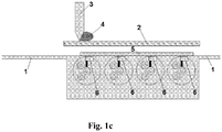
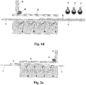
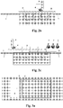
- FIG. 1a to 1d each schematically depict a device according to an embodiment the preferred second principal embodiment of the present invention for producing indicia by magnetic orienting of magnetic or magnetizable particles in an ink or coating composition on a sheet of substrate material, and illustrate an embodiment of the printing process:
- the sheet (5) is in printing position; the printing screen (2), the squeegee (3), and the ink (4) are in removed position.
- the magnet assemblies (6) are in applied position, orienting the magnetic or magnetizable particles in the printed ink.
- the printed and oriented sheet (5) is unloaded from the printing platen (1) of the flat-bed screen-printing machine.
- the magnet assemblies (6) are concomitantly moving into removed position.
- the printed ink is cured through the action of UV-drying equipment (7), fixing the magnetic or magnetizable particles in the oriented state.
- the sheet (5) is in printing position, the printing screen (2) is in lowered position, and the squeegee (3) moves the ink (4) over the screen (2), printing the sheet (5).
- the magnet assemblies (6) are in applied position, orienting the magnetic or magnetizable particles in the printed ink concomitantly with the printing process.
- the sheet (5) is in printing position, the printing screen (2) is in lowered position, and the squeegee (3) moves the ink (4) over the screen (2), printing the sheet (5).
- the magnet assemblies in applied position orient the magnetic or magnetizable particles in the printed ink concomitantly with the printing process.
- the flat printing screen may be of any type known in the art of screen-printing; it comprises a frame, made e.g. of wood, or preferably of aluminum, and a screen-printing mesh carried by the said frame.
- the screen-printing mesh, carrier of the printing stencil may in particular be a piece of porous, finely woven fabric, multi-filament ( Fig. 5a, 5b) or mono-filament ( Fig. 5c ), made of nylon, polyester or stainless steel. Most preferred is a mono-filament frame of low-elongation polyester, or a stainless steel frame.
- the screen-printing mesh may be a chemically etched, a laser-etched, or a galvanically formed porous metal foil ( Fig. 5e ), e.g. a stainless steel foil.
- Screen and metallic parts in contact with the printing ink and/or the printed substrate should be of non-magnetic material, in order to avoid any interference with the magnetic pigments and the magnetic orientation process.
- the screen-printing mesh is further characterized by its weaving parameters, i.e. the weaving scheme, the mesh count (mesh/inch or mesh/cm), the mesh thickness (in micrometers), and the thread diameter (in micrometers). From these, the aperture of the holes (in micrometers) and the theoretical ink deposit (in micrometers) can be derived.
- the mesh thickness is generally somewhat lower than twice the thread diameter, due to the staggered undulation of the thread, allowing for some vertical compression (calandering; Fig. 5d ).
- the screen-printing mesh is an important element of the present invention, which must be chosen such as to have the appropriate mesh size and thickness for printing the ink or coating composition comprising the most preferred optically variable magnetic or magnetizable pigment particles.
- the film thickness of the printed ink deposit in order to allow for an easy orientation of the particles, should preferably be about the average pigment particle size, i.e. in the range of 15 to 20 micrometers.
- the screen-printing mesh should have a free mesh aperture of about twice the top-cut of the pigment particle size, in our case thus an aperture in the range of 50 to 70 micrometers.
- the screen-printing mesh used in the present invention has therefore a preferred mesh aperture comprised in the range of 40 to 90 micrometers, most preferred is a mesh aperture in the range of 50 to 70 micrometers.
- the mesh has further a preferred mesh count comprised in the range of 150 to 300 mesh/inch (corresponding to 60 to 120 mesh/cm), most preferred is a mesh count in the range of 180 to 250 mesh/inch (corresponding to 72 to 100 mesh/cm).
- the mesh has a preferred thread diameter comprised in the range of 30 to 70 micrometers, most preferred is a thread diameter in the range of 45 to 55 micrometers.
- FIG. 6 depicts a cross section through a mono-filament screen-printing mesh carrying a photoresist printing stencil and to Figures 5f and 5g which show a computer-to-screen printing stencil, respectively a photoresist printing stencil.
- the printing stencil is the carrier of the printing information. It is advantageouslyproduced through photoresist technology, wherein the whole of the screen-printing mesh is in a first step coated with a photoresist, said photoresist is in a second step photographically exposed to the printing information (positive or negative, depending on the resist type), and the exposed resist is in a third step chemically developed such as to selectively remove it from the screen-printing mesh in the zones where ink is to be printed.
- the stencil can also be produced through an unselective coating of the whole mesh, followed by a selective mechanical ablation of the coating where ink is to be printed, or even more advantageously through selective Ink-Jet printing directly onto the mesh (Computer-to-Screen technology; Fig. 5f ).
- the devices and the processes according to the present invention can be used for producing indicia through the magnetic orienting of magnetic or magnetizable particles in a coating composition on a sheet or document.
- Said document may in particular be a security document, preferably chosen from the group consisting of the banknotes, the value documents, the cards, the transportation tickets, the passports, the identity documents, the access documents, the tax-excise documents and the product labels.
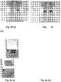
- the silkscreen printing unit (Fig. 4a (i) ) is a laboratory flat-screen, flat-bed proofing press and consists of a printing station and a vacuum pump to retain the printing substrate on the printing platen.
- the printing platen was adapted to contain two magnetic orienting units ( Fig. 4a (ii) : units inserted; (iii) units removed).
- the flat printing screen is based on a woven mesh of single-stranded polyester (S) or of polyester thread (T).
- Such screen mesh can, e.g., be obtained from Shangshai Polyester Screen Printing Mesh Co., Ltd., Shanghai, China.
- the following mesh qualities were successfully used: mesh type mesh/inch aperture ( ⁇ m) thread ( ⁇ m) ink deposit ( ⁇ m) 61-64PW(T) 155 90 64 30 77-48PW(S) 195 77 48 28 77-55PW(T) 195 67 55 24 90-48PW(T) 230 56 48 19 120-31PW(S) 305 49 31 17
- the printing stencil is produced on the mesh by photoresist technology, as known in the art.
- the so obtained screen-printing mesh is mounted on an aluminum frame fitting onto the flat-bed proofing press.
- the printing unit comprises a printing-screen ( Fig. 4a (i) ), a printing platen ( Fig. 4b(i,ii) ), magnet assemblies (Fig. 4c(i,ii) ) and supporting blocks ( Fig. 4d ). Magnet assemblies and supporting blocks, as well as the mechanical parts for moving the magnet assemblies, form together a magnetic orienting unit.
- the printing platen ( Fig. 4b(i,ii) ) was made so as to have 2 parallel channels, to hold and position two magnet assemblies.
- the "Light Switch" type of magnet assembly can be easily adapted for producing other customized effects
- the process for producing indicia through the magnetic orienting of magnetic or magnetizable particles in an ink or coating composition on a sheet of substrate material comprises the sequential steps of:
Landscapes
- Engineering & Computer Science (AREA)
- Mechanical Engineering (AREA)
- Business, Economics & Management (AREA)
- Accounting & Taxation (AREA)
- Finance (AREA)
- General Physics & Mathematics (AREA)
- Physics & Mathematics (AREA)
- Theoretical Computer Science (AREA)
- Printing Methods (AREA)
- Application Of Or Painting With Fluid Materials (AREA)
- Screen Printers (AREA)
- Credit Cards Or The Like (AREA)
- Coating Apparatus (AREA)
Claims (19)
- Dispositif comprenant :une unité de sérigraphie à lit plat ayant un cadre d'impression plat (2) et une platine d'impression (1) destinée à recevoir une feuille de matériau substrat (5), la platine d'impression (1) ayant une surface supérieure faisant face au cadre d'impression (2) et une première direction le long de sa surface supérieure le long de laquelle ladite feuille (5) est déchargeable ; etune unité d'orientation magnétique comprenant de multiples ensembles aimants (6) ;dans lequel ladite unité d'orientation magnétique est disposée au-dessous de la surface supérieure de la platine d'impression (1), caractérisé en ce quelesdits multiples ensembles aimants (6) sont disposés le long de ladite première direction, et tous lesdits ensembles aimants (6) sont mobiles simultanément d'une première position éloignée de la surface supérieure de la platine d'impression (1) à une deuxième position proche de la surface supérieure de la platine d'impression (1).
- Dispositif selon la revendication 1, dans lequel lesdits ensembles aimants (6) sont mobiles entre la première position et la deuxième position dans un mouvement de va-et-vient le long d'une deuxième direction transversale à la surface supérieure de la platine d'impression (1).
- Dispositif selon la revendication 1, dans lequel lesdits ensembles aimants (6) sont mobiles entre la première position et la deuxième position dans un mouvement de roulement d'avant en arrière.
- Dispositif selon la revendication 3, le dispositif étant configuré pour déplacer les ensembles aimants (6) en synchronisation avec le déchargement de la feuille (5), de telle sorte qu'un flou d'une image magnétique produite sur la feuille (5) est empêché.
- Dispositif selon l'une quelconque des revendications précédentes, dans lequel au moins un des ensembles aimants (6) comprend une plaque gravée et aimantée de matériau magnétique permanent.
- Dispositif selon la revendication 5, dans lequel ladite plaque gravée et aimantée est un matériau composite, comprenant un polymère comme liant structural, de préférence un polymère de type caoutchouc ou plastique, et une poudre magnétique permanente comme charge.
- Dispositif selon l'une quelconque des revendications 5 à 6, dans lequel au moins un desdits ensembles aimants (6) comprend au moins un aimant permanent supplémentaire, monté dans une position qui le maintient contre les forces magnétiques intrinsèques agissant entre l'au moins un desdits ensembles aimants (6) et la plaque gravée aimantée.
- Dispositif selon l'une quelconque des revendications précédentes, dans lequel le cadre d'impression (2) a une ouverture de maille dans la gamme de 40 à 90 micromètres, de préférence dans la gamme de 50 à 70 micromètres.
- Procédé de production d'indices comprenant les étapes consistant à :a) se procurer un dispositif selon l'une quelconque des revendications 1 à 8 ;b) charger sur la platine d'impression (1) du dispositif une feuille de matériau substrat (5) portant au moins sur une partie de sa surface une encre ou composition de revêtement humide (4) comprenant des particules magnétiques ou aimantables ;c) déplacer simultanément tous les ensembles aimants (6) du dispositif d'une première position éloignée de la surface supérieure de la platine d'impression (1) à une deuxième position proche de la surface supérieure de la platine d'impression (1), pour orienter ainsi lesdites particules de pigment magnétiques ou aimantables dans l'encre ou composition de revêtement humide (4) ;d) faire retourner les ensembles aimants (6) à ladite première position ;e) décharger la feuille (5) de la platine d'impression (1) ; etf) durcir l'encre (4).
- Procédé selon la revendication 9, dans lequel ledit déplacement des ensembles aimants (6) entre la première position et la deuxième position est effectué dans un mouvement de va-et-vient le long d'une deuxième direction transversale à la surface supérieure de la platine d'impression (1).
- Procédé selon la revendication 9, dans lequel ledit déplacement des ensembles aimants (6) entre la première position et la deuxième position est effectué dans un mouvement de roulement d'avant en arrière.
- Procédé selon la revendication 11, dans lequel ledit déplacement des ensembles aimants (6) et ledit déchargement de la feuille (5) sont effectués dans un mouvement synchronisé de manière à empêcher un flou de l'image magnétique produite sur la feuille (5).
- Procédé selon l'une quelconque des revendications 9 à 12, dans lequel l'étape de chargement d'une feuille de matériau substrat (5) sur la platine d'impression (1) du dispositif comporte une étape de revêtement ou d'impression de la surface de la feuille (5) au moins en partie avec une composition de revêtement ou encre humide (4) comprenant des particules magnétiques ou aimantables.
- Procédé selon la revendication 13, dans lequel le revêtement ou l'impression est effectué en utilisant un cadre d'impression plat (2) ayant une ouverture de maille dans la gamme de 40 à 90 micromètres, de préférence dans la gamme de 50 à 70 micromètres.
- Procédé selon une des revendications 13 à 14, dans lequel le revêtement ou l'impression est effectué en utilisant une composition (4) comprenant des particules de pigment magnétiques optiquement variables.
- Procédé selon une des revendications 13 à 15, dans lequel ladite étape de revêtement ou d'impression est effectuée simultanément à ladite orientation magnétique des particules de pigment.
- Procédé selon une des revendications 13 à 16, dans lequel lesdits ensembles aimants (6) sont déplacés vers la platine d'impression (1) avant l'impression de ladite feuille (5).
- Utilisation d'un dispositif selon l'une quelconque des revendications 1 à 8 pour la production d'indices comprenant des particules magnétiques ou aimantables orientées magnétiquement dans une encre ou composition de revêtement (4) sur une feuille de matériau substrat (5).
- Utilisation selon la revendication 18, dans laquelle ladite feuille (5) est choisie dans le groupe constitué par les billets de banque, les documents de valeur, les cartes, les tickets de transport, les passeports, les documents d'identité, les documents d'accès, les documents de taxes-droits d'accise, et les étiquettes de produits.
Applications Claiming Priority (2)
| Application Number | Priority Date | Filing Date | Title |
|---|---|---|---|
| IB2008003406 | 2008-12-10 | ||
| PCT/EP2009/066826 WO2010066838A1 (fr) | 2008-12-10 | 2009-12-10 | Sérigraphie et orientation magnétique |
Publications (2)
| Publication Number | Publication Date |
|---|---|
| EP2279081A1 EP2279081A1 (fr) | 2011-02-02 |
| EP2279081B1 true EP2279081B1 (fr) | 2018-04-04 |
Family
ID=40373513
Family Applications (1)
| Application Number | Title | Priority Date | Filing Date |
|---|---|---|---|
| EP09805921.5A Active EP2279081B1 (fr) | 2008-12-10 | 2009-12-10 | Impression par sérigraphie et orientation magnétique |
Country Status (18)
| Country | Link |
|---|---|
| US (1) | US8794140B2 (fr) |
| EP (1) | EP2279081B1 (fr) |
| JP (1) | JP5544592B2 (fr) |
| KR (1) | KR20110104494A (fr) |
| AP (1) | AP2011005752A0 (fr) |
| AR (1) | AR074560A1 (fr) |
| AU (1) | AU2009324356B2 (fr) |
| BR (1) | BRPI0923243A2 (fr) |
| CA (1) | CA2744922C (fr) |
| CL (1) | CL2011001376A1 (fr) |
| CU (1) | CU20110131A7 (fr) |
| EA (1) | EA019671B1 (fr) |
| MA (1) | MA32890B1 (fr) |
| MX (1) | MX2011005760A (fr) |
| TW (1) | TWI487626B (fr) |
| UA (1) | UA107071C2 (fr) |
| WO (1) | WO2010066838A1 (fr) |
| ZA (1) | ZA201104252B (fr) |
Families Citing this family (23)
| Publication number | Priority date | Publication date | Assignee | Title |
|---|---|---|---|---|
| JP5406112B2 (ja) * | 2010-04-27 | 2014-02-05 | インターメタリックス株式会社 | 粒界拡散処理用塗布装置 |
| TWI587104B (zh) | 2010-09-24 | 2017-06-11 | 西克帕控股有限公司 | 用於產生磁感應視覺效果之裝置、系統和方法 |
| CN102218893B (zh) * | 2011-05-11 | 2012-07-04 | 武汉纺织大学 | 丝网印花台板间歇运动的无接触式驱动装置 |
| ITVI20110122A1 (it) * | 2011-05-13 | 2012-11-14 | St Microelectronics Srl | Metodo e apparato per la fabbricazione di lead frames |
| CN103009786A (zh) * | 2011-09-23 | 2013-04-03 | 潘美珍 | 立体纹饰丝网印刷装置及方法 |
| CN103171252B (zh) * | 2013-03-29 | 2014-12-03 | 中钞油墨有限公司 | 平板丝网印刷机上的磁定位装置 |
| DE202013004745U1 (de) * | 2013-05-23 | 2014-08-26 | Exentis-Knowledge Ag | Anlage zur Herstellung von dreidimensionalen Siebdrucken |
| BR112015031227B1 (pt) * | 2013-06-14 | 2022-03-08 | Sicpa Holding Sa | Dispositivo gerador de campo magnético e seu uso, conjunto de impressão e processo para produzir uma camada de efeito óptico |
| DE102013015277B4 (de) | 2013-09-16 | 2016-02-11 | Schwarz Druck GmbH | Orientierung magnetisch orientierbarer Partikel in einer Farbe mit mehreren einander überlagerten Magnetfeldern |
| RU2017105124A (ru) | 2014-07-30 | 2018-08-28 | Сикпа Холдинг Са | Способы получения слоев с оптическим эффектом с применением ременного привода |
| CN107073926A (zh) * | 2014-08-01 | 2017-08-18 | 康宁股份有限公司 | 丝网印刷设备和方法 |
| AU2015306179A1 (en) * | 2014-08-22 | 2016-12-22 | Sicpa Holding Sa | Apparatus and method for producing optical effect layers |
| US20180264801A1 (en) * | 2015-01-16 | 2018-09-20 | Microsoft Technology Licensing, Llc | Formation of substrates having ink including magnetic material |
| AR107681A1 (es) * | 2016-02-29 | 2018-05-23 | Sicpa Holding Sa | Aparatos y procesos para producir capas con efecto óptico que comprenden partículas de pigmento no esféricas orientadas magnéticas, o magnetizables |
| US10357991B2 (en) | 2016-12-19 | 2019-07-23 | Viavi Solutions Inc. | Security ink based security feature |
| EP3576888B1 (fr) | 2017-01-31 | 2021-03-31 | Sicpa Holding Sa | Appareils et procédés de production de couches à effet optique |
| WO2019201481A1 (fr) * | 2018-04-18 | 2019-10-24 | Koenig & Bauer Ag | Dispositifs, machines et procédé d'application et d'orientation de particules magnétiques ou magnétisables sur un substrat en forme de bande ou de feuille |
| CN109334225B (zh) * | 2018-09-21 | 2020-09-01 | 惠州市嘉信达科技有限公司 | 一种磁性颜料的印刷设备及印刷方法 |
| RU2719317C1 (ru) * | 2019-11-26 | 2020-04-17 | Общество с ограниченной ответственностью "Инновационная компания "ЯЛОС" | Способ нанесения термоплавких составов |
| JP7477366B2 (ja) * | 2020-05-25 | 2024-05-01 | パナソニックホールディングス株式会社 | 磁性粉体の印刷装置および磁性粉体の印刷方法 |
| KR20250129120A (ko) | 2020-09-09 | 2025-08-28 | 자빌 인코퍼레이티드 | 디자인이 향상된 3d 인쇄되는 지지 블록 |
| DE102021110864B4 (de) * | 2021-04-28 | 2023-03-02 | Koenig & Bauer Ag | Vorrichtung zum Ausrichten von magnetischen oder magnetisierbaren Partikeln sowie Maschine zur Erzeugung optisch variabler Bildelemente |
| CN117341377A (zh) * | 2022-06-28 | 2024-01-05 | 中钞特种防伪科技有限公司 | 防伪元件和制造防伪元件的方法 |
Family Cites Families (19)
| Publication number | Priority date | Publication date | Assignee | Title |
|---|---|---|---|---|
| DE3732116A1 (de) * | 1986-10-01 | 1988-04-21 | Trinitas Ag | Magnetisierbare siebdruckfarbe und verfahren zur herstellung eines flaechenmagneten |
| US4838648A (en) | 1988-05-03 | 1989-06-13 | Optical Coating Laboratory, Inc. | Thin film structure having magnetic and color shifting properties |
| EP1239307A1 (fr) | 2001-03-09 | 2002-09-11 | Sicpa Holding S.A. | Système magnétique d'interférence de couches minces |
| US7258900B2 (en) * | 2002-07-15 | 2007-08-21 | Jds Uniphase Corporation | Magnetic planarization of pigment flakes |
| EP1403333A1 (fr) | 2002-09-24 | 2004-03-31 | Sicpa Holding S.A. | Procédé et système d' encres pour marquer et authentifier les articles |
| ES2596079T3 (es) | 2003-06-30 | 2017-01-04 | Kba-Notasys Sa | Máquina de impresión y método |
| EP1493590A1 (fr) | 2003-07-03 | 2005-01-05 | Sicpa Holding S.A. | Procédé et moyens de production d'un dessin induit par magnétisme dans une composition de revêtement contenant des particules magnétiques |
| EP1529653A1 (fr) | 2003-11-07 | 2005-05-11 | Sicpa Holding S.A. | Document de sécurité, méthode de production d'un document de sécurité et l'utilisation d'un document de sécurité |
| EP1669213A1 (fr) | 2004-12-09 | 2006-06-14 | Sicpa Holding S.A. | Elément de sécurité avec un aspect dépendent de l'angle d'observation |
| EP1854852A1 (fr) | 2006-05-12 | 2007-11-14 | Sicpa Holding S.A. | Composition de revêtement pour la fabrication d'images induites magnétiquement |
| EP1880866A1 (fr) | 2006-07-19 | 2008-01-23 | Sicpa Holding S.A. | Couche d'image orientée sur support transparent |
| BRPI0717147A2 (pt) | 2006-10-17 | 2013-10-15 | Sicpa Holding Sa | Métodos e meios para produzir uma imagem magneticamente induzida em um revestimento contendo partículas magnéticas |
| EP1961559A1 (fr) * | 2007-02-20 | 2008-08-27 | Kba-Giori S.A. | Corps cylindrique d'orientation de paillettes magnétiques contenues dans une encre ou un vernis appliquées sur un substrat en forme de feuille ou de bande |
| US20080217575A1 (en) | 2007-03-06 | 2008-09-11 | Bruce Kenneth Bachman | Coating formulation for magnetic imaging in a wet film |
| EP2014729A1 (fr) | 2007-07-09 | 2009-01-14 | Sicpa Holding S.A. | Encre d'impression d' intaglio avec un agent de séchage contenant Vanadium |
| MX2010000814A (es) | 2007-07-20 | 2010-03-01 | Sicpa Holding Sa | Tintas para impresion intaglio. |
| KR101655398B1 (ko) | 2008-10-03 | 2016-09-07 | 시크파 홀딩 에스에이 | 특정의 반사 파장을 갖는 쌍으로 된 광학적 가변 보안 부재 |
| TWI443612B (zh) | 2009-04-07 | 2014-07-01 | Sicpa Holding Sa | 受壓變色保密元件 |
| TWI478990B (zh) | 2009-04-09 | 2015-04-01 | Sicpa Holding Sa | 明亮之磁性凹刻印刷油墨 |
-
2009
- 2009-12-08 TW TW098141866A patent/TWI487626B/zh not_active IP Right Cessation
- 2009-12-09 AR ARP090104762A patent/AR074560A1/es active IP Right Grant
- 2009-12-10 US US13/133,850 patent/US8794140B2/en active Active
- 2009-12-10 AP AP2011005752A patent/AP2011005752A0/xx unknown
- 2009-12-10 CA CA2744922A patent/CA2744922C/fr not_active Expired - Fee Related
- 2009-12-10 UA UAA201108566A patent/UA107071C2/ru unknown
- 2009-12-10 AU AU2009324356A patent/AU2009324356B2/en not_active Ceased
- 2009-12-10 EP EP09805921.5A patent/EP2279081B1/fr active Active
- 2009-12-10 MX MX2011005760A patent/MX2011005760A/es active IP Right Grant
- 2009-12-10 BR BRPI0923243A patent/BRPI0923243A2/pt not_active Application Discontinuation
- 2009-12-10 KR KR1020117013682A patent/KR20110104494A/ko not_active Withdrawn
- 2009-12-10 EA EA201190057A patent/EA019671B1/ru not_active IP Right Cessation
- 2009-12-10 JP JP2011540104A patent/JP5544592B2/ja not_active Expired - Fee Related
- 2009-12-10 WO PCT/EP2009/066826 patent/WO2010066838A1/fr not_active Ceased
-
2011
- 2011-06-08 CL CL2011001376A patent/CL2011001376A1/es unknown
- 2011-06-08 ZA ZA2011/04252A patent/ZA201104252B/en unknown
- 2011-06-09 CU CU20110131A patent/CU20110131A7/es unknown
- 2011-06-10 MA MA33930A patent/MA32890B1/fr unknown
Also Published As
| Publication number | Publication date |
|---|---|
| CL2011001376A1 (es) | 2011-10-28 |
| EA201190057A1 (ru) | 2012-03-30 |
| WO2010066838A1 (fr) | 2010-06-17 |
| JP5544592B2 (ja) | 2014-07-09 |
| US8794140B2 (en) | 2014-08-05 |
| EA019671B1 (ru) | 2014-05-30 |
| KR20110104494A (ko) | 2011-09-22 |
| AU2009324356B2 (en) | 2014-09-25 |
| CU20110131A7 (es) | 2012-06-21 |
| BRPI0923243A2 (pt) | 2017-06-06 |
| AR074560A1 (es) | 2011-01-26 |
| AP2011005752A0 (en) | 2011-06-30 |
| TW201028296A (en) | 2010-08-01 |
| MA32890B1 (fr) | 2011-12-01 |
| TWI487626B (zh) | 2015-06-11 |
| ZA201104252B (en) | 2012-02-29 |
| CA2744922A1 (fr) | 2010-06-17 |
| EP2279081A1 (fr) | 2011-02-02 |
| MX2011005760A (es) | 2011-11-18 |
| US20120055355A1 (en) | 2012-03-08 |
| AU2009324356A1 (en) | 2010-06-17 |
| UA107071C2 (en) | 2014-11-25 |
| JP2012511448A (ja) | 2012-05-24 |
| CA2744922C (fr) | 2016-11-29 |
Similar Documents
| Publication | Publication Date | Title |
|---|---|---|
| EP2279081B1 (fr) | Impression par sérigraphie et orientation magnétique | |
| JP2012511448A5 (fr) | ||
| US8893614B2 (en) | Device and method for magnetically transferring indicia to a coating composition applied to a substrate | |
| EP2433798B1 (fr) | Système et procédé d'orientation de paillettes magnétiques contenues dans une encre ou un véhicule vernis appliquées sur un substrat en forme de feuille ou de bande | |
| CN109311051B (zh) | 用于生产效应层的方法 | |
| DK2542417T3 (en) | SAFETY THREAD OR STRIP THAT INCLUDES ORIENTED MAGNETIC PARTICLES IN PRINT HEARING AND PROCEDURE FOR MANUFACTURING THIS | |
| JP7434688B2 (ja) | 光学効果層を生成するためのプロセス | |
| CN112512829A (zh) | 用于生产包含取向的磁性或可磁化颜料颗粒的光学效应层的组件和方法 | |
| EP1937415A1 (fr) | Procédé et dispositif permettant de créer des marques induites magnétiquement dans un revêtement contenant des particules magnétiques | |
| CN104023982B (zh) | 使用柔性版印刷辊构造的柔性版印刷 | |
| CN102267277A (zh) | 磁性定向和印刷 | |
| CN212353228U (zh) | 印刷设备 | |
| HK40085752B (zh) | 用於生成光学可变图元的机器 | |
| OA19932A (en) | Assemblies and processes for producing optical effect layers comprising oriented magnetic or magnetizable pigment particles. | |
| HK40039884B (en) | Assemblies and processes for producing optical effect layers comprising oriented magnetic or magnetizable pigment particles | |
| HK40039884A (en) | Assemblies and processes for producing optical effect layers comprising oriented magnetic or magnetizable pigment particles | |
| OA19931A (en) | Processes for producing optical effects layers. | |
| JPH0948106A (ja) | 印刷物の製造方法 |
Legal Events
| Date | Code | Title | Description |
|---|---|---|---|
| PUAI | Public reference made under article 153(3) epc to a published international application that has entered the european phase |
Free format text: ORIGINAL CODE: 0009012 |
|
| 17P | Request for examination filed |
Effective date: 20101026 |
|
| AK | Designated contracting states |
Kind code of ref document: A1 Designated state(s): AT BE BG CH CY CZ DE DK EE ES FI FR GB GR HR HU IE IS IT LI LT LU LV MC MK MT NL NO PL PT RO SE SI SK SM TR |
|
| AX | Request for extension of the european patent |
Extension state: AL BA RS |
|
| RAP1 | Party data changed (applicant data changed or rights of an application transferred) |
Owner name: SICPA HOLDING SA Owner name: CHINA BANKNOTE SICPA SECURITY INK CO. LTD. |
|
| REG | Reference to a national code |
Ref country code: HK Ref legal event code: DE Ref document number: 1153435 Country of ref document: HK |
|
| 17Q | First examination report despatched |
Effective date: 20120529 |
|
| REG | Reference to a national code |
Ref country code: DE Ref legal event code: R079 Ref document number: 602009051643 Country of ref document: DE Free format text: PREVIOUS MAIN CLASS: B41F0015080000 Ipc: B41F0015360000 |
|
| GRAP | Despatch of communication of intention to grant a patent |
Free format text: ORIGINAL CODE: EPIDOSNIGR1 |
|
| STAA | Information on the status of an ep patent application or granted ep patent |
Free format text: STATUS: GRANT OF PATENT IS INTENDED |
|
| RIC1 | Information provided on ipc code assigned before grant |
Ipc: B41F 15/12 20060101ALI20171115BHEP Ipc: B41F 15/22 20060101ALI20171115BHEP Ipc: B41M 1/12 20060101ALI20171115BHEP Ipc: H05K 3/12 20060101ALI20171115BHEP Ipc: B41F 15/36 20060101AFI20171115BHEP Ipc: H05K 1/02 20060101ALI20171115BHEP Ipc: B41F 15/08 20060101ALI20171115BHEP |
|
| INTG | Intention to grant announced |
Effective date: 20171130 |
|
| GRAS | Grant fee paid |
Free format text: ORIGINAL CODE: EPIDOSNIGR3 |
|
| GRAA | (expected) grant |
Free format text: ORIGINAL CODE: 0009210 |
|
| STAA | Information on the status of an ep patent application or granted ep patent |
Free format text: STATUS: THE PATENT HAS BEEN GRANTED |
|
| AK | Designated contracting states |
Kind code of ref document: B1 Designated state(s): AT BE BG CH CY CZ DE DK EE ES FI FR GB GR HR HU IE IS IT LI LT LU LV MC MK MT NL NO PL PT RO SE SI SK SM TR |
|
| AX | Request for extension of the european patent |
Extension state: AL BA RS |
|
| REG | Reference to a national code |
Ref country code: GB Ref legal event code: FG4D |
|
| REG | Reference to a national code |
Ref country code: CH Ref legal event code: EP |
|
| REG | Reference to a national code |
Ref country code: AT Ref legal event code: REF Ref document number: 985169 Country of ref document: AT Kind code of ref document: T Effective date: 20180415 |
|
| REG | Reference to a national code |
Ref country code: IE Ref legal event code: FG4D |
|
| REG | Reference to a national code |
Ref country code: DE Ref legal event code: R096 Ref document number: 602009051643 Country of ref document: DE |
|
| REG | Reference to a national code |
Ref country code: HK Ref legal event code: WD Ref document number: 1153435 Country of ref document: HK |
|
| REG | Reference to a national code |
Ref country code: NL Ref legal event code: MP Effective date: 20180404 |
|
| REG | Reference to a national code |
Ref country code: LT Ref legal event code: MG4D |
|
| PG25 | Lapsed in a contracting state [announced via postgrant information from national office to epo] |
Ref country code: NL Free format text: LAPSE BECAUSE OF FAILURE TO SUBMIT A TRANSLATION OF THE DESCRIPTION OR TO PAY THE FEE WITHIN THE PRESCRIBED TIME-LIMIT Effective date: 20180404 |
|
| PG25 | Lapsed in a contracting state [announced via postgrant information from national office to epo] |
Ref country code: SE Free format text: LAPSE BECAUSE OF FAILURE TO SUBMIT A TRANSLATION OF THE DESCRIPTION OR TO PAY THE FEE WITHIN THE PRESCRIBED TIME-LIMIT Effective date: 20180404 Ref country code: PL Free format text: LAPSE BECAUSE OF FAILURE TO SUBMIT A TRANSLATION OF THE DESCRIPTION OR TO PAY THE FEE WITHIN THE PRESCRIBED TIME-LIMIT Effective date: 20180404 Ref country code: ES Free format text: LAPSE BECAUSE OF FAILURE TO SUBMIT A TRANSLATION OF THE DESCRIPTION OR TO PAY THE FEE WITHIN THE PRESCRIBED TIME-LIMIT Effective date: 20180404 Ref country code: LT Free format text: LAPSE BECAUSE OF FAILURE TO SUBMIT A TRANSLATION OF THE DESCRIPTION OR TO PAY THE FEE WITHIN THE PRESCRIBED TIME-LIMIT Effective date: 20180404 Ref country code: NO Free format text: LAPSE BECAUSE OF FAILURE TO SUBMIT A TRANSLATION OF THE DESCRIPTION OR TO PAY THE FEE WITHIN THE PRESCRIBED TIME-LIMIT Effective date: 20180704 Ref country code: BG Free format text: LAPSE BECAUSE OF FAILURE TO SUBMIT A TRANSLATION OF THE DESCRIPTION OR TO PAY THE FEE WITHIN THE PRESCRIBED TIME-LIMIT Effective date: 20180704 Ref country code: FI Free format text: LAPSE BECAUSE OF FAILURE TO SUBMIT A TRANSLATION OF THE DESCRIPTION OR TO PAY THE FEE WITHIN THE PRESCRIBED TIME-LIMIT Effective date: 20180404 |
|
| PG25 | Lapsed in a contracting state [announced via postgrant information from national office to epo] |
Ref country code: HR Free format text: LAPSE BECAUSE OF FAILURE TO SUBMIT A TRANSLATION OF THE DESCRIPTION OR TO PAY THE FEE WITHIN THE PRESCRIBED TIME-LIMIT Effective date: 20180404 Ref country code: LV Free format text: LAPSE BECAUSE OF FAILURE TO SUBMIT A TRANSLATION OF THE DESCRIPTION OR TO PAY THE FEE WITHIN THE PRESCRIBED TIME-LIMIT Effective date: 20180404 Ref country code: GR Free format text: LAPSE BECAUSE OF FAILURE TO SUBMIT A TRANSLATION OF THE DESCRIPTION OR TO PAY THE FEE WITHIN THE PRESCRIBED TIME-LIMIT Effective date: 20180705 |
|
| REG | Reference to a national code |
Ref country code: AT Ref legal event code: MK05 Ref document number: 985169 Country of ref document: AT Kind code of ref document: T Effective date: 20180404 |
|
| PG25 | Lapsed in a contracting state [announced via postgrant information from national office to epo] |
Ref country code: PT Free format text: LAPSE BECAUSE OF FAILURE TO SUBMIT A TRANSLATION OF THE DESCRIPTION OR TO PAY THE FEE WITHIN THE PRESCRIBED TIME-LIMIT Effective date: 20180806 |
|
| REG | Reference to a national code |
Ref country code: DE Ref legal event code: R097 Ref document number: 602009051643 Country of ref document: DE |
|
| PG25 | Lapsed in a contracting state [announced via postgrant information from national office to epo] |
Ref country code: DK Free format text: LAPSE BECAUSE OF FAILURE TO SUBMIT A TRANSLATION OF THE DESCRIPTION OR TO PAY THE FEE WITHIN THE PRESCRIBED TIME-LIMIT Effective date: 20180404 Ref country code: SK Free format text: LAPSE BECAUSE OF FAILURE TO SUBMIT A TRANSLATION OF THE DESCRIPTION OR TO PAY THE FEE WITHIN THE PRESCRIBED TIME-LIMIT Effective date: 20180404 Ref country code: CZ Free format text: LAPSE BECAUSE OF FAILURE TO SUBMIT A TRANSLATION OF THE DESCRIPTION OR TO PAY THE FEE WITHIN THE PRESCRIBED TIME-LIMIT Effective date: 20180404 Ref country code: EE Free format text: LAPSE BECAUSE OF FAILURE TO SUBMIT A TRANSLATION OF THE DESCRIPTION OR TO PAY THE FEE WITHIN THE PRESCRIBED TIME-LIMIT Effective date: 20180404 Ref country code: AT Free format text: LAPSE BECAUSE OF FAILURE TO SUBMIT A TRANSLATION OF THE DESCRIPTION OR TO PAY THE FEE WITHIN THE PRESCRIBED TIME-LIMIT Effective date: 20180404 Ref country code: RO Free format text: LAPSE BECAUSE OF FAILURE TO SUBMIT A TRANSLATION OF THE DESCRIPTION OR TO PAY THE FEE WITHIN THE PRESCRIBED TIME-LIMIT Effective date: 20180404 |
|
| PLBE | No opposition filed within time limit |
Free format text: ORIGINAL CODE: 0009261 |
|
| STAA | Information on the status of an ep patent application or granted ep patent |
Free format text: STATUS: NO OPPOSITION FILED WITHIN TIME LIMIT |
|
| PG25 | Lapsed in a contracting state [announced via postgrant information from national office to epo] |
Ref country code: SM Free format text: LAPSE BECAUSE OF FAILURE TO SUBMIT A TRANSLATION OF THE DESCRIPTION OR TO PAY THE FEE WITHIN THE PRESCRIBED TIME-LIMIT Effective date: 20180404 Ref country code: IT Free format text: LAPSE BECAUSE OF FAILURE TO SUBMIT A TRANSLATION OF THE DESCRIPTION OR TO PAY THE FEE WITHIN THE PRESCRIBED TIME-LIMIT Effective date: 20180404 |
|
| 26N | No opposition filed |
Effective date: 20190107 |
|
| PG25 | Lapsed in a contracting state [announced via postgrant information from national office to epo] |
Ref country code: SI Free format text: LAPSE BECAUSE OF FAILURE TO SUBMIT A TRANSLATION OF THE DESCRIPTION OR TO PAY THE FEE WITHIN THE PRESCRIBED TIME-LIMIT Effective date: 20180404 |
|
| PG25 | Lapsed in a contracting state [announced via postgrant information from national office to epo] |
Ref country code: MC Free format text: LAPSE BECAUSE OF FAILURE TO SUBMIT A TRANSLATION OF THE DESCRIPTION OR TO PAY THE FEE WITHIN THE PRESCRIBED TIME-LIMIT Effective date: 20180404 Ref country code: LU Free format text: LAPSE BECAUSE OF NON-PAYMENT OF DUE FEES Effective date: 20181210 |
|
| REG | Reference to a national code |
Ref country code: IE Ref legal event code: MM4A |
|
| REG | Reference to a national code |
Ref country code: BE Ref legal event code: MM Effective date: 20181231 |
|
| PG25 | Lapsed in a contracting state [announced via postgrant information from national office to epo] |
Ref country code: IE Free format text: LAPSE BECAUSE OF NON-PAYMENT OF DUE FEES Effective date: 20181210 |
|
| PG25 | Lapsed in a contracting state [announced via postgrant information from national office to epo] |
Ref country code: BE Free format text: LAPSE BECAUSE OF NON-PAYMENT OF DUE FEES Effective date: 20181231 |
|
| PG25 | Lapsed in a contracting state [announced via postgrant information from national office to epo] |
Ref country code: MT Free format text: LAPSE BECAUSE OF NON-PAYMENT OF DUE FEES Effective date: 20181210 |
|
| PG25 | Lapsed in a contracting state [announced via postgrant information from national office to epo] |
Ref country code: TR Free format text: LAPSE BECAUSE OF FAILURE TO SUBMIT A TRANSLATION OF THE DESCRIPTION OR TO PAY THE FEE WITHIN THE PRESCRIBED TIME-LIMIT Effective date: 20180404 |
|
| PG25 | Lapsed in a contracting state [announced via postgrant information from national office to epo] |
Ref country code: CY Free format text: LAPSE BECAUSE OF FAILURE TO SUBMIT A TRANSLATION OF THE DESCRIPTION OR TO PAY THE FEE WITHIN THE PRESCRIBED TIME-LIMIT Effective date: 20180404 Ref country code: MK Free format text: LAPSE BECAUSE OF NON-PAYMENT OF DUE FEES Effective date: 20180404 Ref country code: HU Free format text: LAPSE BECAUSE OF FAILURE TO SUBMIT A TRANSLATION OF THE DESCRIPTION OR TO PAY THE FEE WITHIN THE PRESCRIBED TIME-LIMIT; INVALID AB INITIO Effective date: 20091210 |
|
| PG25 | Lapsed in a contracting state [announced via postgrant information from national office to epo] |
Ref country code: IS Free format text: LAPSE BECAUSE OF FAILURE TO SUBMIT A TRANSLATION OF THE DESCRIPTION OR TO PAY THE FEE WITHIN THE PRESCRIBED TIME-LIMIT Effective date: 20180804 |
|
| PGFP | Annual fee paid to national office [announced via postgrant information from national office to epo] |
Ref country code: CH Payment date: 20250101 Year of fee payment: 16 |
|
| REG | Reference to a national code |
Ref country code: CH Ref legal event code: U11 Free format text: ST27 STATUS EVENT CODE: U-0-0-U10-U11 (AS PROVIDED BY THE NATIONAL OFFICE) Effective date: 20260101 |
|
| PGFP | Annual fee paid to national office [announced via postgrant information from national office to epo] |
Ref country code: DE Payment date: 20251126 Year of fee payment: 17 |
|
| PGFP | Annual fee paid to national office [announced via postgrant information from national office to epo] |
Ref country code: GB Payment date: 20251119 Year of fee payment: 17 |
|
| PGFP | Annual fee paid to national office [announced via postgrant information from national office to epo] |
Ref country code: FR Payment date: 20251119 Year of fee payment: 17 |