EP2279344B1 - Anordnung zur erzeugung von elektrizität - Google Patents
Anordnung zur erzeugung von elektrizität Download PDFInfo
- Publication number
- EP2279344B1 EP2279344B1 EP09714497.6A EP09714497A EP2279344B1 EP 2279344 B1 EP2279344 B1 EP 2279344B1 EP 09714497 A EP09714497 A EP 09714497A EP 2279344 B1 EP2279344 B1 EP 2279344B1
- Authority
- EP
- European Patent Office
- Prior art keywords
- water conduit
- secondary water
- primary
- conduit
- primary water
- Prior art date
- Legal status (The legal status is an assumption and is not a legal conclusion. Google has not performed a legal analysis and makes no representation as to the accuracy of the status listed.)
- Not-in-force
Links
- 230000005611 electricity Effects 0.000 title claims description 43
- XLYOFNOQVPJJNP-UHFFFAOYSA-N water Substances O XLYOFNOQVPJJNP-UHFFFAOYSA-N 0.000 claims description 182
- 238000000034 method Methods 0.000 claims description 15
- 239000012530 fluid Substances 0.000 claims description 6
- 230000003466 anti-cipated effect Effects 0.000 description 1
Images


Classifications
-
- F—MECHANICAL ENGINEERING; LIGHTING; HEATING; WEAPONS; BLASTING
- F03—MACHINES OR ENGINES FOR LIQUIDS; WIND, SPRING, OR WEIGHT MOTORS; PRODUCING MECHANICAL POWER OR A REACTIVE PROPULSIVE THRUST, NOT OTHERWISE PROVIDED FOR
- F03B—MACHINES OR ENGINES FOR LIQUIDS
- F03B13/00—Adaptations of machines or engines for special use; Combinations of machines or engines with driving or driven apparatus; Power stations or aggregates
-
- E—FIXED CONSTRUCTIONS
- E02—HYDRAULIC ENGINEERING; FOUNDATIONS; SOIL SHIFTING
- E02B—HYDRAULIC ENGINEERING
- E02B9/00—Water-power plants; Layout, construction or equipment, methods of, or apparatus for, making same
-
- E—FIXED CONSTRUCTIONS
- E03—WATER SUPPLY; SEWERAGE
- E03B—INSTALLATIONS OR METHODS FOR OBTAINING, COLLECTING, OR DISTRIBUTING WATER
- E03B7/00—Water main or service pipe systems
- E03B7/07—Arrangement of devices, e.g. filters, flow controls, measuring devices, siphons or valves, in the pipe systems
-
- F—MECHANICAL ENGINEERING; LIGHTING; HEATING; WEAPONS; BLASTING
- F03—MACHINES OR ENGINES FOR LIQUIDS; WIND, SPRING, OR WEIGHT MOTORS; PRODUCING MECHANICAL POWER OR A REACTIVE PROPULSIVE THRUST, NOT OTHERWISE PROVIDED FOR
- F03B—MACHINES OR ENGINES FOR LIQUIDS
- F03B17/00—Other machines or engines
- F03B17/06—Other machines or engines using liquid flow with predominantly kinetic energy conversion, e.g. of swinging-flap type, "run-of-river", "ultra-low head"
-
- F—MECHANICAL ENGINEERING; LIGHTING; HEATING; WEAPONS; BLASTING
- F05—INDEXING SCHEMES RELATING TO ENGINES OR PUMPS IN VARIOUS SUBCLASSES OF CLASSES F01-F04
- F05B—INDEXING SCHEME RELATING TO WIND, SPRING, WEIGHT, INERTIA OR LIKE MOTORS, TO MACHINES OR ENGINES FOR LIQUIDS COVERED BY SUBCLASSES F03B, F03D AND F03G
- F05B2220/00—Application
- F05B2220/60—Application making use of surplus or waste energy
- F05B2220/602—Application making use of surplus or waste energy with energy recovery turbines
-
- F—MECHANICAL ENGINEERING; LIGHTING; HEATING; WEAPONS; BLASTING
- F05—INDEXING SCHEMES RELATING TO ENGINES OR PUMPS IN VARIOUS SUBCLASSES OF CLASSES F01-F04
- F05B—INDEXING SCHEME RELATING TO WIND, SPRING, WEIGHT, INERTIA OR LIKE MOTORS, TO MACHINES OR ENGINES FOR LIQUIDS COVERED BY SUBCLASSES F03B, F03D AND F03G
- F05B2240/00—Components
- F05B2240/40—Use of a multiplicity of similar components
-
- Y—GENERAL TAGGING OF NEW TECHNOLOGICAL DEVELOPMENTS; GENERAL TAGGING OF CROSS-SECTIONAL TECHNOLOGIES SPANNING OVER SEVERAL SECTIONS OF THE IPC; TECHNICAL SUBJECTS COVERED BY FORMER USPC CROSS-REFERENCE ART COLLECTIONS [XRACs] AND DIGESTS
- Y02—TECHNOLOGIES OR APPLICATIONS FOR MITIGATION OR ADAPTATION AGAINST CLIMATE CHANGE
- Y02B—CLIMATE CHANGE MITIGATION TECHNOLOGIES RELATED TO BUILDINGS, e.g. HOUSING, HOUSE APPLIANCES OR RELATED END-USER APPLICATIONS
- Y02B10/00—Integration of renewable energy sources in buildings
- Y02B10/50—Hydropower in dwellings
-
- Y—GENERAL TAGGING OF NEW TECHNOLOGICAL DEVELOPMENTS; GENERAL TAGGING OF CROSS-SECTIONAL TECHNOLOGIES SPANNING OVER SEVERAL SECTIONS OF THE IPC; TECHNICAL SUBJECTS COVERED BY FORMER USPC CROSS-REFERENCE ART COLLECTIONS [XRACs] AND DIGESTS
- Y02—TECHNOLOGIES OR APPLICATIONS FOR MITIGATION OR ADAPTATION AGAINST CLIMATE CHANGE
- Y02E—REDUCTION OF GREENHOUSE GAS [GHG] EMISSIONS, RELATED TO ENERGY GENERATION, TRANSMISSION OR DISTRIBUTION
- Y02E10/00—Energy generation through renewable energy sources
- Y02E10/20—Hydro energy
Definitions
- This invention relates to an electricity generating arrangement.
- Japanese patent application JP 57 017204 discloses an arrangement to control a discharge flow rate so to maintain the level of a downstream reservoir at a certain value.
- an electricity generating arrangement comprising:
- an inlet valve is located within the secondary water conduit, adjacent the inlet, and an outlet valve is located within the secondary water conduit, adjacent the outlet.
- the turbine comprises either a fin arrangement or a threaded screw.
- the primary water conduit is part of a residential/municipal water distribution system.
- the primary water conduit is defined by a natural conduit carrying water, such as a river.
- a method of fitting an electricity generating arrangement to a primary water conduit which is fitted with a pressure reducing valve comprising:
- the method includes fitting an inlet valve within the secondary water conduit, adjacent its inlet, and fitting an outlet valve within the secondary water conduit, adjacent its outlet.
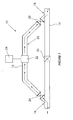
- an electricity generating arrangement 10 comprises a secondary water conduit 12, typically in the form of a pipe, fitted to a primary water conduit 14, which, again, is typically also in the form of a pipe.
- the secondary water pipe 12 defines an inlet 16 for allowing water flowing through the primary water pipe 14 to enter the secondary water pipe 12.
- the secondary water pipe 12 further defines an outlet 18 for allowing water flowing through the secondary water pipe 12 to exit the secondary water pipe 12 so as to rejoin the primary water pipe 14, as indicated by the arrows in the figure.
- the primary water pipe 14 includes a pressure reducing device, in the form of a pressure reducing valve 20, as is well known in the art.
- a rotatable turbine 22 is located within the secondary water pipe 12, the turbine 20 being connectable to a generator 24 so that under the influence of the water flowing through the secondary water pipe 12, the turbine 22 can rotate so as to drive the generator 24 to generate electricity for distribution or storage.
- an inlet valve 26 is located within the secondary water pipe 12, adjacent the inlet 16, and an outlet valve 28 is located within the secondary water pipe 12, adjacent the outlet 18.
- the valves 26, 28 may take the form of a non return valve and/or pressure reducing valve, depending on a number of factors, such as the size of supply and location, the water pressure and the anticipated water flow speed.
- one or more booster pumps may be fitted, if and when needed.
- the secondary water pipe 12 comprises a substantially elongate portion 30 that runs substantially parallel to the primary water pipe 14.
- the turbine 22 comprises either a fin arrangement or a threaded screw.
- the primary water pipe 14 is part of a residential/municipal water pipe system.
- the water pipe system may be part of a local government, government, semi-government or privately owned water distribution network.
- the primary water pipe is defined by anatural conduit carrying water, such as a river.
- pumps may be fitted to pump the water out of the river, through the secondary water pipe, and then back into the river.
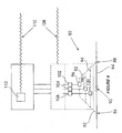
- FIG. 2 shows the relationship between the electricity generating arrangement 10 shown in Figure 1 and an electrical reticulation grid or network.
- Figure 2 shows the secondary water pipe 12, turbine 22 and generator 24, as described above.
- the generator 24 may be housed within a suitable power station 42, with connection cables 44 extending from the generator 24 to a transformer station 46.
- overhead cables 48 connect the transformer station 46 to a mast 50, and then from the mast 50 to another transformer station 52.
- a further overhead cable 54 may carry the electricity to another mast 56, which can then further distribute the electricity as needed.
- underground cables 58, 60 may also be used to carry the electricity to a transformer station 46 or 52, and then onto a mini substation or directly to a consumer.
- the reticulation network may be designed in any one of a number of well-known ways, with the grid shown in Figure 3 representing only one illustrative way of doing this.
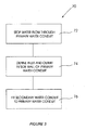
- This method 70 comprises stopping the flow of water through the primary water pipe, as indicated by block 72.
- the method 70 then comprises defining an outlet and an inlet in a side wall of the primary water pipe, as indicated by block 74.
- the method 70 concludes by fitting a secondary water pipe to the primary water pipe, as indicated by block 76.
- the secondary water pipe defines an inlet that can be in fluid communication with the outlet defined in the primary water pipe.
- the secondary water pipe further defines an outlet that can be in fluid communication with the inlet defined in the primary water pipe.
- the secondary water pipe houses a rotatable turbine, the turbine being connectable to a generator, so that water flowing through the primary water pipe can enter the secondary water pipe, flow through the secondary water pipe and exit the secondary water pipe so as to rejoin the primary water pipe, so that under the influence of the water flowing through the secondary water pipe, the turbine can rotate so as to drive the generator to generate electricity.
- the method includes fitting an inlet valve within the secondary water pipe, adjacent its inlet, and fitting an outlet valve within the secondary water pipe, adjacent its outlet.
- an electricity generating arrangement 80 comprises a main secondary water conduit 82, typically in the form of a pipe, fitted to a primary water conduit 84, which, again, is typically also in the form of a pipe.
- the main secondary water pipe 82 defines an inlet 86 for allowing water flowing through the primary water pipe 84 to enter the main secondary water pipe 82.
- the main secondary water pipe 82 further defines an outlet 88 for allowing water flowing through the main secondary water pipe 82 to exit the main secondary water pipe 82 so as to rejoin the primary water pipe 84, as described above.
- the primary water pipe 84 includes a pressure reducing device in the form of a pressure reducing valve 90, as is well known in the art.
- a plurality of additional secondary water conduits 92, 94 extend across the ends of the main secondary water pipe 82 so as to define a parallel arrangement of secondary water pipes 82, 92 and 94.
- Rotatable turbines 96, 98 and 100 are located within the secondary water pipes 82, 92 and 94, respectively. Each turbine 96, 98 and 100 is connectable to a generator 102, 104 and 106 so that under the influence of the water flowing through the secondary water pipes 82, 92 and 94 the turbines 96, 98 and 100 can rotate so as to drive the generators 102, 104 and 106 to generate electricity.
- the generated electricity may either be distributed locally via a local cable distribution network, as indicated by arrow 108, or the voltage may be stepped up using suitable transformers 110 for long distance distribution over a high voltage network, as indicated by arrow 112.
- an electricity generating arrangement 120 comprises replacing a pressure reducing device, which is typically fitted within a primary water conduit 122, with a rotatable turbine 124.
- the turbine 124 may then in turn be connected to a generator 126, so that water flowing through the primary water conduit can drive the generator 126 to generate electricity.
- the generated electricity may either be distributed locally via a local cable distribution network, as indicated by arrow 128, or the voltage may be stepped up using suitable transformers 130 for long distance distribution over a high voltage network, as indicated by arrow 132.
- a pressure reducing device such as a pressure reducing valve 134, may be fitted adjacent the primary water conduit 122, so as to be substantially in parallel with the rotatable turbine 124.
- a secondary/by-pass may be fitted in parallel with the primary water conduit 122, for use when the turbine 124 is not operational.
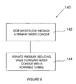
- a further aspect of the present invention provides a method 140 of fitting an electricity generating arrangement to a primary water conduit, the primary water conduit comprising a pressure reducing device.
- the method 140 comprises stopping the flow of water through the primary water conduit, as indicated by block 142, and then replacing the pressure reducing device within the primary water conduit with a rotatable turbine.
- the turbine is connectable to a generator, so that water flowing through the primary water conduit can drive the generator to generate electricity.
- the present invention discloses an electricity generating arrangement that is relatively quick, easy and inexpensive to setup.
Landscapes
- Engineering & Computer Science (AREA)
- General Engineering & Computer Science (AREA)
- Mechanical Engineering (AREA)
- Chemical & Material Sciences (AREA)
- Combustion & Propulsion (AREA)
- Civil Engineering (AREA)
- Power Engineering (AREA)
- Structural Engineering (AREA)
- Health & Medical Sciences (AREA)
- Life Sciences & Earth Sciences (AREA)
- Hydrology & Water Resources (AREA)
- Public Health (AREA)
- Water Supply & Treatment (AREA)
- Other Liquid Machine Or Engine Such As Wave Power Use (AREA)
- Hydraulic Turbines (AREA)
Claims (7)
- Anordnung zur Erzeugung von Elektrizität, welche umfasst:mindestens eine sekundäre Wasserleitung (12), die an einer primären Wasserleitung (14) angebracht ist, wobei die primäre Wasserleitung (14) mit einem Druckreduzierventil (20) ausgestattet ist, wobei die sekundäre Wasserleitung (12) einen Einlass (16) vor dem Druckreduzierventil (20) definiert, um zu ermöglichen, dass durch die primäre Wasserleitung (14) fließendes Wasser in die sekundäre Wasserleitung (12) eintritt, und einen Auslass (18), um zu ermöglichen, dass durch die sekundäre Wasserleitung (12) fließendes Wasser aus der sekundären Wasserleitung (12) austritt, so dass es nach dem Druckreduzierventil (20) wieder in die primäre Wasserleitung (14) eintritt, wobei der Strom von Wasser durch die sekundäre Wasserleitung (12) somit das Druckreduzierventil (20) der primären Wasserleitung (14) umgeht, wobei die sekundäre Wasserleitung (12) einen im Wesentlichen lang gestreckten Abschnitt (30) umfasst, welcher im Wesentlichen parallel zu der primären Wasserleitung (14) verläuft; undmindestens eine drehbare Turbine (22), die innerhalb der sekundären Wasserleitung (12) angeordnet ist, wobei jede Turbine (22) mit einem Generator (24) verbindbar ist, so dass unter dem Einfluss des durch die sekundäre Wasserleitung (12) fließenden Wassers die Turbine (22) rotieren kann, um den Generator (24) anzutreiben, um Elektrizität zu erzeugen.
- Anordnung zur Erzeugung von Elektrizität nach Anspruch 1, wobei ein Einlassventil (26) innerhalb der sekundären Wasserleitung (12), dem Einlass (16) benachbart, angeordnet ist und ein Auslassventil (28) innerhalb der sekundären Wasserleitung (12), dem Auslass (18) benachbart, angeordnet ist.
- Anordnung zur Erzeugung von Elektrizität nach einem der vorhergehenden Ansprüche, wobei die Turbine (22) entweder eine Rippenanordnung oder eine Gewindeschraube umfasst.
- Anordnung zur Erzeugung von Elektrizität nach einem der vorhergehenden Ansprüche, wobei die primäre Wasserleitung (14) Teil eines Haushalts-/kommunalen Wasserverteilungssystems ist.
- Anordnung zur Erzeugung von Elektrizität nach einem der Ansprüche 1 bis 3, wobei die primäre Wasserleitung (14) durch einen natürlichen wasserführenden Kanal definiert ist.
- Verfahren zur Installation einer Anordnung zur Erzeugung von Elektrizität an einer primären Wasserleitung (14), wobei die primäre Wasserleitung (14) mit einem Druckreduzierventil (20) ausgestattet ist, wobei das Verfahren umfasst:Stoppen des Flusses von Wasser durch die primäre Wasserleitung (14);Definieren eines Auslasses (18) und eines Einlasses (16) in einer Seitenwand der primären Wasserleitung (14), auf gegenüberliegenden Seiten des Druckreduzierventils (20); undAnbringen einer sekundären Wasserleitung (12) an der primären Wasserleitung (14), wobei die sekundäre Wasserleitung (12) einen im Wesentlichen lang gestreckten Abschnitt (30) umfasst, welcher im Wesentlichen parallel zu der primären Wasserleitung (14) verläuft, wobei die sekundäre Wasserleitung (12) einen Einlass (16) definiert, welcher in Fluidverbindung mit dem in der primären Wasserleitung (14) definierten Auslass (18) stehen kann, wobei die sekundäre Wasserleitung (12) einen Auslass (18) definiert, welcher in Fluidverbindung mit dem in der primären Wasserleitung (14) definierten Einlass (16) stehen kann, wobei in der sekundären Wasserleitung (12) eine drehbare Turbine (22) angeordnet ist, wobei die Turbine mit einem Generator (24) verbindbar ist,so dass durch die primäre Wasserleitung (14) fließendes Wasser in die sekundäre Wasserleitung (12) eintreten, durch die sekundäre Wasserleitung (12) fließen und aus der die sekundären Wasserleitung (12) austreten kann, so dass es wieder in die primäre Wasserleitung (14) eintritt, wobei es somit das Druckreduzierventil (20) der primären Wasserleitung (14) umgeht, so dass unter dem Einfluss des durch die sekundäre Wasserleitung (12) fließenden Wassers die Turbine (22) rotieren kann, um den Generator (24) anzutreiben, um Elektrizität zu erzeugen.
- Verfahren nach Anspruch 6, welches das Anbringen eines Einlassventils (26) innerhalb der sekundären Wasserleitung (12), ihrem Einlass (16) benachbart, und das Anbringen eines Auslassventils (28) innerhalb der sekundären Wasserleitung (12), ihrem Auslass (18) benachbart, beinhaltet.
Applications Claiming Priority (2)
| Application Number | Priority Date | Filing Date | Title |
|---|---|---|---|
| ZA200801762 | 2008-02-25 | ||
| PCT/IB2009/000277 WO2009106945A2 (en) | 2008-02-25 | 2009-02-17 | Electricity generating arrangement |
Publications (2)
| Publication Number | Publication Date |
|---|---|
| EP2279344A2 EP2279344A2 (de) | 2011-02-02 |
| EP2279344B1 true EP2279344B1 (de) | 2013-04-24 |
Family
ID=41016520
Family Applications (1)
| Application Number | Title | Priority Date | Filing Date |
|---|---|---|---|
| EP09714497.6A Not-in-force EP2279344B1 (de) | 2008-02-25 | 2009-02-17 | Anordnung zur erzeugung von elektrizität |
Country Status (4)
| Country | Link |
|---|---|
| US (1) | US20110006530A1 (de) |
| EP (1) | EP2279344B1 (de) |
| WO (1) | WO2009106945A2 (de) |
| ZA (1) | ZA200901070B (de) |
Families Citing this family (14)
| Publication number | Priority date | Publication date | Assignee | Title |
|---|---|---|---|---|
| US20120086204A1 (en) * | 2010-10-11 | 2012-04-12 | Cla-Val Co. | System and method for controlled hydroelectric power generation |
| ITTO20100993A1 (it) * | 2010-12-14 | 2012-06-15 | Welt Company S R L | Sistema per la generazione di energia idroelettrica |
| GB2507044A (en) * | 2012-10-16 | 2014-04-23 | May Gurney Ltd | Pipeline turbine with pressure and flow control |
| CN107076102B (zh) * | 2014-10-23 | 2019-05-07 | 大金工业株式会社 | 流体系统 |
| WO2016185256A1 (en) * | 2015-05-21 | 2016-11-24 | Khachan Mohammad | Closed-circuit hot water piping system capable to reduce water consumption at a low cost |
| ITUA20161469A1 (it) * | 2016-03-08 | 2017-09-08 | Giorgio Filippini | Dispositivo per il rilevamento e l’intercettazione di dispersioni di fluidi |
| JP6421850B2 (ja) * | 2016-09-20 | 2018-11-14 | ダイキン工業株式会社 | 水力発電システム |
| ES2927707T3 (es) * | 2016-09-20 | 2022-11-10 | Daikin Ind Ltd | Sistema de generación de energía hidroeléctrica |
| FR3073335B1 (fr) * | 2017-11-06 | 2019-10-04 | Marc Vanbaleghem | Installation de recharge de vehicules electriques equipee d'une turbogeneratrice exploitant les reseaux de fluides |
| IT201800009417A1 (it) * | 2018-10-12 | 2020-04-12 | Sws Eng Spa | Impianto idrico a soglia di sfioro |
| US11946604B2 (en) | 2020-10-26 | 2024-04-02 | InPipe Energy, Inc. | Pipeline energy recovery system |
| US11242836B2 (en) | 2020-04-06 | 2022-02-08 | BGH Designs, LLC | Apparatuses, systems, and methods for providing power generation |
| US12104568B2 (en) | 2020-04-06 | 2024-10-01 | BGH Designs, LLC | Apparatuses, systems, and methods for providing power generation |
| FR3111396B1 (fr) * | 2020-06-16 | 2022-12-30 | Consomix | Dispositif de conversion d’énergie, générateur d’energie electrique, système |
Family Cites Families (15)
| Publication number | Priority date | Publication date | Assignee | Title |
|---|---|---|---|---|
| US716650A (en) * | 1902-01-15 | 1902-12-23 | Milo L G Wheeler | Water-motor. |
| US1726405A (en) * | 1927-11-28 | 1929-08-27 | Samuel B Mchenry | Current motor |
| CH610058A5 (en) * | 1975-11-05 | 1979-03-30 | Ernst Gasser | Hydraulic engine with generators driven by it |
| US4241283A (en) * | 1978-09-05 | 1980-12-23 | Storer Richard R Sr | Hydro-electric power plant |
| JPS5717204A (en) | 1980-07-04 | 1982-01-28 | Fujitsu Ltd | Transient sound prevention type power amplifying circuit |
| JPS5717024A (en) * | 1980-07-04 | 1982-01-28 | Hitachi Ltd | Discharge flow rate automatic control method for motive power recovering device |
| US4352025A (en) * | 1980-11-17 | 1982-09-28 | Troyen Harry D | System for generation of electrical power |
| JPS6047883A (ja) * | 1983-08-26 | 1985-03-15 | Masao Kinemura | 自然流下パイプラインに付帯させる発電装置 |
| DE3800192A1 (de) * | 1987-02-02 | 1988-08-11 | Karl Wilhelm Schneider | Unterschlaegige wasserradanordnung |
| US5140254A (en) * | 1990-10-10 | 1992-08-18 | David Katzman | Shower accessory |
| US6765308B1 (en) * | 2002-04-22 | 2004-07-20 | Harry Kazanjian | Hydro-energy conversion system |
| DE202004003596U1 (de) * | 2004-03-09 | 2004-05-27 | Kümmerle, Detlef | Modulkombination zur Ausnutzung regenerativer Energie |
| JP3763022B2 (ja) * | 2004-03-18 | 2006-04-05 | 株式会社カクダイ | 水力発電装置および該装置を備えた給水システム |
| US7084521B1 (en) * | 2005-02-17 | 2006-08-01 | Martin Gerald G | Method and apparatus for generating hydro-electric power |
| US7357599B2 (en) * | 2005-08-10 | 2008-04-15 | Criptonic Energy Solutions, Inc. | Waste water electrical power generating system |
-
2009
- 2009-02-16 ZA ZA200901070A patent/ZA200901070B/en unknown
- 2009-02-17 EP EP09714497.6A patent/EP2279344B1/de not_active Not-in-force
- 2009-02-17 US US12/919,297 patent/US20110006530A1/en not_active Abandoned
- 2009-02-17 WO PCT/IB2009/000277 patent/WO2009106945A2/en not_active Ceased
Also Published As
| Publication number | Publication date |
|---|---|
| WO2009106945A4 (en) | 2010-09-23 |
| WO2009106945A2 (en) | 2009-09-03 |
| US20110006530A1 (en) | 2011-01-13 |
| ZA200901070B (en) | 2009-06-24 |
| WO2009106945A3 (en) | 2010-07-29 |
| EP2279344A2 (de) | 2011-02-02 |
Similar Documents
| Publication | Publication Date | Title |
|---|---|---|
| EP2279344B1 (de) | Anordnung zur erzeugung von elektrizität | |
| US10344741B2 (en) | Hydro-pneumatic energy storage system | |
| Casini | Harvesting energy from in-pipe hydro systems at urban and building scale | |
| Kusakana | A survey of innovative technologies increasing the viability of micro-hydropower as a cost effective rural electrification option in South Africa | |
| US9800054B2 (en) | DC connection system for renewable power generators | |
| Cazzaniga et al. | DOGES: deep ocean gravitational energy storage | |
| CN202023678U (zh) | 一种自来水厂管道势能发电系统 | |
| Suman et al. | Electricity generation through water supply pipes in high rise buildings | |
| Saket | Design, development and reliability evaluation of micro hydro power generation system based on municipal waste water | |
| US7501712B2 (en) | Process for using waste water from community sewer systems to generate electrical power | |
| KR20060120873A (ko) | 수력발전기 시스템 | |
| JPS6047883A (ja) | 自然流下パイプラインに付帯させる発電装置 | |
| KR101088381B1 (ko) | 수도관의 수압차를 이용한 마이크로 발전장치 | |
| Arabali et al. | Steady-state operation and control of an in-conduit hydro-powered generator | |
| Suryatna et al. | Prototype design of waterwheel micro hydro power plants for small water discharge | |
| CN111720744A (zh) | 管网余压能量利用装置和节能管网 | |
| Levine | Pumped hydroelectric energy storage | |
| Sammartano et al. | Coupled hydraulic and electronic regulation for Banki turbines | |
| JP4597257B1 (ja) | 水力発電システム | |
| KIM et al. | Power generation system for using unused energy in district heating pipelines | |
| KR200396776Y1 (ko) | 수력발전기 시스템 | |
| RU69089U1 (ru) | Утилизационная гидроэлектростанция | |
| US20160268810A1 (en) | Pylon based power management system | |
| ITTO20100993A1 (it) | Sistema per la generazione di energia idroelettrica | |
| Darmawan et al. | Renewable Energy Offshore: The Front-End Engineering Design of a Solar-Powered Unmanned Wellhead Platform |
Legal Events
| Date | Code | Title | Description |
|---|---|---|---|
| PUAI | Public reference made under article 153(3) epc to a published international application that has entered the european phase |
Free format text: ORIGINAL CODE: 0009012 |
|
| 17P | Request for examination filed |
Effective date: 20100921 |
|
| AK | Designated contracting states |
Kind code of ref document: A2 Designated state(s): AT BE BG CH CY CZ DE DK EE ES FI FR GB GR HR HU IE IS IT LI LT LU LV MC MK MT NL NO PL PT RO SE SI SK TR |
|
| DAX | Request for extension of the european patent (deleted) | ||
| 17Q | First examination report despatched |
Effective date: 20110617 |
|
| GRAP | Despatch of communication of intention to grant a patent |
Free format text: ORIGINAL CODE: EPIDOSNIGR1 |
|
| GRAS | Grant fee paid |
Free format text: ORIGINAL CODE: EPIDOSNIGR3 |
|
| GRAA | (expected) grant |
Free format text: ORIGINAL CODE: 0009210 |
|
| AK | Designated contracting states |
Kind code of ref document: B1 Designated state(s): AT BE BG CH CY CZ DE DK EE ES FI FR GB GR HR HU IE IS IT LI LT LU LV MC MK MT NL NO PL PT RO SE SI SK TR |
|
| REG | Reference to a national code |
Ref country code: GB Ref legal event code: FG4D |
|
| REG | Reference to a national code |
Ref country code: CH Ref legal event code: EP |
|
| REG | Reference to a national code |
Ref country code: AT Ref legal event code: REF Ref document number: 608775 Country of ref document: AT Kind code of ref document: T Effective date: 20130515 |
|
| REG | Reference to a national code |
Ref country code: IE Ref legal event code: FG4D |
|
| REG | Reference to a national code |
Ref country code: DE Ref legal event code: R096 Ref document number: 602009015212 Country of ref document: DE Effective date: 20130620 |
|
| REG | Reference to a national code |
Ref country code: AT Ref legal event code: MK05 Ref document number: 608775 Country of ref document: AT Kind code of ref document: T Effective date: 20130424 |
|
| REG | Reference to a national code |
Ref country code: LT Ref legal event code: MG4D |
|
| REG | Reference to a national code |
Ref country code: NL Ref legal event code: VDEP Effective date: 20130424 |
|
| PG25 | Lapsed in a contracting state [announced via postgrant information from national office to epo] |
Ref country code: FI Free format text: LAPSE BECAUSE OF FAILURE TO SUBMIT A TRANSLATION OF THE DESCRIPTION OR TO PAY THE FEE WITHIN THE PRESCRIBED TIME-LIMIT Effective date: 20130424 Ref country code: NO Free format text: LAPSE BECAUSE OF FAILURE TO SUBMIT A TRANSLATION OF THE DESCRIPTION OR TO PAY THE FEE WITHIN THE PRESCRIBED TIME-LIMIT Effective date: 20130724 Ref country code: SE Free format text: LAPSE BECAUSE OF FAILURE TO SUBMIT A TRANSLATION OF THE DESCRIPTION OR TO PAY THE FEE WITHIN THE PRESCRIBED TIME-LIMIT Effective date: 20130424 Ref country code: GR Free format text: LAPSE BECAUSE OF FAILURE TO SUBMIT A TRANSLATION OF THE DESCRIPTION OR TO PAY THE FEE WITHIN THE PRESCRIBED TIME-LIMIT Effective date: 20130725 Ref country code: LT Free format text: LAPSE BECAUSE OF FAILURE TO SUBMIT A TRANSLATION OF THE DESCRIPTION OR TO PAY THE FEE WITHIN THE PRESCRIBED TIME-LIMIT Effective date: 20130424 Ref country code: IS Free format text: LAPSE BECAUSE OF FAILURE TO SUBMIT A TRANSLATION OF THE DESCRIPTION OR TO PAY THE FEE WITHIN THE PRESCRIBED TIME-LIMIT Effective date: 20130824 Ref country code: BE Free format text: LAPSE BECAUSE OF FAILURE TO SUBMIT A TRANSLATION OF THE DESCRIPTION OR TO PAY THE FEE WITHIN THE PRESCRIBED TIME-LIMIT Effective date: 20130424 Ref country code: AT Free format text: LAPSE BECAUSE OF FAILURE TO SUBMIT A TRANSLATION OF THE DESCRIPTION OR TO PAY THE FEE WITHIN THE PRESCRIBED TIME-LIMIT Effective date: 20130424 Ref country code: SI Free format text: LAPSE BECAUSE OF FAILURE TO SUBMIT A TRANSLATION OF THE DESCRIPTION OR TO PAY THE FEE WITHIN THE PRESCRIBED TIME-LIMIT Effective date: 20130424 Ref country code: ES Free format text: LAPSE BECAUSE OF FAILURE TO SUBMIT A TRANSLATION OF THE DESCRIPTION OR TO PAY THE FEE WITHIN THE PRESCRIBED TIME-LIMIT Effective date: 20130804 Ref country code: PT Free format text: LAPSE BECAUSE OF FAILURE TO SUBMIT A TRANSLATION OF THE DESCRIPTION OR TO PAY THE FEE WITHIN THE PRESCRIBED TIME-LIMIT Effective date: 20130826 |
|
| PG25 | Lapsed in a contracting state [announced via postgrant information from national office to epo] |
Ref country code: LV Free format text: LAPSE BECAUSE OF FAILURE TO SUBMIT A TRANSLATION OF THE DESCRIPTION OR TO PAY THE FEE WITHIN THE PRESCRIBED TIME-LIMIT Effective date: 20130424 Ref country code: BG Free format text: LAPSE BECAUSE OF FAILURE TO SUBMIT A TRANSLATION OF THE DESCRIPTION OR TO PAY THE FEE WITHIN THE PRESCRIBED TIME-LIMIT Effective date: 20130724 Ref country code: CY Free format text: LAPSE BECAUSE OF FAILURE TO SUBMIT A TRANSLATION OF THE DESCRIPTION OR TO PAY THE FEE WITHIN THE PRESCRIBED TIME-LIMIT Effective date: 20130424 Ref country code: HR Free format text: LAPSE BECAUSE OF FAILURE TO SUBMIT A TRANSLATION OF THE DESCRIPTION OR TO PAY THE FEE WITHIN THE PRESCRIBED TIME-LIMIT Effective date: 20130424 Ref country code: PL Free format text: LAPSE BECAUSE OF FAILURE TO SUBMIT A TRANSLATION OF THE DESCRIPTION OR TO PAY THE FEE WITHIN THE PRESCRIBED TIME-LIMIT Effective date: 20130424 |
|
| PG25 | Lapsed in a contracting state [announced via postgrant information from national office to epo] |
Ref country code: EE Free format text: LAPSE BECAUSE OF FAILURE TO SUBMIT A TRANSLATION OF THE DESCRIPTION OR TO PAY THE FEE WITHIN THE PRESCRIBED TIME-LIMIT Effective date: 20130424 Ref country code: DK Free format text: LAPSE BECAUSE OF FAILURE TO SUBMIT A TRANSLATION OF THE DESCRIPTION OR TO PAY THE FEE WITHIN THE PRESCRIBED TIME-LIMIT Effective date: 20130424 Ref country code: CZ Free format text: LAPSE BECAUSE OF FAILURE TO SUBMIT A TRANSLATION OF THE DESCRIPTION OR TO PAY THE FEE WITHIN THE PRESCRIBED TIME-LIMIT Effective date: 20130424 Ref country code: SK Free format text: LAPSE BECAUSE OF FAILURE TO SUBMIT A TRANSLATION OF THE DESCRIPTION OR TO PAY THE FEE WITHIN THE PRESCRIBED TIME-LIMIT Effective date: 20130424 |
|
| PG25 | Lapsed in a contracting state [announced via postgrant information from national office to epo] |
Ref country code: NL Free format text: LAPSE BECAUSE OF FAILURE TO SUBMIT A TRANSLATION OF THE DESCRIPTION OR TO PAY THE FEE WITHIN THE PRESCRIBED TIME-LIMIT Effective date: 20130424 Ref country code: RO Free format text: LAPSE BECAUSE OF FAILURE TO SUBMIT A TRANSLATION OF THE DESCRIPTION OR TO PAY THE FEE WITHIN THE PRESCRIBED TIME-LIMIT Effective date: 20130424 |
|
| PLBE | No opposition filed within time limit |
Free format text: ORIGINAL CODE: 0009261 |
|
| STAA | Information on the status of an ep patent application or granted ep patent |
Free format text: STATUS: NO OPPOSITION FILED WITHIN TIME LIMIT |
|
| 26N | No opposition filed |
Effective date: 20140127 |
|
| REG | Reference to a national code |
Ref country code: DE Ref legal event code: R097 Ref document number: 602009015212 Country of ref document: DE Effective date: 20140127 |
|
| REG | Reference to a national code |
Ref country code: DE Ref legal event code: R119 Ref document number: 602009015212 Country of ref document: DE |
|
| PG25 | Lapsed in a contracting state [announced via postgrant information from national office to epo] |
Ref country code: LU Free format text: LAPSE BECAUSE OF FAILURE TO SUBMIT A TRANSLATION OF THE DESCRIPTION OR TO PAY THE FEE WITHIN THE PRESCRIBED TIME-LIMIT Effective date: 20140217 Ref country code: MC Free format text: LAPSE BECAUSE OF FAILURE TO SUBMIT A TRANSLATION OF THE DESCRIPTION OR TO PAY THE FEE WITHIN THE PRESCRIBED TIME-LIMIT Effective date: 20130424 |
|
| REG | Reference to a national code |
Ref country code: CH Ref legal event code: PL |
|
| GBPC | Gb: european patent ceased through non-payment of renewal fee |
Effective date: 20140217 |
|
| PG25 | Lapsed in a contracting state [announced via postgrant information from national office to epo] |
Ref country code: LI Free format text: LAPSE BECAUSE OF NON-PAYMENT OF DUE FEES Effective date: 20140228 Ref country code: CH Free format text: LAPSE BECAUSE OF NON-PAYMENT OF DUE FEES Effective date: 20140228 |
|
| REG | Reference to a national code |
Ref country code: FR Ref legal event code: ST Effective date: 20141031 |
|
| REG | Reference to a national code |
Ref country code: IE Ref legal event code: MM4A |
|
| REG | Reference to a national code |
Ref country code: DE Ref legal event code: R119 Ref document number: 602009015212 Country of ref document: DE Effective date: 20140902 |
|
| PG25 | Lapsed in a contracting state [announced via postgrant information from national office to epo] |
Ref country code: IE Free format text: LAPSE BECAUSE OF NON-PAYMENT OF DUE FEES Effective date: 20140217 Ref country code: DE Free format text: LAPSE BECAUSE OF NON-PAYMENT OF DUE FEES Effective date: 20140902 Ref country code: GB Free format text: LAPSE BECAUSE OF NON-PAYMENT OF DUE FEES Effective date: 20140217 Ref country code: FR Free format text: LAPSE BECAUSE OF NON-PAYMENT OF DUE FEES Effective date: 20140228 |
|
| PG25 | Lapsed in a contracting state [announced via postgrant information from national office to epo] |
Ref country code: MT Free format text: LAPSE BECAUSE OF FAILURE TO SUBMIT A TRANSLATION OF THE DESCRIPTION OR TO PAY THE FEE WITHIN THE PRESCRIBED TIME-LIMIT Effective date: 20130424 |
|
| PG25 | Lapsed in a contracting state [announced via postgrant information from national office to epo] |
Ref country code: IT Free format text: LAPSE BECAUSE OF NON-PAYMENT OF DUE FEES Effective date: 20140217 |
|
| PG25 | Lapsed in a contracting state [announced via postgrant information from national office to epo] |
Ref country code: TR Free format text: LAPSE BECAUSE OF FAILURE TO SUBMIT A TRANSLATION OF THE DESCRIPTION OR TO PAY THE FEE WITHIN THE PRESCRIBED TIME-LIMIT Effective date: 20130424 Ref country code: HU Free format text: LAPSE BECAUSE OF FAILURE TO SUBMIT A TRANSLATION OF THE DESCRIPTION OR TO PAY THE FEE WITHIN THE PRESCRIBED TIME-LIMIT; INVALID AB INITIO Effective date: 20090217 |
|
| PG25 | Lapsed in a contracting state [announced via postgrant information from national office to epo] |
Ref country code: MK Free format text: LAPSE BECAUSE OF FAILURE TO SUBMIT A TRANSLATION OF THE DESCRIPTION OR TO PAY THE FEE WITHIN THE PRESCRIBED TIME-LIMIT Effective date: 20130424 |