EP2279489B1 - Maschenkollisionsvermeidung - Google Patents
Maschenkollisionsvermeidung Download PDFInfo
- Publication number
- EP2279489B1 EP2279489B1 EP09730313.5A EP09730313A EP2279489B1 EP 2279489 B1 EP2279489 B1 EP 2279489B1 EP 09730313 A EP09730313 A EP 09730313A EP 2279489 B1 EP2279489 B1 EP 2279489B1
- Authority
- EP
- European Patent Office
- Prior art keywords
- mesh
- feature
- image data
- candidate
- region
- Prior art date
- Legal status (The legal status is an assumption and is not a legal conclusion. Google has not performed a legal analysis and makes no representation as to the accuracy of the status listed.)
- Active
Links
Images



Classifications
-
- G—PHYSICS
- G06—COMPUTING OR CALCULATING; COUNTING
- G06T—IMAGE DATA PROCESSING OR GENERATION, IN GENERAL
- G06T7/00—Image analysis
- G06T7/10—Segmentation; Edge detection
- G06T7/11—Region-based segmentation
-
- G—PHYSICS
- G06—COMPUTING OR CALCULATING; COUNTING
- G06T—IMAGE DATA PROCESSING OR GENERATION, IN GENERAL
- G06T2207/00—Indexing scheme for image analysis or image enhancement
- G06T2207/10—Image acquisition modality
- G06T2207/10072—Tomographic images
-
- G—PHYSICS
- G06—COMPUTING OR CALCULATING; COUNTING
- G06T—IMAGE DATA PROCESSING OR GENERATION, IN GENERAL
- G06T2207/00—Indexing scheme for image analysis or image enhancement
- G06T2207/10—Image acquisition modality
- G06T2207/10116—X-ray image
-
- G—PHYSICS
- G06—COMPUTING OR CALCULATING; COUNTING
- G06T—IMAGE DATA PROCESSING OR GENERATION, IN GENERAL
- G06T2207/00—Indexing scheme for image analysis or image enhancement
- G06T2207/30—Subject of image; Context of image processing
- G06T2207/30004—Biomedical image processing
- G06T2207/30008—Bone
- G06T2207/30012—Spine; Backbone
Definitions
- the invention relates to image segmentation and more particularly to simultaneous model-based segmentation of multiple objects in image data.
- Model-based segmentation has numerous applications in interventions and follow-up studies, for instance in radiation therapy planning.
- Deformable models described by flexible meshes, for instance triangle meshes or simplex meshes, are adapted to the corresponding image structures. Usually this adaptation is carried out for every object separately by optimizing a weighted sum of two competing energies: an external energy driving the mesh triangles towards features in the image, and an internal energy preserving the form of the model.
- An implementation of this method is described by J. Weese, M. Kaus, C. Lorenz, S. Lobregt, R. Truyen, V. Pekar in "Shape constrained deformable models for 3D medical Image segmentation", IPMI 2001, 3pp. 80-387 , hereinafter referred to as Ref. 1.
- a region of image data which should not overlap with a mesh adapted to an object in the image data may not be defined by another mesh.
- the region to be avoided may be defined by a plane separating the right hemisphere from the left hemisphere.
- the region to be avoided may be defined by a sphere comprising the nodule.
- the invention provides a system for segmenting an object in image data using model-based image segmentation as defined in claim 1.
- Determining whether a selected candidate feature is located inside the region which should be avoided, e.g., inside another mesh adapted to another object in the image data, allows penalizing this candidate feature during the computation of the strength of each feature and thus during the evaluation of the plurality of candidate features. For example, this can be achieved by decreasing the feature strength such that the evaluation unit is more likely to select a candidate feature outside the region.
- the invention helps identifying the right image feature from the plurality of candidate features. However, if a prominent candidate feature of the image is found inside the region, it may still be taken into account.
- finding a prominent feature inside the other mesh may indicate that the other mesh is not well adapted to the other object.
- Employing an algorithm that iteratively adapts the other mesh to the other object in the image data while penalizing candidate features located inside the mesh may result in that the other mesh is repelled from the region defined by the adapted mesh, thereby avoiding a collision (i.e. an overlap) of the two meshes.
- system further comprises:
- the strength of each of the candidate features inside the region is a function of the distance from the corresponding candidate feature inside the region to a boundary of the region.
- the strength of the candidate feature may be a product, wherein a factor of this product depends on the distance from the candidate feature inside the region to a boundary of the region. This provides an easy and yet versatile way of taking into account effects of the position of the candidate feature relative to the region on the strength of the feature.
- the region boundary is defined by a mesh adapted to a second object in the image data.
- the invention is thus adapted to simultaneous adaptation of multiple objects in the image data.
- the strength of each of the candidate features inside the region substantially decreases with the distance from the corresponding candidate feature inside the region to the boundary of the region.
- Candidate features deep inside the region are thus heavier penalized than candidate features close to the boundary of the region.
- the system is used for segmenting a plurality of objects in image data by adapting a mesh to each object of the plurality of objects, wherein, during adaptation of a certain mesh to a certain object of the plurality of objects, the region is defined based on current positions of meshes adapted to objects of the plurality of objects other than said certain mesh.
- the system may be arranged to detect and possibly prevent overlap of multiple meshes used for segmenting a plurality of objects in the image data.
- system according to the invention is comprised in an image acquisition apparatus.
- the invention provides a method of segmenting an object in image data using model-based image segmentation as defined in claim 8.
- the invention provides a computer program product to be loaded by a computer arrangement, the computer program comprising instructions for segmenting an object in image data using model-based image segmentation, said instructions further comprising instructions for identifying features in the image data for computing an external energy of a mesh on the basis of a current position of the mesh, the computer arrangement comprising a processing unit and a memory, the computer program product, after being loaded, providing said processing unit with the capability to carry out steps of the method.
- multidimensional image data e.g., 2-dimensional (2-D), 3-dimensional (3-D) or 4-dimensional (4-D) images
- acquisition modalities such as, but not limited to, X-ray Imaging, Computed Tomography (CT), Magnetic Resonance Imaging (MRI), Ultrasound (US), Positron Emission Tomography (PET), Single Photon Emission Computed Tomography (SPECT), and Nuclear Medicine (NM).
- CT Computed Tomography
- MRI Magnetic Resonance Imaging
- US Ultrasound
- PET Positron Emission Tomography
- SPECT Single Photon Emission Computed Tomography
- NM Nuclear Medicine
- Fig. 1 schematically shows a block diagram of an exemplary embodiment of the system 100 for segmenting an object in image data using model-based image segmentation, the system comprising a feature unit 120 for identifying features in the image data for computing an external energy of a mesh on the basis of a current position of the mesh, wherein the feature unit 120 further comprises:
- the exemplary embodiment of the system 100 further comprises the following units:
- the first input connector 181 is arranged to receive data coming in from a data storage means such as, but not limited to, a hard disk, a magnetic tape, a flash memory, or an optical disk.
- the second input connector 182 is arranged to receive data coming in from a user input device such as, but not limited to, a mouse or a touch screen.
- the third input connector 183 is arranged to receive data coming in from a user input device such as a keyboard.
- the input connectors 181, 182 and 183 are connected to an input control unit 180.
- the first output connector 191 is arranged to output the data to a data storage means such as a hard disk, a magnetic tape, a flash memory, or an optical disk.
- the second output connector 192 is arranged to output the data to a display device.
- the output connectors 191 and 192 receive the respective data via an output control unit 190.
- a person skilled in the art will understand that there are many ways to connect input devices to the input connectors 181, 182 and 183 and the output devices to the output connectors 191 and 192 of the system 100. These ways comprise, but are not limited to, a wired and a wireless connection, a digital network such as, but not limited to, a Local Area Network (LAN) and a Wide Area Network (WAN), the Internet, a digital telephone network, and an analog telephone network.
- LAN Local Area Network
- WAN Wide Area Network
- the system 100 comprises a memory unit 170.
- the system 100 is arranged to receive input data from external devices via any of the input connectors 181, 182, and 183 and to store the received input data in the memory unit 170. Loading the input data into the memory unit 170 allows quick access to relevant data portions by the units of the system 100.
- the input data may comprise, for example, the image data and model data, the model data comprising mesh data and region data.
- the memory unit 170 may be implemented by devices such as, but not limited to, a Random Access Memory (RAM) chip, a Read Only Memory (ROM) chip, and/or a hard disk drive and a hard disk.
- the memory unit 170 may be further arranged to store the output data.
- the output data may comprise, for example, the current position of the mesh adapted to the object of the plurality of objects.
- the memory unit 170 may be also arranged to receive data from and/or deliver data to the units of the system 100 comprising the pre-positioning unit 110, the feature unit 120, the transformation unit 130, the adaptation unit 140, the control unit 160, and the user interface 165, via a memory bus 175.
- the memory unit 170 is further arranged to make the output data available to external devices via any of the output connectors 191 and 192. Storing data from the units of the system 100 in the memory unit 170 may advantageously improve performance of the units of the system 100 as well as the rate of transfer of the output data from the units of the system 100 to external devices.
- the system 100 may comprise no memory unit 170 and no memory bus 175.
- the input data used by the system 100 may be supplied by at least one external device, such as an external memory or a processor, connected to the units of the system 100.
- the output data produced by the system 100 may be supplied to at least one external device, such as an external memory or a processor, connected to the units of the system 100.
- the units of the system 100 may be arranged to receive the data from each other via internal connections or via a data bus.
- the system 100 comprises a user interface 165 for communication between a user and the system 100.
- the user interface 165 may be arranged to receive a user input for selecting the mesh for adapting to the object in the image data or a user input for defining the region.
- the user interface may further provide means for displaying a view of the mesh adapted to the object.
- the user interface may receive a user input for selecting a mode of operation of the system such as, e.g., for defining the terms of the external or internal energy, or a pre-positioning method.
- a mode of operation of the system such as, e.g., for defining the terms of the external or internal energy, or a pre-positioning method.
- the pre-positioning unit 110 of the system 100 is arranged for pre-positioning a mesh close to the corresponding object.
- Pre-positioning may be manual or automatic and may involve detecting the first and second object.
- a method of detecting objects is described, for example, in " Towards fully automatic object detection and segmentation", Hauke Schramm et al., Proc. SPIE, Volume 6144, 614402 , Medical Imaging 2006: Image Processing; Joseph M. Reinhardt, Josien P. Pluim; Eds., pp. 11-20 .
- Pre-positioning the mesh yields an initialized current position of the mesh.
- the current position of the mesh can be defined by coordinates of each vertex of the mesh in a system of coordinates, e.g. the image data system of coordinates.
- the feature unit 120 is arranged for carrying out a search for image features in the image data.
- the search of each image feature is based on the current position of the mesh.
- the mesh is a triangular mesh to be adapted to the surface of the object.
- a feature is identified for each triangle of the mesh.
- the object surface detection is based on the method described in Section 2.1 of Ref. 1.
- the candidate feature unit 122 is arranged for selecting n candidate features in the image data.
- the position unit 124 is arranged for determining a position of each candidate feature relative to the region of the image data.
- the position unit 124 may be arranged for computing the distance d i from each candidate feature located inside the region to the region boundary.
- the feature function unit 126 is arranged for computing the strength F i * of each candidate feature, wherein the strength F i * of the candidate feature depends on the position of each candidate feature relative to the region.
- the factor c i is set to 1 if the corresponding feature is not inside the region. If the corresponding feature is inside the region, then the following holds: the larger the distance d i - the smaller is the factor c i .
- , and g max is a gradient threshold.
- the evaluation unit 128 is arranged for evaluating each candidate feature and for identifying the feature among the plurality of candidate features based on this evaluation.
- the evaluation unit 128 is arranged for selecting the candidate feature with the greatest strength F i * .
- Candidate features which are distant from the barycenter of the corresponding triangle may be additionally penalized.
- the evaluation unit 128 may be arranged to select the candidate feature which corresponds to the maximum of the sum F i * ⁇ ⁇
- the transformation unit 130 of the system 100 is arranged for computing a transformation which best aligns the mesh in the mesh current position with the pre-positioned mesh.
- the transformation is typically constrained to a certain class of transformations, e.g., to similarity transformations or to affine transformations (without reflections).
- An implementation of computing the transformation which best aligns the mesh in the mesh current position with the corresponding pre-positioned mesh is described in Sections 2.3 and 2.4 of Ref. 1.
- the current position of the mesh is updated by the adaptation unit 140 for updating current positions of vertices of the mesh to minimize a weighted sum of at least the external energy and an internal energy of every mesh.
- ⁇ and ⁇ are weights of the energy contributions.
- the external energy E ext is computed as described in Section 2.2 of Ref. 1.
- the control unit 160 of the system 100 is arranged for evaluating a convergence condition dependent at least on the minimized weighted sum or on the updated current position of the mesh, and further for terminating the segmentation if the condition is satisfied and for continuing the segmentation if the condition is not satisfied.
- An exemplary condition may be that "the number of updates of the current positions of the mesh reached a maximum or the current position has not significantly changed during the last update or the computed weighted sum of energies is less than a predetermined threshold".
- the system 100 may be used for segmenting a plurality of objects in image data by adapting a mesh to each object of the plurality of objects, wherein, during adaptation of a certain mesh to a certain object of the plurality of objects, the region is defined based on current positions of meshes adapted to objects of the plurality of objects other than the certain mesh.
- multiple meshes are pre-positioned to delineate a plurality of objects in the image data. Thereby, the current positions of the multiple meshes are initialized. A first mesh of the multiple meshes is then selected for adaptation to a first object of the plurality of objects. The area covered by the remaining meshes defines the region not to be overlapped by the selected mesh.
- a second mesh is selected for adaptation to a second object of the plurality of objects. Again, the area covered by the remaining meshes defines the region not to be overlapped by the second mesh, while the second mesh is adapted to the second object.
- the process continues until a mesh is adapted to each object of the plurality of objects.
- a convergence condition is evaluated. If the condition is satisfied, the segmentation is terminated. Otherwise, the segmentation continues with adapting the first mesh to the first object, the second mesh to the second object, and so on.
- the convergence condition may be that new mesh vertex coordinates do not differ significantly from the previous ones or that a maximum number of multiple mesh adaptations to the plurality of objects has been carried out.
- Fig. 2 shows an example of a medical application of the system 100.
- the third, fourth and fifth thoracic vertebrae are to be segmented.
- a pre-positioning of the three meshes is shown in the second image 22.
- the transition from bone cortex to marrow is comparable to the bone boundary; hence a separate adaptation of each vertebra is likely to fail as illustrated in the third image 23.
- Using the feature identification of the invention successfully preserves the spatial relationship of the vertebral meshes and hence results in a reasonable segmentation as illustrated in the fourth image 24.
- the system of the invention may be applied to detect mesh self-collision, when a candidate feature is located inside the mesh under adaptation.
- the region must include a part of the area defined by the mesh to be adapted. This option may be especially useful for segmenting long flexible structures such as blood vessels, for example.
- system 100 may be a valuable tool for assisting a physician in many aspects of her/his job. Further, although the embodiments of the system are illustrated using medical applications of the system, non-medical applications of the system are also contemplated.
- the units of the system 100 may be implemented using a processor. Normally, their functions are performed under the control of a software program product. During execution, the software program product is normally loaded into a memory, like a RAM, and executed from there. The program may be loaded from a background memory, such as a ROM, hard disk, or magnetic and/or optical storage, or may be loaded via a network like the Internet. Optionally, an application-specific integrated circuit may provide the described functionality.
- Fig. 3 shows a flowchart of an exemplary implementation of the method 300 of segmenting an object in image data using model-based image segmentation.
- the flowchart shows identifying one feature, e.g., for one face of a triangular mesh.
- the method 300 begins with candidate feature step 322 for selecting a plurality of candidate features in the image data, for identifying a feature to be included in the features identified in the image data.
- the method 300 continues to a position step 324 for determining a position of each candidate feature of the plurality of the candidate features relative to a region of the image data.
- the method 300 continues to a feature function step 326 for computing the strength of each candidate feature, wherein the strength of each candidate feature depends on the position of each candidate feature relative to the region.
- the method 300 continues to an evaluation step 328 for evaluating each candidate feature of the plurality of candidate features and for identifying the feature among the plurality of candidate features based on this evaluation. After the evaluation step 32, the method 300 terminates.
- a person skilled in the art may change the order of some steps or perform some steps concurrently using threading models, multi-processor systems or multiple processes without departing from the concept as intended by the present invention.
- two or more steps of the method of the current invention may be combined into one step.
- a step of the method of the current invention may be split into a plurality of steps.
- the described feature step may be iteratively used for identifying a plurality of features in the image data and may be a step of a complete segmentation method.
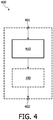
- Fig. 4 schematically shows an exemplary embodiment of the image acquisition apparatus 400 employing the system 100 of the invention, said image acquisition apparatus 400 comprising an image acquisition unit 410 connected via an internal connection with the system 100, an input connector 401, and an output connector 402.
- This arrangement advantageously increases the capabilities of the image acquisition apparatus 400, providing said image acquisition apparatus 400 with advantageous capabilities of the system 100.
- Fig. 5 schematically shows an exemplary embodiment of the workstation 500.
- the workstation comprises a system bus 501.
- a processor 510, a memory 520, a disk input/output (I/O) adapter 530, and a user interface (UI) 540 are operatively connected to the system bus 501.
- a disk storage device 531 is operatively coupled to the disk I/O adapter 530.
- a keyboard 541, a mouse 542, and a display 543 are operatively coupled to the UI 540.
- the system 100 of the invention, implemented as a computer program, is stored in the disk storage device 531.
- the workstation 500 is arranged to load the program and input data into memory 520 and execute the program on the processor 510.
- the user can input information to the workstation 500, using the keyboard 541 and/or the mouse 542.
- the workstation is arranged to output information to the display device 543 and/or to the disk 531.
- a person skilled in the art will understand that there are numerous other embodiments of the workstation 500 known in the art and that the present embodiment serves the purpose of illustrating the invention and must not be interpreted as limiting the invention to this particular embodiment.
Landscapes
- Engineering & Computer Science (AREA)
- Computer Vision & Pattern Recognition (AREA)
- Physics & Mathematics (AREA)
- General Physics & Mathematics (AREA)
- Theoretical Computer Science (AREA)
- Image Analysis (AREA)
- Measuring And Recording Apparatus For Diagnosis (AREA)
- Apparatus For Radiation Diagnosis (AREA)
Claims (9)
- System (100) zum Segmentieren eines Objekts in Bilddaten unter Verwendung von modellbasierter Bildsegmentierung, wobei das System umfasst:• eine Merkmaleinheit (120) zum Identifizieren von Merkmalen in Bilddaten, um eine externe Energie einer Masche zu berechnen, welche auf der Basis einer aktuellen Position der Masche an ein Objekt angepasst werden soll, wobei die Merkmaleinheit (120) umfasst:- eine Mögliches-Merkmal-Einheit (122) zum Auswählen einer Vielzahl von möglichen Merkmalen in den Bilddaten zum Identifizieren eines Merkmals, welches in den in den Bilddaten identifizierten Merkmalen beinhaltet sein soll;- eine Positionseinheit (124) zum Bestimmen einer Distanz von jedem möglichen Merkmal aus der Vielzahl von möglichen Merkmalen, welche sich innerhalb eines Bereichs befinden, zu der Grenze des Bereichs der Bilddaten, welche nicht von der Masche überlappt werden soll;- Mittel zum Berechnen eines Merkmalswerts von jedem von den möglichen Merkmalen;- eine Merkmalfunktionseinheit (126) zum Berechnen einer Stärke von jedem von den möglichen Merkmalen, wobei die Stärke von jedem von den möglichen Merkmalen ein Produkt eines Faktors, welcher umgekehrt proportional zu der Distanz ist, und eines Merkmalswerts des zugehörigen möglichen Merkmals ist; und- eine Evaluierungseinheit (128) zum Evaluieren jedes von den möglichen Merkmalen aus der Vielzahl von möglichen Merkmalen und zum Identifizieren des Merkmals, welches aus der Vielzahl von möglichen Merkmalen auf Basis dieser Evaluierung beinhaltet werden soll, und• eine Anpassungseinheit (140) zum Aktualisieren der Position der Masche auf Basis von zumindest der externen und internen Energie der Masche.
- System nach Anspruch 1, weiter umfassend- eine Vorpositionierungseinheit (110) zum Vorpositionieren der Masche zum Segmentieren des Objekts, dadurch Initialisieren der aktuellen Maschenposition;- eine Transformationseinheit (130) zum Berechnen einer Transformation, welche die Masche in der aktuellen Maschenposition am besten mit der vorpositionierten Masche ausrichtet;- wobei die Anpassungseinheit (140) für das Aktualisieren der aktuellen Maschenposition mittels Aktualisieren von aktuellen Positionen von Knoten der Masche konfiguriert ist, um eine gewichtete Summe von zumindest der externen Energie und der internen Energie der Masche zu minimieren; und- eine Steuerungseinheit (160) zum Evaluieren einer Konvergenzbedingung, welche zumindest von der minimierten gewichteten Summe oder von der aktualisierten aktuellen Position der Masche abhängig ist, und weiter zum Beenden des Segmentierens des Objekts, wenn die Bedingung erfüllt ist, und zum Fortsetzen des Segmentierens des Objekts, wenn die Bedingung nicht erfüllt ist.
- System nach Anspruch 1, wobei die Stärke von jedem von den möglichen Merkmalen innerhalb des Bereichs eine Funktion der Distanz von dem zugehörigen möglichen Merkmal innerhalb des Bereichs zu einer Grenze des Bereichs ist.
- System nach Anspruch 3, wobei die Bereichsgrenze mittels einer Masche definiert ist, welche an ein zweites Objekt in den Bilddaten angepasst ist.
- System nach Anspruch 3, wobei die Stärke von jedem von den möglichen Merkmalen innerhalb des Bereichs im Wesentlichen mit der Distanz von dem zugehörigen möglichen Merkmal innerhalb des Bereichs zu einer Grenze des Bereichs abnimmt.
- Nutzung des Systems (100) nach einem der Ansprüche 1 bis 5 zum Segmentieren einer Vielzahl von Objekten in Bilddaten mittels Anpassen einer Masche an jedes Objekt aus der Vielzahl von Objekten, wobei während der Anpassung einer bestimmten Masche an ein bestimmtes Objekt aus der Vielzahl von Objekten der Bereich auf Basis von aktuellen Positionen von an Objekte aus der Vielzahl von Objekten angepassten Maschen, welche sich von der bestimmten Masche unterscheiden, definiert wird.
- Bildübernahmevorrichtung (400), welche ein System (100) nach Anspruch 1 umfasst.
- Verfahren (300) zum Segmentieren eines Objekts in Bilddaten unter Verwendung von modellbasierter Bildsegmentierung, wobei das Verfahren umfasst:• einen Schritt des Identifizierens von Merkmalen in Bilddaten, um eine externe Energie einer Masche zu berechnen, welche auf der Basis einer aktuellen Position der Masche an ein Objekt angepasst werden soll, wobei der Merkmalschritt (320) umfasst:- einen Mögliches-Merkmal-Schritt (322) zum Auswählen einer Vielzahl von möglichen Merkmalen in den Bilddaten zum Identifizieren eines Merkmals, welches in den Merkmalen, welche in den Bilddaten identifiziert werden, beinhaltet sein soll;- einen Positionsschritt (324) zum Bestimmen einer Distanz von jedem möglichen Merkmal aus der Vielzahl der möglichen Merkmale, welche sich innerhalb eines Bereichs befinden, zu der Grenze des Bereichs der Bilddaten, welche nicht von der Masche überlappt werden soll;- einen Merkmalfunktionsschritt (326) zum Berechnen einer Stärke von jedem von den möglichen Merkmalen, wobei die Stärke von jedem von den möglichen Merkmalen ein Produkt eines Faktors, welcher umgekehrt proportional zu der Distanz ist, und eines Merkmalswerts des zugehörigen möglichen Merkmals ist; und- einen Evaluierungsschritt (328) zum Evaluieren jedes von den möglichen Merkmalen aus der Vielzahl von möglichen Merkmalen und zum Identifizieren des Merkmals, welches aus der Vielzahl von möglichen Merkmalen auf Basis dieser Evaluierung beinhaltet werden soll, und• einen Schritt des Aktualisierens der Position der Masche auf Basis von zumindest der internen und externen Energie der Masche.
- Computerprogrammprodukt, welches mittels einer Computeranordnung geladen werden soll, umfassend Anweisungen zum Segmentieren eines Objekts in Bilddaten unter Verwendung von modellbasierter Bildsegmentierung, wobei die Anweisungen weiter Anweisungen zum Identifizieren von Merkmalen in den Bilddaten umfassen, um eine externe Energie einer Masche zu berechnen , welche an ein Objekt in den Bilddaten auf der Basis einer aktuellen Position der Masche zur Nutzung in einem System (100) zum Segmentieren eines Objekts in den Bilddaten unter Verwendung von modellbasierter Bildsegmentierung angepasst werden soll, wobei die Computeranordnung eine Verarbeitungseinheit und einen Speicher umfasst, wobei das Computerprogrammprodukt, nachdem es geladen wurde, für die Verarbeitungseinheit eine Möglichkeit zum Ausführen von Schritten eines Verfahrens nach Anspruch 8 bereitstellt.
Priority Applications (1)
| Application Number | Priority Date | Filing Date | Title |
|---|---|---|---|
| EP09730313.5A EP2279489B1 (de) | 2008-04-07 | 2009-04-02 | Maschenkollisionsvermeidung |
Applications Claiming Priority (3)
| Application Number | Priority Date | Filing Date | Title |
|---|---|---|---|
| EP08154147 | 2008-04-07 | ||
| PCT/IB2009/051392 WO2009125319A2 (en) | 2008-04-07 | 2009-04-02 | Mesh collision avoidance |
| EP09730313.5A EP2279489B1 (de) | 2008-04-07 | 2009-04-02 | Maschenkollisionsvermeidung |
Publications (2)
| Publication Number | Publication Date |
|---|---|
| EP2279489A2 EP2279489A2 (de) | 2011-02-02 |
| EP2279489B1 true EP2279489B1 (de) | 2019-06-12 |
Family
ID=41162318
Family Applications (1)
| Application Number | Title | Priority Date | Filing Date |
|---|---|---|---|
| EP09730313.5A Active EP2279489B1 (de) | 2008-04-07 | 2009-04-02 | Maschenkollisionsvermeidung |
Country Status (5)
| Country | Link |
|---|---|
| US (1) | US8917933B2 (de) |
| EP (1) | EP2279489B1 (de) |
| JP (1) | JP5432241B2 (de) |
| CN (1) | CN102099833B (de) |
| WO (1) | WO2009125319A2 (de) |
Families Citing this family (4)
| Publication number | Priority date | Publication date | Assignee | Title |
|---|---|---|---|---|
| US8750596B2 (en) * | 2011-08-19 | 2014-06-10 | Cognex Corporation | System and method for identifying defects in a material |
| WO2013179188A1 (en) * | 2012-05-31 | 2013-12-05 | Koninklijke Philips N.V. | Method and system for quantitative evaluation of image segmentation |
| AU2015338943B2 (en) * | 2014-10-30 | 2019-09-12 | Dominion Energy Technologies, Inc. | System and methods for assigning slots and resolving slot conflicts in an electrical distribution grid |
| JP6401083B2 (ja) * | 2015-03-12 | 2018-10-03 | 富士フイルム株式会社 | 医用画像処理装置、方法およびプログラム |
Family Cites Families (18)
| Publication number | Priority date | Publication date | Assignee | Title |
|---|---|---|---|---|
| US5819016A (en) * | 1993-10-05 | 1998-10-06 | Kabushiki Kaisha Toshiba | Apparatus for modeling three dimensional information |
| WO2002073536A2 (en) * | 2001-03-09 | 2002-09-19 | Koninklijke Philips Electronics N.V. | Image segmentation |
| GB2377604B (en) * | 2001-07-09 | 2005-09-28 | Superscape Plc | Mesh compression |
| JP3822515B2 (ja) * | 2002-03-29 | 2006-09-20 | 株式会社東芝 | 障害物検知装置及びその方法 |
| JP4575157B2 (ja) * | 2002-07-19 | 2010-11-04 | コーニンクレッカ フィリップス エレクトロニクス エヌ ヴィ | メッシュ適応による多数の対象又は複合的な対象の同時セグメンテーション |
| AU2003278538A1 (en) * | 2002-11-20 | 2004-06-15 | Koninklijke Philips Electronics N.V. | Image processing system for automatic adaptation of a 3-d mesh model onto a 3-d surface of an object |
| EP1437685A3 (de) * | 2003-01-13 | 2004-07-21 | Philips Intellectual Property & Standards GmbH | Verfahren zum Segmentieren einer dreidimensionalen Struktur |
| ATE476720T1 (de) * | 2003-06-13 | 2010-08-15 | Koninkl Philips Electronics Nv | Dreidimensionale bildsegmentierung |
| JP3962718B2 (ja) * | 2003-12-01 | 2007-08-22 | キヤノン株式会社 | 情報処理装置及びその制御方法、プログラム |
| US7292250B2 (en) * | 2004-03-31 | 2007-11-06 | Dreamworks Animation, Llc | Character deformation pipeline for computer-generated animation |
| CN1331099C (zh) * | 2004-04-23 | 2007-08-08 | 中国科学院自动化研究所 | 基于内容的图像识别方法 |
| EP1603076A1 (de) * | 2004-05-13 | 2005-12-07 | Aalborg Universitet | Rechnergestützte Hirnrindengrenzextraktion aus MR-Bildern |
| CN101116104B (zh) * | 2005-02-10 | 2012-07-04 | 皇家飞利浦电子股份有限公司 | 用于分割多维数据集中的表面的方法、系统 |
| US7957572B2 (en) * | 2005-02-11 | 2011-06-07 | Koninklijke Philips Electronics N.V. | Image processing device and method |
| US8571278B2 (en) * | 2005-06-24 | 2013-10-29 | The University Of Iowa Research Foundation | System and methods for multi-object multi-surface segmentation |
| US8358819B2 (en) * | 2005-06-24 | 2013-01-22 | University Of Iowa Research Foundation | System and methods for image segmentation in N-dimensional space |
| US8929621B2 (en) * | 2005-12-20 | 2015-01-06 | Elekta, Ltd. | Methods and systems for segmentation and surface matching |
| US7907768B2 (en) * | 2006-12-19 | 2011-03-15 | Fujifilm Corporation | Method and apparatus for probabilistic atlas based on shape modeling technique |
-
2009
- 2009-04-02 JP JP2011502487A patent/JP5432241B2/ja active Active
- 2009-04-02 EP EP09730313.5A patent/EP2279489B1/de active Active
- 2009-04-02 US US12/936,425 patent/US8917933B2/en active Active
- 2009-04-02 CN CN200980111582.8A patent/CN102099833B/zh active Active
- 2009-04-02 WO PCT/IB2009/051392 patent/WO2009125319A2/en not_active Ceased
Non-Patent Citations (1)
| Title |
|---|
| None * |
Also Published As
| Publication number | Publication date |
|---|---|
| US8917933B2 (en) | 2014-12-23 |
| JP2011516957A (ja) | 2011-05-26 |
| CN102099833B (zh) | 2016-08-10 |
| WO2009125319A3 (en) | 2010-01-07 |
| JP5432241B2 (ja) | 2014-03-05 |
| EP2279489A2 (de) | 2011-02-02 |
| US20110033104A1 (en) | 2011-02-10 |
| CN102099833A (zh) | 2011-06-15 |
| WO2009125319A2 (en) | 2009-10-15 |
Similar Documents
| Publication | Publication Date | Title |
|---|---|---|
| US10210613B2 (en) | Multiple landmark detection in medical images based on hierarchical feature learning and end-to-end training | |
| EP2074585B1 (de) | Modellbasierte ortung der koronaren zentrallinie | |
| US8135189B2 (en) | System and method for organ segmentation using surface patch classification in 2D and 3D images | |
| EP2186058B1 (de) | Anatomisch eingeschränkte bilderfassung | |
| JP4575157B2 (ja) | メッシュ適応による多数の対象又は複合的な対象の同時セグメンテーション | |
| Acton et al. | Biomedical image analysis: Segmentation | |
| US20180365876A1 (en) | Method, apparatus and system for spine labeling | |
| US12373953B2 (en) | Segmentating a tubular feature | |
| US7460699B2 (en) | System and method for a semi-automatic quantification of delayed enchancement images | |
| EP2279489B1 (de) | Maschenkollisionsvermeidung | |
| US12412280B2 (en) | Medical image segmentation and atlas image selection | |
| US8260586B2 (en) | Method of and a system for adapting a geometric model using multiple partial transformations | |
| US8582883B2 (en) | Simultaneous model-based segmentation of objects satisfying pre-defined spatial relationships | |
| US9754411B2 (en) | Path proximity rendering | |
| EP4012650A1 (de) | Segmentierung einer anatomischen struktur in einem bild | |
| EP2143072B1 (de) | Progressive modellbasierte adaption | |
| Barba-J et al. | A local multiscale variational approach for left ventricle analysis in cardiac images | |
| WO2009034499A2 (en) | Flexible 'plug-and-play' medical image segmentation |
Legal Events
| Date | Code | Title | Description |
|---|---|---|---|
| PUAI | Public reference made under article 153(3) epc to a published international application that has entered the european phase |
Free format text: ORIGINAL CODE: 0009012 |
|
| 17P | Request for examination filed |
Effective date: 20101108 |
|
| AK | Designated contracting states |
Kind code of ref document: A2 Designated state(s): AT BE BG CH CY CZ DE DK EE ES FI FR GB GR HR HU IE IS IT LI LT LU LV MC MK MT NL NO PL PT RO SE SI SK TR |
|
| AX | Request for extension of the european patent |
Extension state: AL BA RS |
|
| DAX | Request for extension of the european patent (deleted) | ||
| RAP1 | Party data changed (applicant data changed or rights of an application transferred) |
Owner name: KONINKLIJKE PHILIPS N.V. Owner name: PHILIPS INTELLECTUAL PROPERTY & STANDARDS GMBH |
|
| 17Q | First examination report despatched |
Effective date: 20150320 |
|
| GRAP | Despatch of communication of intention to grant a patent |
Free format text: ORIGINAL CODE: EPIDOSNIGR1 |
|
| STAA | Information on the status of an ep patent application or granted ep patent |
Free format text: STATUS: GRANT OF PATENT IS INTENDED |
|
| INTG | Intention to grant announced |
Effective date: 20190123 |
|
| RIN1 | Information on inventor provided before grant (corrected) |
Inventor name: WOLZ, ROBIN M. B. Inventor name: FRANZ, ASTRID R. Inventor name: KLINDER, TOBIAS Inventor name: LORENZ, CRISTIAN |
|
| GRAS | Grant fee paid |
Free format text: ORIGINAL CODE: EPIDOSNIGR3 |
|
| GRAA | (expected) grant |
Free format text: ORIGINAL CODE: 0009210 |
|
| STAA | Information on the status of an ep patent application or granted ep patent |
Free format text: STATUS: THE PATENT HAS BEEN GRANTED |
|
| AK | Designated contracting states |
Kind code of ref document: B1 Designated state(s): AT BE BG CH CY CZ DE DK EE ES FI FR GB GR HR HU IE IS IT LI LT LU LV MC MK MT NL NO PL PT RO SE SI SK TR |
|
| REG | Reference to a national code |
Ref country code: GB Ref legal event code: FG4D |
|
| REG | Reference to a national code |
Ref country code: CH Ref legal event code: EP |
|
| REG | Reference to a national code |
Ref country code: AT Ref legal event code: REF Ref document number: 1143557 Country of ref document: AT Kind code of ref document: T Effective date: 20190615 |
|
| REG | Reference to a national code |
Ref country code: DE Ref legal event code: R096 Ref document number: 602009058706 Country of ref document: DE |
|
| REG | Reference to a national code |
Ref country code: IE Ref legal event code: FG4D |
|
| REG | Reference to a national code |
Ref country code: DE Ref legal event code: R084 Ref document number: 602009058706 Country of ref document: DE |
|
| REG | Reference to a national code |
Ref country code: NL Ref legal event code: MP Effective date: 20190612 |
|
| REG | Reference to a national code |
Ref country code: LT Ref legal event code: MG4D |
|
| PG25 | Lapsed in a contracting state [announced via postgrant information from national office to epo] |
Ref country code: HR Free format text: LAPSE BECAUSE OF FAILURE TO SUBMIT A TRANSLATION OF THE DESCRIPTION OR TO PAY THE FEE WITHIN THE PRESCRIBED TIME-LIMIT Effective date: 20190612 Ref country code: SE Free format text: LAPSE BECAUSE OF FAILURE TO SUBMIT A TRANSLATION OF THE DESCRIPTION OR TO PAY THE FEE WITHIN THE PRESCRIBED TIME-LIMIT Effective date: 20190612 Ref country code: LT Free format text: LAPSE BECAUSE OF FAILURE TO SUBMIT A TRANSLATION OF THE DESCRIPTION OR TO PAY THE FEE WITHIN THE PRESCRIBED TIME-LIMIT Effective date: 20190612 Ref country code: ES Free format text: LAPSE BECAUSE OF FAILURE TO SUBMIT A TRANSLATION OF THE DESCRIPTION OR TO PAY THE FEE WITHIN THE PRESCRIBED TIME-LIMIT Effective date: 20190612 Ref country code: NO Free format text: LAPSE BECAUSE OF FAILURE TO SUBMIT A TRANSLATION OF THE DESCRIPTION OR TO PAY THE FEE WITHIN THE PRESCRIBED TIME-LIMIT Effective date: 20190912 Ref country code: FI Free format text: LAPSE BECAUSE OF FAILURE TO SUBMIT A TRANSLATION OF THE DESCRIPTION OR TO PAY THE FEE WITHIN THE PRESCRIBED TIME-LIMIT Effective date: 20190612 |
|
| PG25 | Lapsed in a contracting state [announced via postgrant information from national office to epo] |
Ref country code: GR Free format text: LAPSE BECAUSE OF FAILURE TO SUBMIT A TRANSLATION OF THE DESCRIPTION OR TO PAY THE FEE WITHIN THE PRESCRIBED TIME-LIMIT Effective date: 20190913 Ref country code: BG Free format text: LAPSE BECAUSE OF FAILURE TO SUBMIT A TRANSLATION OF THE DESCRIPTION OR TO PAY THE FEE WITHIN THE PRESCRIBED TIME-LIMIT Effective date: 20190912 Ref country code: LV Free format text: LAPSE BECAUSE OF FAILURE TO SUBMIT A TRANSLATION OF THE DESCRIPTION OR TO PAY THE FEE WITHIN THE PRESCRIBED TIME-LIMIT Effective date: 20190612 |
|
| REG | Reference to a national code |
Ref country code: AT Ref legal event code: MK05 Ref document number: 1143557 Country of ref document: AT Kind code of ref document: T Effective date: 20190612 |
|
| PG25 | Lapsed in a contracting state [announced via postgrant information from national office to epo] |
Ref country code: NL Free format text: LAPSE BECAUSE OF FAILURE TO SUBMIT A TRANSLATION OF THE DESCRIPTION OR TO PAY THE FEE WITHIN THE PRESCRIBED TIME-LIMIT Effective date: 20190612 Ref country code: PT Free format text: LAPSE BECAUSE OF FAILURE TO SUBMIT A TRANSLATION OF THE DESCRIPTION OR TO PAY THE FEE WITHIN THE PRESCRIBED TIME-LIMIT Effective date: 20191014 Ref country code: SK Free format text: LAPSE BECAUSE OF FAILURE TO SUBMIT A TRANSLATION OF THE DESCRIPTION OR TO PAY THE FEE WITHIN THE PRESCRIBED TIME-LIMIT Effective date: 20190612 Ref country code: CZ Free format text: LAPSE BECAUSE OF FAILURE TO SUBMIT A TRANSLATION OF THE DESCRIPTION OR TO PAY THE FEE WITHIN THE PRESCRIBED TIME-LIMIT Effective date: 20190612 Ref country code: RO Free format text: LAPSE BECAUSE OF FAILURE TO SUBMIT A TRANSLATION OF THE DESCRIPTION OR TO PAY THE FEE WITHIN THE PRESCRIBED TIME-LIMIT Effective date: 20190612 Ref country code: EE Free format text: LAPSE BECAUSE OF FAILURE TO SUBMIT A TRANSLATION OF THE DESCRIPTION OR TO PAY THE FEE WITHIN THE PRESCRIBED TIME-LIMIT Effective date: 20190612 Ref country code: AT Free format text: LAPSE BECAUSE OF FAILURE TO SUBMIT A TRANSLATION OF THE DESCRIPTION OR TO PAY THE FEE WITHIN THE PRESCRIBED TIME-LIMIT Effective date: 20190612 |
|
| PG25 | Lapsed in a contracting state [announced via postgrant information from national office to epo] |
Ref country code: IS Free format text: LAPSE BECAUSE OF FAILURE TO SUBMIT A TRANSLATION OF THE DESCRIPTION OR TO PAY THE FEE WITHIN THE PRESCRIBED TIME-LIMIT Effective date: 20191012 Ref country code: IT Free format text: LAPSE BECAUSE OF FAILURE TO SUBMIT A TRANSLATION OF THE DESCRIPTION OR TO PAY THE FEE WITHIN THE PRESCRIBED TIME-LIMIT Effective date: 20190612 |
|
| REG | Reference to a national code |
Ref country code: DE Ref legal event code: R097 Ref document number: 602009058706 Country of ref document: DE |
|
| RAP2 | Party data changed (patent owner data changed or rights of a patent transferred) |
Owner name: KONINKLIJKE PHILIPS N.V. Owner name: PHILIPS INTELLECTUAL PROPERTY & STANDARDS GMBH |
|
| PG25 | Lapsed in a contracting state [announced via postgrant information from national office to epo] |
Ref country code: TR Free format text: LAPSE BECAUSE OF FAILURE TO SUBMIT A TRANSLATION OF THE DESCRIPTION OR TO PAY THE FEE WITHIN THE PRESCRIBED TIME-LIMIT Effective date: 20190612 |
|
| PLBE | No opposition filed within time limit |
Free format text: ORIGINAL CODE: 0009261 |
|
| STAA | Information on the status of an ep patent application or granted ep patent |
Free format text: STATUS: NO OPPOSITION FILED WITHIN TIME LIMIT |
|
| PG25 | Lapsed in a contracting state [announced via postgrant information from national office to epo] |
Ref country code: DK Free format text: LAPSE BECAUSE OF FAILURE TO SUBMIT A TRANSLATION OF THE DESCRIPTION OR TO PAY THE FEE WITHIN THE PRESCRIBED TIME-LIMIT Effective date: 20190612 Ref country code: PL Free format text: LAPSE BECAUSE OF FAILURE TO SUBMIT A TRANSLATION OF THE DESCRIPTION OR TO PAY THE FEE WITHIN THE PRESCRIBED TIME-LIMIT Effective date: 20190612 |
|
| 26N | No opposition filed |
Effective date: 20200313 |
|
| PG25 | Lapsed in a contracting state [announced via postgrant information from national office to epo] |
Ref country code: IS Free format text: LAPSE BECAUSE OF FAILURE TO SUBMIT A TRANSLATION OF THE DESCRIPTION OR TO PAY THE FEE WITHIN THE PRESCRIBED TIME-LIMIT Effective date: 20200224 Ref country code: SI Free format text: LAPSE BECAUSE OF FAILURE TO SUBMIT A TRANSLATION OF THE DESCRIPTION OR TO PAY THE FEE WITHIN THE PRESCRIBED TIME-LIMIT Effective date: 20190612 |
|
| PG2D | Information on lapse in contracting state deleted |
Ref country code: IS |
|
| PG25 | Lapsed in a contracting state [announced via postgrant information from national office to epo] |
Ref country code: IS Free format text: LAPSE BECAUSE OF FAILURE TO SUBMIT A TRANSLATION OF THE DESCRIPTION OR TO PAY THE FEE WITHIN THE PRESCRIBED TIME-LIMIT Effective date: 20191112 |
|
| PG25 | Lapsed in a contracting state [announced via postgrant information from national office to epo] |
Ref country code: MC Free format text: LAPSE BECAUSE OF FAILURE TO SUBMIT A TRANSLATION OF THE DESCRIPTION OR TO PAY THE FEE WITHIN THE PRESCRIBED TIME-LIMIT Effective date: 20190612 |
|
| REG | Reference to a national code |
Ref country code: CH Ref legal event code: PL |
|
| REG | Reference to a national code |
Ref country code: DE Ref legal event code: R081 Ref document number: 602009058706 Country of ref document: DE Owner name: PHILIPS GMBH, DE Free format text: FORMER OWNER: PHILIPS INTELLECTUAL PROPERTY & STANDARDS GMBH, 20099 HAMBURG, DE |
|
| PG25 | Lapsed in a contracting state [announced via postgrant information from national office to epo] |
Ref country code: CH Free format text: LAPSE BECAUSE OF NON-PAYMENT OF DUE FEES Effective date: 20200430 Ref country code: LU Free format text: LAPSE BECAUSE OF NON-PAYMENT OF DUE FEES Effective date: 20200402 Ref country code: LI Free format text: LAPSE BECAUSE OF NON-PAYMENT OF DUE FEES Effective date: 20200430 |
|
| REG | Reference to a national code |
Ref country code: BE Ref legal event code: MM Effective date: 20200430 |
|
| PG25 | Lapsed in a contracting state [announced via postgrant information from national office to epo] |
Ref country code: BE Free format text: LAPSE BECAUSE OF NON-PAYMENT OF DUE FEES Effective date: 20200430 |
|
| PG25 | Lapsed in a contracting state [announced via postgrant information from national office to epo] |
Ref country code: IE Free format text: LAPSE BECAUSE OF NON-PAYMENT OF DUE FEES Effective date: 20200402 |
|
| PG25 | Lapsed in a contracting state [announced via postgrant information from national office to epo] |
Ref country code: MT Free format text: LAPSE BECAUSE OF FAILURE TO SUBMIT A TRANSLATION OF THE DESCRIPTION OR TO PAY THE FEE WITHIN THE PRESCRIBED TIME-LIMIT Effective date: 20190612 Ref country code: CY Free format text: LAPSE BECAUSE OF FAILURE TO SUBMIT A TRANSLATION OF THE DESCRIPTION OR TO PAY THE FEE WITHIN THE PRESCRIBED TIME-LIMIT Effective date: 20190612 |
|
| PG25 | Lapsed in a contracting state [announced via postgrant information from national office to epo] |
Ref country code: MK Free format text: LAPSE BECAUSE OF FAILURE TO SUBMIT A TRANSLATION OF THE DESCRIPTION OR TO PAY THE FEE WITHIN THE PRESCRIBED TIME-LIMIT Effective date: 20190612 |
|
| PGFP | Annual fee paid to national office [announced via postgrant information from national office to epo] |
Ref country code: FR Payment date: 20240430 Year of fee payment: 16 |
|
| PGFP | Annual fee paid to national office [announced via postgrant information from national office to epo] |
Ref country code: DE Payment date: 20250428 Year of fee payment: 17 |
|
| PG25 | Lapsed in a contracting state [announced via postgrant information from national office to epo] |
Ref country code: FR Free format text: LAPSE BECAUSE OF NON-PAYMENT OF DUE FEES Effective date: 20250430 |
|
| REG | Reference to a national code |
Ref country code: GB Ref legal event code: 746 Effective date: 20190809 |
|
| PGFP | Annual fee paid to national office [announced via postgrant information from national office to epo] |
Ref country code: GB Payment date: 20260309 Year of fee payment: 18 |