EP2279497B1 - Navigation tridimensionnelle - Google Patents
Navigation tridimensionnelle Download PDFInfo
- Publication number
- EP2279497B1 EP2279497B1 EP09731588.1A EP09731588A EP2279497B1 EP 2279497 B1 EP2279497 B1 EP 2279497B1 EP 09731588 A EP09731588 A EP 09731588A EP 2279497 B1 EP2279497 B1 EP 2279497B1
- Authority
- EP
- European Patent Office
- Prior art keywords
- virtual camera
- earth
- target
- tilt
- location
- Prior art date
- Legal status (The legal status is an assumption and is not a legal conclusion. Google has not performed a legal analysis and makes no representation as to the accuracy of the status listed.)
- Not-in-force
Links
Images


Classifications
-
- G—PHYSICS
- G06—COMPUTING OR CALCULATING; COUNTING
- G06T—IMAGE DATA PROCESSING OR GENERATION, IN GENERAL
- G06T15/00—Three-dimensional [3D] image rendering
- G06T15/10—Geometric effects
- G06T15/20—Perspective computation
-
- G—PHYSICS
- G06—COMPUTING OR CALCULATING; COUNTING
- G06T—IMAGE DATA PROCESSING OR GENERATION, IN GENERAL
- G06T15/00—Three-dimensional [3D] image rendering
- G06T15/10—Geometric effects
- G06T15/40—Hidden part removal
-
- G—PHYSICS
- G06—COMPUTING OR CALCULATING; COUNTING
- G06T—IMAGE DATA PROCESSING OR GENERATION, IN GENERAL
- G06T15/00—Three-dimensional [3D] image rendering
- G06T15/50—Lighting effects
-
- G—PHYSICS
- G06—COMPUTING OR CALCULATING; COUNTING
- G06T—IMAGE DATA PROCESSING OR GENERATION, IN GENERAL
- G06T17/00—Three-dimensional [3D] modelling for computer graphics
- G06T17/05—Geographic models
-
- G—PHYSICS
- G06—COMPUTING OR CALCULATING; COUNTING
- G06T—IMAGE DATA PROCESSING OR GENERATION, IN GENERAL
- G06T19/00—Manipulating three-dimensional [3D] models or images for computer graphics
- G06T19/003—Navigation within 3D models or images
Definitions
- This invention relates to navigating in a three dimensional environment.
- the three dimensional environment includes a virtual camera that defines what three dimensional data to display.
- the virtual camera has a perspective according to its position and orientation. By changing the perspective of the virtual camera, a user can navigate through the three dimensional environment.
- EP0471484 (Xerox Corporation) describes techniques for operating a system to produce the perception of a moving viewpoint within a three-dimensional work-space.
- the viewpoint can approach the point of interest asymptotically, with both radial and lateral motion.
- the orientation of the viewpoint can rotate to keep the point of interest in the field of view.
- the field of view can also be centered about the point of interest by rotating the viewpoint.
- a geographic information system is one type of system that uses a virtual camera to navigate through a three dimensional environment.
- a geographic information system is a system for storing, retrieving, manipulating, and displaying a substantially spherical three dimensional model of the Earth.
- the three dimensional model may include satellite images texture mapped to terrain, such as mountains, valleys, and canyons. Further, the three dimensional model may include buildings and other three dimensional features.
- the virtual camera in the geographic information system may view the spherical three dimensional model of the Earth from different perspectives.
- An aerial perspective of the model of the Earth may show satellite images, but the terrain and buildings be hard to see.
- a ground-level perspective of the model may show the terrain and buildings in detail. In current systems, navigating from an aerial perspective to a ground-level perspective may be difficult and disorienting to a user.
- Methods and systems are needed for navigating from an aerial perspective to a ground-level perspective that are less disorienting to a user.
- a method as set out in claim 1 there is provided a method as set out in claim 1.
- a computer readable medium as set out in claim 9.
- embodiments of this invention navigate a virtual camera from an aerial perspective to a ground-level perspective in a manner that is less disorienting to a user.
- Embodiments of this invention relate to navigating a virtual camera in a three dimensional environment along a swoop trajectory.
- references to "one embodiment”, “an embodiment”, “an example embodiment”, etc. indicate that the embodiment described may include a particular feature, structure, or characteristic, but every embodiment may not necessarily include the particular feature, structure, or characteristic. Moreover, such phrases are not necessarily referring to the same embodiment. Further, when a particular feature, structure, or characteristic is described in connection with an embodiment, it is submitted that it is within the knowledge of one skilled in the art to effect such feature, structure, or characteristic in connection with other embodiments whether or not explicitly described.
- swoop navigation moves the camera to achieve a desired position and orientation with respect to a target.
- Swoop parameters encode position and orientation of the camera with respect to the target.
- the swoop parameters may include: (1) a distance to the target, (2) a tilt with respect to the vertical at the target, (3) an azimuth and, optionally, (4) a roll.
- an azimuth may be the cardinal direction of the camera.
- Swoop navigation may be analogous to a camera-on-a-stick.
- a virtual camera is connected to a target point by a stick.
- a vector points upward from the target point.
- the upward vector may, for example, be normal to a surface of a three dimensional model.
- the vector may extend from a center of the three dimensional model through the target.
- the stick can also rotate around the vector by changing the azimuth of the camera relative to the target point.
- FIG. 1A shows a diagram 100 illustrating a simple swoop trajectory useful for understanding the present invention.
- Diagram 100 shows a virtual camera at a location 102.
- the virtual camera has an aerial perspective.
- the user wishes to navigate from the aerial perspective to a ground-level perspective of a building 108.
- the virtual camera is oriented straight down, therefore its tilt is zero, and the virtual camera is a distance 116 from a target 110.
- distance 116 is reduced to determine a new distance 118.
- the distance between the virtual camera and the target is reduced.
- a tilt 112 is also determined. Tilt 112 is an angle between a vector directed upwards from target 110 and a line segment connecting location 104 and target 110. Tilt 112 may be determined according to reduced distance 118.
- the camera's next position on the swoop trajectory corresponds to tilt 112 and reduced distance 118.
- the camera is repositioned to a location 104.
- Location 104 is distance 118 away from target 112.
- the camera is rotated by tilt 112 to face target 110.
- the process is repeated until the virtual camera reaches target 110.
- the tilt is 90 degrees, and the virtual camera faces building 108. In this way, it is possible to easily navigates from an aerial perspective at location 102 to a ground perspective of building 108. More detail on the operation of swoop navigation, its alternatives and other embodiments are described below.
- the swoop trajectory in diagram 100 may also be described in terms of the swoop parameters and the stick analogy mentioned above.
- the tilt value increases to 90 degrees, the distance value decreases to zero, and the azimuth value remains constant.
- a vector points upward from target 110.
- the length of the stick decreases and the stick angles away from the vector.
- the swoop parameters may be updated in other ways to form other trajectories.
- FIG. 1B shows a diagram 140 illustrating another trajectory useful for understanding the present invention.
- the trajectory in diagram 140 shows the virtual camera helicoptering around target 110.
- Diagram 140 shows a virtual camera starting at a position 148. Traveling along the trajectory, the virtual camera stays equidistant from the target. In terms of swoop parameters, distance stays constant, but the tilt and azimuth values may change as the camera moves along the trajectory. In terms of the stick analogy, the length of the stick stays constant, but the stick pivots around the target. In this way, the camera moves along the surface of a sphere with an origin at the target.
- the trajectory shown in diagram 140 may be used, for example, to view a target point from different perspectives. However, the trajectory in diagram 140 does not necessarily transition a user from an aerial to a ground-level perspective.
- FIG. 1B shows that target 110 need not project out of the center of the virtual camera. This will be described in more detail with respect to FIGS. 4 and 5 .
- FIG. 1C shows a diagram 170 illustrating a swoop trajectory that both shows a target from different perspectives and transitions from an aerial to a ground-level perspective.
- a virtual camera starts the swoop trajectory in diagram 170 at a location 174.
- the virtual camera moves from location 174 to a location 176, the virtual camera approaches the target and tilts relative to the target as with the swoop trajectory in diagram 100. But, the virtual camera also helicopters around the target as with the trajectory in diagram 140.
- the swoop trajectory shown in diagram 170 continues until the virtual camera reaches target 110.
- the tilt value increases to 90 degrees
- the distance value decreases to zero
- the length of the stick decreases, and the stick both tilts away and rotates around a vector directed upwards from target 110.
- FIG. 1D shows a diagram 180 illustrating how a swoop trajectory may be used to navigate through a three dimensional space.
- the three dimensional space includes two buildings 182 and 184.
- a virtual camera sits at a location 186.
- Target 110 is on top of building 184.
- Target 110 may be selected in response to a user input as is described below with respect to FIGS. 4 and 5 .
- the virtual camera moves from location 186 at building 182 along a swoop trajectory 188 to target 110 at building 184.
- the virtual camera swoops from building 182 to building 184.
- a swoop trajectory may be used to navigate through a three dimensional space.
- the target location may be in motion.
- swoop navigation may be used to follow the moving target. An example of calculating a swoop trajectory with a moving target is described in detail below.
- FIG. 2 is a screenshot of a user interface 200 of a geographic information system.
- User interface 200 includes a display area 202 for displaying geographic information/data.
- the data displayed in display area 202 is from the perspective of a virtual camera.
- the perspective is defined by a frustum such as, for example, a three dimensional pyramid with the top spliced off. Geographic data within the frustum can be displayed at varying levels of detail depending on its distance from the virtual camera.
- Example geographic data displayed in display area 202 include images of the Earth. These images can be rendered onto a geometry representing the Earth's terrain creating a three dimensional model of the Earth. Other data that may be displayed include three dimensional models of buildings.
- User interface 200 includes controls 204 for changing the virtual camera's orientation.
- Controls 204 enable a user to change, for example, the virtual camera's altitude, latitude, longitude, pitch, yaw and roll.
- controls 204 are manipulated using a computer pointing device such as a mouse.
- a computer pointing device such as a mouse.
- the virtual camera's orientation changes, the virtual camera's frustum and the geographic information/data displayed also change.
- a user can also control the virtual camera's orientation using other computer input devices such as, for example, a computer keyboard or a joystick.
- the virtual camera has an aerial perspective of the Earth.
- the user may select a target by selecting a position on display area 200. Then, the camera may swoop down to a ground perspective of the target using the swoop trajectory described with respect to FIG. 1 .
- the geographic information system can be operated using a client-server computer architecture.
- user interface 200 resides on a client machine.
- the client machine can be a general-purpose computer with a processor, local memory, display, and one or more computer input devices such as a keyboard, a mouse and/or a joystick.
- the client machine can be a specialized computing device such as, for example, a mobile handset.
- the client machine communicates with one or more servers over one or more networks, such as the Internet. Similar to the client machine, the server can be implemented using any general-purpose computer capable of serving data to the client.
- the architecture of the geographic information system client is described in more detail with respect to FIG. 12 .
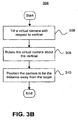
- FIG. 3 is a flowchart illustrating a method 300 for swoop navigation according to an embodiment of the present invention.
- Method 300 begins by determining a target at a step 302. The target may be determined according to a user selection on display area 202 in FIG. 2 . How the target is determined is discussed in more detail with respect to FIGS. 4 and 5 .
- new swoop parameters may be determined and a virtual camera is repositioned.
- the new swoop parameters may include a tilt, an azimuth, and a distance between the virtual camera and the target.
- the distance between the virtual camera and the target may be reduced logarithmically.
- the tilt angle may be determined according to the reduced distance.
- the virtual camera may be repositioned by translating to the target, angling the virtual camera is by the tilt, and translating away from the target by the new distance.
- Step 304 is described in more detail with respect to FIG. 3B . Further, one possible way to calculate swoop parameters is discussed in detail with respect to FIGS. 7A-C and FIGS. 8A-B .
- the curvature of the Earth may introduce roll. Roll may be disorienting to a user.
- the virtual camera is rotated to compensate for the curvature of the Earth at step 306. Rotating the camera to reduce roll is discussed in more detail with respect to FIG. 9 .
- the target may appear in a different location on a display area 202 in FIG. 2 .
- Changing the position of the target on display area 202 may be disorienting to a user.
- the target's projection onto the display area is restored by rotating the model of the Earth. Restoring display area projection is discussed in more detail with respect to FIG. 10 .
- the GIS client may receive more detailed information about terrain or buildings.
- the swoop trajectory may collide with the terrain or buildings.
- steps 304 through 310 are repeated until the virtual camera is close to the target at decision block 312.
- the process is repeated until the distance between the virtual camera and the target is below a threshold. In this way, the virtual camera captures a close-up view of the target without being too close as to distort the target.
- method 300 may also navigate a virtual camera towards a moving target. If the distance is reduced in step 302 according to the speed of the target, method 300 may be cause the virtual camera to follow the target at a specified distance.
- FIG. 3B shows step 304 of method 300 in FIG. 3A in more detail.
- step 304 includes updating swoop parameters and repositioning the virtual camera according to the swoop parameters.
- the swoop parameters may include a tilt, an azimuth and a distance between the virtual camera and the target.
- the virtual camera is tilted. In other words, an angle between the line segment connecting the target and the virtual camera and a vector directed upwards from the target is increased.
- an azimuth of a virtual camera is changed. According to the azimuth, the camera is rotated around the vector directed upwards from the target. Finally, the camera is positioned such that it is at a new distance away from the target.
- One way to calculate new tilt, azimuth and distance values is discussed with respect to FIGS. 7A-C and FIGS. 8A-B .
- FIGS. 4-6 , 7A-C , 8A-B , 9-10 , and 11A-B elaborate on the method 300 in FIGS. 3A-B . They provide various alternative embodiments of the method 300. However, they are not meant to limit method 300.
- FIGS. 4 and 5 show diagrams illustrating a method for determining a target, which may be used in step 302 of FIG. 3 .
- FIG. 4 shows a diagram 400.
- Diagram 400 shows a model of the Earth 402.
- Diagram 400 also shows a focal point 406 of a virtual camera.
- the virtual camera is used to capture and to display information as described with respect to FIG. 2 .
- the virtual camera has a focal length 408 and a viewport 410.
- Viewport 410 corresponds to display area 202 in FIG. 2 .
- a user selects a position on display area 202, and the position corresponds to a point 412 on viewport 410.
- the target is determined by extending a ray from the virtual camera to determine an intersection with the model.
- a ray 414 extends from a focal point 406 through point 412. Ray 414 intersects with model 402 at a location 404.
- the target is the portion of model 402 at location 404.
- a ray may be extended from a focal point 406 through the center of viewport 410.
- FIG. 5 illustrates adjusting the target location determined in FIG. 4 , according to an optional feature.
- FIG. 5 shows a diagram 500.
- Diagram 500 shows a virtual camera at a location 506 and a building 502 in a three-dimensional model. A ray extends from location 506 to building 502 to determine an intersection 510.
- the target location of the camera may not be building 502 itself.
- the target location may be a location offset from building 502 that provides a view of building 502. So, the target is set to a location 508.
- the virtual camera swoops from location 506 along a trajectory 504 to location 508. In this way, the virtual camera transitions from a vertical, aerial perspective to a horizontal, ground perspective of building 502.
- FIG. 6 shows a diagram 602 illustrating swoop navigation with an initial, non-zero tilt.
- Diagram 602 shows a virtual camera at a location 602 with an initial tilt.
- the virtual camera swoops along a trajectory 606 from location 602 to a target location 604.
- FIG. 7A is a flowchart illustrating a method 700 for determining the tilt and the reduced distance.
- Method 700 begins by determining a reduced distance logarithmically at step 702.
- a logarithmic function is useful because it moves the virtual camera through the high aerial portion of the swoop trajectory quickly.
- a logarithmic function moves the virtual camera more slowly as it approaches the ground.
- the distance may be converted to a logarithmic level.
- the logarithmic level may be increased by a change parameter. Then, the logarithmic level is converted back into a distance using an exponential function.
- ⁇ is the change parameter
- L is the logarithmic level
- C is the current distance
- R is the reduced distance
- a tilt is determined according to the distance.
- Method 700 illustrates two alternative steps for determining the tilt.
- the tilt is determined by applying an absolute tilt function.
- the tilt is determined by applying an incremental tilt function.
- FIG. 7B illustrates the absolute tilt function of step 710 in more detail.
- the absolute tilt function defines a tilt for each distance. This has the effect of creating a predefined swoop trajectory.
- three distance values are converted to logarithmic levels.
- the three distance values converted to logarithmic levels are: (1) the reduced distance to the target calculated in step 702, (2) the distance to the target at the start of the swoop trajectory, and (3) a threshold distance ending the swoop trajectory as described for step 312 in FIG. 3 .
- S is the starting distance
- T is the threshold distance
- R is the reduced distance
- L S is the starting logarithmic level
- L T is the threshold logarithmic level
- L R is the logarithmic level of the reduced distance
- a tilt value is interpolated based on the logarithmic levels (L S , L T , L R ), a starting tilt value and an ending tilt value.
- L S , L T , L R logarithmic levels
- the ending tilt value will generally be 90 degrees, which may be parallel to the ground.
- the interpolation function may be a linear, quadratic, exponential, logarithmic, or other function as is apparent to those of skill in the art.
- ⁇ L R - L S L T - L S • ⁇ E - ⁇ S + ⁇ S , where ⁇ is the new tilt, ⁇ E is the ending tilt value, ⁇ S is the starting tilt value, and the other variables are defined as described above.
- the absolute tilt function results in a pre-defined swoop trajectory.
- the swoop trajectory may need to be adjusted due to streaming terrain or a moving target. If the swoop trajectory needs to be adjusted, an incremental tilt function as in step 720 may be preferred.
- FIG. 7C depicts the incremental tilt function in step 720 in greater detail.
- the incremental tilt function calculates a change in tilt and increments the current tilt according to the change.
- the absolute tilt function as described for FIG. 7B , is applied to the current distance.
- the absolute tilt function returns a first tilt value.
- the absolute tilt function is applied again. In this step, the absolute tilt function is applied to the reduced distance calculated in step 702. As result, the absolute tilt function returns a second tilt value.
- the current tilt value is adjusted according to the first tilt value determined in step 722 and the second tilt value determined in step 724.
- the current tilt value is incremented by the difference between the second tilt and the first tilt to determine the new tilt value.
- the incremental tilt function described in step 720 results in a swoop trajectory that can adapt to streaming terrain, a moving target or a collision.
- the incremental tilt function may behave the same as the absolute tilt function.
- an azimuth value is determined at step 730.
- the azimuth may be determined with an absolute function as described with respect to step 710.
- the azimuth value may be determined with an incremental function as described with respect to step 720. As described above, the incremental function may be advantageous when there is streaming terrain, a collision, or when the target is in motion.
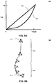
- FIGs. 8A-B describe in greater detail how the tilt functions described in FIGs. 7A-C may impact a swoop trajectory.
- FIG. 8A shows a chart 800 illustrating how the tilt of the camera corresponds to a distance to the target.
- Chart 800 shows two alternative tilt functions--a function 802 and a function 804.
- Function 802 has a linear correspondence between the camera tilt and the distance to target. Function 802 would result in a bowed swoop trajectory as illustrated in FIG. 1 .
- Function 804 is defined such that the tilt approaches 90 degrees more quickly as the virtual camera approaches the target location. As the camera tilts, the GIS client requests more data from the GIS server. By tilting more quickly as the camera gets close to the target, GIS client makes fewer data requests from the GIS server, thus saving computing resources. Moreover, having most of the tilt occur toward the end of the swoop trajectory may provide a more pleasing user experience. Function 804 may result in the swoop trajectory shown in FIG. 8B .
- FIG. 8B shows a diagram 850 illustrating an example swoop trajectory using tilt and distance functions described with respect to FIGs. 7A-C .
- Diagram 850 shows how a virtual camera travels along a swoop trajectory from a start location 812 to a target location 814.
- the swoop trajectory is described with respect to a first portion 802 and a second portion 804.
- the distance between the virtual camera and the target location decreases logarithmically.
- the virtual camera travels quickly through portion 802 of the swoop trajectory. This causes the user to travel through vast expanses of nearly empty space quickly. But, as the virtual camera approaches the target through portion 804, the virtual camera begins to slow down. Also at portion 804, the tilt approaches 90 degrees more quickly as the virtual camera approaches the target location.
- the server may alter the swoop trajectory according during high-traffic periods.
- the server may signal the client to further concentrate the tilt towards the end of the swoop trajectory.
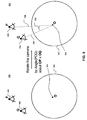
- FIG. 9 shows diagrams 900 and 950 illustrating a method for reducing roll, which may be used in step 306 in FIG. 3 .
- Diagram 900 shows a virtual camera at a first location 906 and a second location 908.
- the virtual camera is swooping towards a target on the surface of a model of the Earth 902.
- Model 902 is substantially spherical and has a center origin 904. As the virtual camera moves from location 906 to location 908 the curvature of the Earth causes roll. To compensate for the roll, the camera is rotated.
- Diagram 950 shows the virtual camera rotated to a location 952.
- Diagram 950 also shows a line segment 956 connecting origin 904 with a location 906 and a line segment 954 connecting origin 904 with location 952.
- the virtual camera is rotated by an angle 958 between line segment 954 and line segment 956.
- the virtual camera may be rotated approximately by angle 958.
- FIG. 10 shows diagrams 1000 and 1050 illustrating a method for restoring a screen space projection, which may be used in step 308 in FIG. 3 .
- Diagram 1000 shows a virtual camera with a focal point 1002 and a viewport 1004.
- Viewport 1004 corresponds to display area 202 in FIG. 2 .
- the virtual camera is on a swoop trajectory to a target with a location 1008 on the surface of a model 1022 of the Earth.
- Model 1022 of the Earth has a center origin 1024.
- the target was projected onto a position 1006 on viewport 1004. Due to rotating and repositioning that has occurred during the swoop trajectory, the target is now projected onto a position 1010 on viewport 1004. Changing the target's projection from position 1006 to 1010 can be disorienting to a user.
- model 1022 is rotated to restore the target's screen space projection.
- Diagram 1000 shows a line segment 1014 connecting target location 1008 with focal point 1002.
- Diagram 1000 also shows a line segment 1016 connecting focal point 1002 with position 1006 on viewport 1004.
- the Earth may be rotated around origin 1024 by approximately an angle 1012 between line segment 1014 and line segment 1016.
- the target's screen space projection is restored as illustrated in diagram 1050.
- the target is at a location 1052 that projects onto position 1006 on viewport 1004. Note that the target location is the same location on the model of the Earth after the rotation. However, the rotation of the model changed the target location relative to the virtual camera.
- FIGs. 11A-B show methods for adjusting for streaming terrain, which may be used in step 310 in FIG. 3 .
- the target location is determined by finding an intersection of a ray with a model of the Earth.
- the GIS client receives more detailed information regarding terrain on the model of the Earth.
- the intersection with the ray with the model may change.
- the target location may change due to streaming terrain data. Changing the target location due to streaming terrain data is illustrated in FIG. 11A .
- FIG. 11A shows a diagram 1100.
- Diagram 1100 shows a target location 1104 on a model of the Earth 1108. Target location 1104 is determined by finding an intersection between a ray and model 1108, as described with respect to FIG. 4 .
- Diagram 1100 also shows a virtual camera swooping in towards target location 1104. The virtual camera is at a location 1110 at a first point in time. The virtual camera is repositioned to a location 1112 at a second point in time. At a third point in time, the virtual camera is repositioned to a location 1114. At that point, data for terrain 1102 is streamed into the GIS client. The GIS client determines that target location 1104 is underneath terrain 1102. Thus, the target may be repositioned above terrain 1102.
- the target may be repositioned in several ways.
- a new target location may be determined by re-calculating an intersection of the ray and the model as in FIG. 4 .
- a new target location may be determined by increasing the elevation of the old target location to be above the terrain.
- Diagram 1110 shows a new target location 1106 determined by elevating target location 1104 by a distance 1116 to rise above terrain 1102.
- diagram 1100 shows the tilt of the virtual camera and the distance between the camera and the target is determined relative to target location 1104.
- the tilt of the virtual camera and the distance between the camera and the target is determined relative to target location 1106.
- the change in the tilt and distance values effect the calculations discussed with respect to FIGs. 7A-C that determine the swoop trajectory. For this reason, by changing the target location due to the streaming terrain, the swoop trajectory may be altered.
- FIG. 11B shows a diagram 1150 illustrating an alteration to a swoop trajectory due to a terrain collision.
- Diagram 1150 shows a virtual camera's swoop trajectory along a path 1162 to a target location 1158.
- the client may determine that a remainder of the trajectory 1154 collides with terrain 1152.
- the swoop trajectory may be recalculated to a trajectory 1156 to avoid colliding with terrain 1152.
- a GIS client may stream in new terrain dynamically during a swoop trajectory.
- An example GIS client is described in detail in FIG. 12 .
- FIG. 12 is an architecture diagram of an exemplary client 1200 of a GIS according to an embodiment of the invention.
- client 1200 includes a user interaction module 1210, local memory 1230, cache node manager 1240, renderer module 1250, network interface 1260, network loader 1265, and display interface 1280.
- user interaction module 1210 includes a graphical user interface (GUI) 1212 and motion model 1218.
- Local memory 1230 includes a view specification 1232 and quad node tree 1234.
- Cache node manager 1240 includes a retrieval list 1245.
- client 1200 can be implemented, for example, as software running on a client machine.
- Client 1200 interacts with a GIS server (not shown) to bring images of the Earth and other geospatial information/data to client 1200 for viewing by a user. Together, the images of the Earth and other geospatial data form a three dimensional model in a three dimensional environment.
- software objects are grouped according to functions that can run asynchronously (e.g., time independently) from one another.
- client 1200 operates as follows.
- User interaction module 1210 receives user input regarding a location that a user desires to view and, through motion model 1218, constructs view specification 1232.
- Renderer module 1250 uses view specification 1232 to decide what data is to be drawn and draws the data.
- Cache node manager 1240 runs in an asynchronous thread of control and builds a quad node tree 1234 by populating it with quad nodes retrieved from a remote server via a network.
- a user inputs location information using GUI 1212. This results, for example, in the generation of view specification 1232.
- View specification 1232 is placed in local memory 1230, where it is used by renderer module 1250.
- Motion model 1218 uses location information received via GUI 1212 to adjust the position and/or orientation of a virtual camera.
- the camera is used, for example, for viewing a displayed three dimensional model of the Earth. A user sees a displayed three dimensional model on his or her computer monitor from the standpoint of the virtual camera.
- motion model 1218 also determines view specification 1232 based on the position of the virtual camera, the orientation of the virtual camera, and the horizontal and vertical fields of view of the virtual camera.
- View specification 1232 defines the virtual camera's viewable volume within a three dimensional space, known as a frustum, and the position and orientation of the frustum with respect, for example, to a three dimensional map.
- the frustum is in the shape of a truncated pyramid.
- the frustum has minimum and maximum view distances that can change depending on the viewing circumstances.
- view specification 1232 changes.
- View specification 1232 is placed in local memory 1230, where it is used by renderer module 1250.
- view specification 1232 specifies three main parameter sets for the virtual camera: the camera tripod, the camera lens, and the camera focus capability.
- the camera tripod parameter set specifies the following: the virtual camera position: X, Y, Z (three coordinates); which way the virtual camera is oriented relative to a default orientation, such as heading angle (e.g., north?, south?, in-between?); pitch (e.g., level?, down?, up?, in-between?); and yaw/roll (e.g., level?, clockwise?, anti-clockwise?, in-between?).
- the lens parameter set specifies the following: horizontal field of view (e.g., telephoto?, normal human eye - about 55 degrees?, or wide-angle?); and vertical field of view (e.g., telephoto?, normal human eye - about 55 degrees?, or wide-angle?).
- the focus parameter set specifies the following: distance to the near-clip plane (e.g., how close to the "lens" can the virtual camera see, where objects closer are not drawn); and distance to the far-clip plane (e.g., how far from the lens can the virtual camera see, where objects further are not drawn).
- motion model 1218 implements such a ground level "pan the camera” type of control by adding (or subtracting) a small value (e.g., 1 degree per arrow key press) to the heading angle.
- the motion model 1218 would change the X, Y, Z coordinates of the virtual camera's position by first computing a unit-length vector along the view direction (HPR) and adding the X, Y, Z sub-components of this vector to the camera's position after scaling each sub-component by the desired speed of motion.
- motion model 1218 adjusts view specification 1232 by incrementally updating XYZ and HPR to define the "just after a move" new view position. In this way, motion model 1218 is responsible for navigating the virtual camera through the three dimensional environment.
- Motion module 1218 also conducts processing for swoop navigation.
- motion module 1218 includes several sub modules--a tilt calculator module 1290, target module 1292, positioner module 1294, roll compensator module 1294, terrain adjuster module 1298, screen space module 1288, and controller module 1286.
- Controller module 1286 activates the sub-modules to control the swoop navigation.
- the swoop navigation components may operate as described with respect to FIG. 3 .
- Target module 1292 determines a target.
- target module 1292 may operate as described to FIGs. 4-5 .
- Target module 1292 determines the target by first extending a ray from a focal point of the virtual camera through a point selected by a user. Then, target module 1292 determines an intersection between the ray and a three dimensional model as stored in quad node tree 1234. Finally, target module 1292 determines a target in the three dimensional model at the intersection.
- Tilt calculator module 1290 updates swoop parameters. Tilt calculator module 1290 performs distance, azimuth, and tilt calculations when activated. Tilt calculator module 1290 may be activated, for example, by a function call. When called, tilt calculator module 1290 first determines a distance between the virtual camera and the target in the three dimensional environment. Then, tilt calculator module 1290 determines a reduced distance. Tilt calculator module 1290 may reduce the distance logarithmically as described with respect to FIG. 7A . Finally, tilt calculator module 1290 determines a tilt as a function of the reduced distance. The tilt calculator may determine the tilt using an absolute tilt function (as described for FIG. 7B ) or an incremental tilt function (as described for FIG. 7C ).
- Tilt calculator module 1290 calculates tilt such that the tilt approaches 90 degrees more quickly as the virtual camera approaches the target. As the camera tilts, renderer module 1250 needs more data that is likely not cached in quad node tree 1234 in local memory. As result, cache node manager 1240 has to request more data from the GIS server. By tilting more quickly as the virtual camera approaches the target, cache node manager 1240 makes fewer data requests from the GIS server. Tilt calculator module 1290 may also calculate an azimuth as described above.
- positioner module 1294 When activated, positioner module 1294 repositions the virtual camera according to the target location determined by target module 1292 and the tilt and the reduced distance determined by tilt calculator module 1290. Positioner module 1294 may be activated, for example, by a function call. Positioner module 1294 may reposition the virtual camera by translating the virtual camera into the target, angling the virtual camera to match the tilt, and translating the virtual camera away from the target by the reduced distance. In one example, positioner module 1294 may operate as described with respect to steps 306-310 in FIG. 3 .
- roll compensator module 1296 rotates the camera to reduce roll.
- Roll compensator module 1296 may be activated, for example, by a function call.
- Roll compensator module 1296 may rotate the camera as described with respect to FIG. 9 .
- the target may change its screen space projection. Changing the target's screen space projection may be disorienting to a user.
- screen space module 1288 rotates the model of the Earth to restore the target's screen space projection. Screen space module 1288 may rotate the Earth as described with respect to FIG. 10 .
- renderer module 1250 requires more detailed model data, including terrain data.
- a request for more detailed geographic data is sent from cache node manager 1240 to the GIS server.
- the GIS server streams the more detailed geographic data, including terrain data back to GIS client 1200.
- Cache node manager 1240 saves the more detailed geographic data in quad node tree 1234.
- target module 1292 used the previous model in quad node tree 1230.
- terrain adjuster module 1298 may have to adjust the location of the target, as described with respect to FIG. 11A .
- terrain adjuster module 1298 may have to adjust the swoop trajectory as well, as described with respect to FIG. 11B .
- Terrain adjuster module 1298 may be activated, for example, by a function call.
- Renderer module 1250 has cycles corresponding to the display device's video refresh rate (e.g., 60 cycles per second). In one particular embodiment, renderer module 1250 performs a cycle of (i) waking up, (ii) reading the view specification 1232 that has been placed by motion model 1218 in a data structure accessed by a renderer, (iii) traversing quad node tree 1234 in local memory 1230, and (iv) drawing drawable data contained in the quad nodes residing in quad node tree 1234.
- the drawable data may be associated with a bounding box (e.g., a volume that contains the data or other such identifier). If present, the bounding box is inspected to see if the drawable data is potentially visible within view specification 1232. Potentially visible data is drawn, while data known not to be visible is ignored.
- the renderer uses view specification 1232 to determine whether the drawable payload of a quad node resident in quad node tree 1234 is not to be drawn, as will now be more fully explained.
- Quad node tree 1234 is the data source for the drawing that renderer 1250 does except for this star field.
- Renderer module 1250 traverses quad node tree 1234 by attempting to access each quad node resident in quad node tree 1234.
- Each quad node is a data structure that has up to four references and an optional payload of data.
- renderer module 1250 will compare the bounding box of the payload (if any) against view specification 1232, drawing it so long as the drawable data is not wholly outside the frustum and is not considered inappropriate to draw based on other factors. These other factors may include, for example, distance from the camera, tilt, or other such considerations. If the payload is not wholly outside the frustum and is not considered inappropriate to draw, renderer module 1250 also attempts to access each of the up to four references in the quad node.
- renderer module 1250 will attempt to access any drawable data in that other quad node and also potentially attempt to access any of the up to four references in that other quad node.
- the renderer module's attempts to access each of the up to four references of a quad node are detected by the quad node itself.
- a quad node is a data structure that may have a payload of data and up to four references to other files, each of which in turn may be a quad node.
- the files referenced by a quad node are referred to herein as the children of that quad node, and the referencing quad node is referred to herein as the parent.
- a file contains not only the referenced child, but descendants of that child as well. These aggregates are known as cache nodes and may include several quad nodes. Such aggregation takes place in the course of database construction.
- the payload of data is empty.
- Each of the references to other files comprises, for instance, a filename and a corresponding address in local memory for that file, if any.
- the referenced files are all stored on one or more remote servers (e.g., on server(s) of the GIS), and there is no drawable data present on the user's computer.
- Quad nodes and cache nodes have built-in accessor functions. As previously explained, the renderer module's attempts to access each of the up to four references of a quad node are detected by the quad node itself. Upon the renderer module's attempt to access a child quad node that has a filename but no corresponding address, the parent quad node places (e.g., by operation of its accessor function) that filename onto a cache node retrieval list 1245.
- the cache node retrieval list comprises a list of information identifying cache nodes to be downloaded from a GIS server. If a child of a quad node has a local address that is not null, the renderer module 1250 uses that address in local memory 1230 to access the child quad node.
- Quad nodes are configured so that those with drawable payloads may include within their payload a bounding box or other location identifier.
- Renderer module 1250 performs a view frustum cull, which compares the bounding box/location identifier of the quad node payload (if present) with view specification 1232. If the bounding box is completely disjoint from view specification 1232 (e.g., none of the drawable data is within the frustum), the payload of drawable data will not be drawn, even though it was already retrieved from a GIS server and stored on the user's computer. Otherwise, the drawable data is drawn.
- the view frustum cull determines whether or not the bounding box (if any) of the quad node payload is completely disjoint from view specification 1232 before renderer module 1250 traverses the children of that quad node. If the bounding box of the quad node is completely disjoint from view specification 1232, renderer module 1250 does not attempt to access the children of that quad node. A child quad node never extends beyond the bounding box of its parent quad node. Thus, once the view frustum cull determines that a parent quad node is completely disjoint from the view specification, it can be assumed that all progeny of that quad node are also completely disjoint from view specification 1232.
- Quad node and cache node payloads may contain data of various types.
- cache node payloads can contain satellite images, text labels, political boundaries, 3 dimensional vertices along with point, line or polygon connectivity for rendering roads, and other types of data.
- the amount of data in any quad node payload is limited to a maximum value. However, in some cases, the amount of data needed to describe an area at a particular resolution exceeds this maximum value. In those cases, such as processing vector data, some of the data is contained in the parent payload and the rest of the data at the same resolution is contained in the payloads of the children (and possibly even within the children's descendents). There also may be cases in which children may contain data of either higher resolution or the same resolution as their parent. For example, a parent node might have two children of the same resolution as that parent, and two additional children of different resolutions (e.g., higher) than that parent.
- the cache node manager 1240 thread and each of one or more network loader 1265 threads, operate asynchronously from renderer module 1250 and user interaction module 1210. Renderer module 1250 and user interaction module 1210 can also operate asynchronously from each other. In some embodiments, as many as eight network loader 1265 threads are independently executed, each operating asynchronously from renderer module 1250 and user interaction module 1210.
- the cache node manager 1240 thread builds quad node tree 1234 in local memory 1230 by populating it with quad nodes retrieved from GIS server(s). Quad node tree 1234 begins with a root node when the client system is launched or otherwise started. The root node contains a filename (but no corresponding address) and no data payload. As previously described, this root node uses a built-in accessor function to self-report to the cache node retrieval list 1245 after it has been traversed by renderer module 1250 for the first time.
- a network loader traverses the cache node retrieval list 1245 (which in the embodiment shown in FIG. 12 is included in cache node manager 1240, but can also be located in other places, such as the local memory 1230 or other storage facility) and requests the next cache node from the GIS server(s) using the cache node's filename.
- the network loader only requests files that appear on the cache node retrieval list.
- Cache node manager 1240 allocates space in local memory 1230 (or other suitable storage facility) for the returned file, which is organized into one or more new quad nodes that are descendents of the parent quad node.
- Cache node manager 1240 can also decrypt or decompress the data file returned from the GIS server(s), if necessary (e.g., to complement any encryption or compression on the server-side). Cache node manager 1240 updates the parent quad node in quad node tree 1234 with the address corresponding to the local memory 1230 address for each newly constructed child quad node.
- renderer module 1250 upon its next traversal of quad node tree 1234 and traversal of the updated parent quad node, renderer module 1250 finds the address in local memory corresponding to the child quad node and can access the child quad node. The renderer's traversal of the child quad node progresses according to the same steps that are followed for the parent quad node. This continues through quad node tree 1234 until a node is reached that is completely disjoint from view specification 1232 or is considered inappropriate to draw based on other factors as previously explained.
- Network interface 1260 e.g., a network interface card or transceiver
- Network interface 1260 is configured to allow communications from the client to be sent over a network, and to allow communications from the remote server(s) to be received by the client.
- display interface 1280 (e.g., a display interface card) is configured to allow data from a mapping module to be sent to a display associated with the user's computer, so that the user can view the data.
- display interface 1280 e.g., a display interface card
- network interface 1260 and display interface 1280 can be implemented with conventional technology.
Landscapes
- Engineering & Computer Science (AREA)
- Physics & Mathematics (AREA)
- Theoretical Computer Science (AREA)
- General Physics & Mathematics (AREA)
- Computer Graphics (AREA)
- Geometry (AREA)
- Software Systems (AREA)
- Computing Systems (AREA)
- Remote Sensing (AREA)
- Radar, Positioning & Navigation (AREA)
- Computer Hardware Design (AREA)
- General Engineering & Computer Science (AREA)
- Processing Or Creating Images (AREA)
- Instructional Devices (AREA)
Claims (9)
- Procédé exécuté par ordinateur pour la navigation d'une caméra virtuelle dans un environnement tridimensionnel, l'environnement tridimensionnel comprenant un modèle tridimensionnel de la Terre, dans lequel la caméra virtuelle précise une vue de l'environnement tridimensionnel, comprenant :A : la détermination (302) d'un emplacement cible par rapport au modèle tridimensionnel de la Terre dans l'environnement tridimensionnel, la caméra virtuelle se trouvant dans une première position pour capturer une vue verticale du modèle tridimensionnel de la Terre, dans lequel le modèle tridimensionnel de la Terre est courbe ;B : la détermination d'une distance entre un premier emplacement de la caméra virtuelle et l'emplacement cible dans l'environnement tridimensionnel,C : la détermination d'une distance réduite par rapport à la distance déterminée dans l'étape (B) ;D : la détermination d'une inclinaison comme une fonction de la distance réduite, dans laquelle la fonction est définie de façon à ce que l'inclinaison s'approche de 90 degrés lorsque la distance réduite s'approche de zéro, l'inclinaison définissant un angle par rapport à un vecteur ascendant depuis l'emplacement cible ;E : le repositionnement (304) de la caméra virtuelle à un deuxième emplacement, le repositionnement étant réalisé en fonction de l'inclination, de la distance réduite et de l'emplacement cible, dans lequel le repositionnement comprend la rotation de la caméra pour réduire ou éliminer le roulement causé par la courbure du modèle tridimensionnel de la Terre, dans lequel la rotation de la caméra comprend la rotation de la caméra d'un angle entre un premier segment de droite unissant le premier emplacement et un centre du modèle de la Terre et un deuxième segment de droite unissant le deuxième emplacement et le centre du modèle de la Terre ;F : la rotation du modèle tridimensionnel de la Terre dans l'environnement tridimensionnel de façon à ce que l'emplacement cible se projette sur le même point dans une fenêtre d'affichage de la caméra virtuelle lorsque la caméra virtuelle se trouve sur le premier emplacement et le deuxième emplacement, dans lequel le modèle de la Terre est soumis à une rotation d'un angle compris entre le premier segment de droite et le deuxième segment de droite dans la direction de l'inclinaison ; etG : la répétition des étapes B à F jusqu'à ce que la distance entre la caméra virtuelle et l'emplacement cible se trouve en dessous d'un seuil pour transférer la caméra virtuelle de la première position pour capturer la vue verticale du modèle tridimensionnel de la Terre vers une deuxième position pour capturer une vue horizontale du modèle tridimensionnel de la Terre, la deuxième position étant plus proche du modèle tridimensionnel de la Terre que la première position.
- Procédé selon la revendication 1, dans lequel l'étape A comprend :l'extension d'un rayon depuis un point focal de la caméra virtuelle à travers un point sélectionné par un utilisateur ;la détermination d'une intersection entre le rayon et le modèle tridimensionnel de la Terre dans l'environnement tridimensionnel ; etla détermination de l'emplacement cible en fonction de la position de l'intersection.
- Procédé selon la revendication 1, comprenant en outre :H : le repositionnement de la caméra virtuelle de façon à ce que la position de la caméra virtuelle se trouve au-dessus du terrain dans le modèle tridimensionnel de la Terre dans l'environnement tridimensionnel ;et dans lequel l'étape G comprend la répétition des étapes B à F jusqu'à ce que la distance entre la caméra virtuelle et l'emplacement cible se trouve en dessous d'un seuil.
- Système de navigation d'une caméra virtuelle dans un environnement tridimensionnel, l'environnement tridimensionnel comprenant un modèle tridimensionnel de la Terre, le système comprenant :un moyen de ciblage (1292) pour la détermination d'un emplacement cible par rapport au modèle tridimensionnel de la Terre dans l'environnement tridimensionnel, la caméra virtuelle se trouvant dans une première position pour capturer une vue verticale du modèle tridimensionnel de la Terre, dans lequel le modèle tridimensionnel de la Terre est courbe ;un moyen de calcul de l'inclinaison (1290) pour, lorsqu'il est activé :déterminer une distance entre un premier emplacement de la caméra virtuelle et l'emplacement cible dans l'environnement tridimensionnel,déterminer une distance réduite par rapport à la distance entre le premier emplacement de la caméra virtuelle et la caméra cible etdéterminer une inclinaison en tant que fonction de la distance réduite, où la fonction est définie de façon à ce que l'inclinaison s'approche de 90 degrés lorsque la distance réduite s'approche de zéro, l'inclinaison définissant un angle par rapport à un vecteur ascendant depuis l'emplacement cible ;un moyen de positionnement (1294) pour, lorsqu'il est activé, repositionner la caméra virtuelle à un deuxième emplacement, le repositionnement étant réalisé en fonction de l'inclinaison, de la distance réduite et de l'emplacement cible,un moyen de compensation du roulement pour la rotation de la caméra afin de réduire ou d'éliminer le roulement causé par la courbure du modèle tridimensionnel de la Terre, le moyen de compensation du roulement étant configuré pour mettre en rotation la caméra d'un angle entre un premier segment de droite unissant le premier emplacement et un centre du modèle de la Terre et un deuxième segment de droite unissant le deuxième emplacement et le centre du modèle de la Terre ;un moyen pour l'espacement de l'écran pour la rotation du modèle tridimensionnel de la Terre dans l'environnement tridimensionnel de façon à ce que les emplacements cibles se projettent sur le même point dans une fenêtre d'affichage de la caméra virtuelle lorsque la caméra virtuelle se trouve au premier emplacement et au deuxième emplacement, le moyen pour l'espacement de l'écran étant configuré pour la rotation du modèle de la Terre d'un angle entre le premier segment de droite et le deuxième segment de droite dans le sens de l'inclinaison ;un moyen de contrôle (1286) pour activer de manière répétée le moyen de calcul de l'inclinaison, le moyen de positionnement, le moyen de compensation du roulement et le moyen d'espacement de l'écran jusqu'à ce que la distance entre la caméra virtuelle et l'emplacement cible se trouve en dessous d'un seuil, de sorte que la caméra virtuelle est transférée de la première position pour capturer la vue verticale du modèle tridimensionnel de la Terre vers une deuxième position pour capturer une vue horizontale du modèle tridimensionnel de la Terre, la deuxième position étant plus proche du modèle tridimensionnel de la Terre que la première position.
- Système selon la revendication 4, dans lequel la fonction utilisée par le moyen de calcul de l'inclinaison pour déterminer l'inclinaison est définie de façon à ce que l'inclinaison s'approche de 90 degrés plus rapidement lorsque la distance diminue.
- Système selon la revendication 5, dans lequel le moyen de positionnement fait une translation de la caméra virtuelle vers la cible, oriente la caméra virtuelle de façon à égaler l'inclinaison et éloigne la caméra virtuelle par une translation égale à la distance réduite de l'emplacement cible.
- Système selon la revendication 6, dans lequel le moyen de ciblage étend un rayon depuis un point focal de la caméra virtuelle à travers un point sélectionné par un utilisateur, détermine une intersection entre le rayon et le modèle tridimensionnel de la Terre dans l'environnement tridimensionnel, et détermine un emplacement cible en fonction de l'intersection.
- Système selon la revendication 10, comprenant en outre un moyen d'ajustement du terrain (1298) pour, lorsqu'il est activé, repositionner la caméra virtuelle de façon à ce que la position de la caméra virtuelle se trouve au-dessus du terrain dans le modèle tridimensionnel de la Terre dans l'environnement tridimensionnel,
dans lequel le moyen de contrôle active de manière répétée le moyen d'ajustement du terrain jusqu'à ce que la distance entre la caméra virtuelle et la cible soit inférieure à un seuil. - Support pouvant être lu par un ordinateur contenant un code pouvant être lu par un ordinateur pour contrôler un ordinateur afin d'exécuter le procédé selon l'une quelconque des revendications 1 à 3.
Applications Claiming Priority (2)
| Application Number | Priority Date | Filing Date | Title |
|---|---|---|---|
| US4474408P | 2008-04-14 | 2008-04-14 | |
| PCT/US2009/002309 WO2009128899A1 (fr) | 2008-04-14 | 2009-04-14 | Navigation tridimensionnelle |
Publications (2)
| Publication Number | Publication Date |
|---|---|
| EP2279497A1 EP2279497A1 (fr) | 2011-02-02 |
| EP2279497B1 true EP2279497B1 (fr) | 2016-02-10 |
Family
ID=40823391
Family Applications (1)
| Application Number | Title | Priority Date | Filing Date |
|---|---|---|---|
| EP09731588.1A Not-in-force EP2279497B1 (fr) | 2008-04-14 | 2009-04-14 | Navigation tridimensionnelle |
Country Status (8)
| Country | Link |
|---|---|
| US (1) | US20090259976A1 (fr) |
| EP (1) | EP2279497B1 (fr) |
| JP (1) | JP5507541B2 (fr) |
| KR (1) | KR101580979B1 (fr) |
| CN (1) | CN102067179A (fr) |
| AU (1) | AU2009236690B2 (fr) |
| CA (1) | CA2721219A1 (fr) |
| WO (1) | WO2009128899A1 (fr) |
Families Citing this family (34)
| Publication number | Priority date | Publication date | Assignee | Title |
|---|---|---|---|---|
| KR101534789B1 (ko) * | 2008-05-28 | 2015-07-07 | 구글 인코포레이티드 | 모바일 컴퓨팅 디바이스에서의 모션-컨트롤 뷰 |
| CN102187309A (zh) * | 2008-08-22 | 2011-09-14 | 谷歌公司 | 移动设备上的三维环境中的导航 |
| USD616462S1 (en) * | 2009-03-30 | 2010-05-25 | Smart Technologies Ulc | Icon for a portion of a display screen |
| US8665259B2 (en) * | 2009-04-16 | 2014-03-04 | Autodesk, Inc. | Multiscale three-dimensional navigation |
| US8665260B2 (en) * | 2009-04-16 | 2014-03-04 | Autodesk, Inc. | Multiscale three-dimensional navigation |
| US8933925B2 (en) * | 2009-06-15 | 2015-01-13 | Microsoft Corporation | Piecewise planar reconstruction of three-dimensional scenes |
| USD644656S1 (en) * | 2010-06-11 | 2011-09-06 | Microsoft Corporation | Display screen with a user interface |
| CN102313554B (zh) * | 2010-06-30 | 2014-04-16 | 株式会社电装 | 车载导航系统 |
| US8780174B1 (en) | 2010-10-12 | 2014-07-15 | The Boeing Company | Three-dimensional vision system for displaying images taken from a moving vehicle |
| USD654930S1 (en) * | 2010-11-17 | 2012-02-28 | Microsoft Corporation | Display screen with an animated user interface |
| WO2012071450A1 (fr) * | 2010-11-24 | 2012-05-31 | Google Inc. | Planification de trajet pour la navigation dans des rues dans un environnement tridimensionnel, et applications associées |
| US8675049B2 (en) | 2011-06-09 | 2014-03-18 | Microsoft Corporation | Navigation model to render centered objects using images |
| US20150178972A1 (en) * | 2011-06-14 | 2015-06-25 | Google Inc. | Animated Visualization of GPS Data in a GIS System |
| US9508002B2 (en) * | 2011-06-14 | 2016-11-29 | Google Inc. | Generating cinematic flyby sequences following paths and GPS tracks |
| US8890863B1 (en) * | 2011-08-12 | 2014-11-18 | Google Inc. | Automatic method for photo texturing geolocated 3-D models from geolocated imagery |
| US9189891B2 (en) * | 2011-08-16 | 2015-11-17 | Google Inc. | Systems and methods for navigating a camera |
| US8994738B1 (en) | 2011-10-04 | 2015-03-31 | Google Inc. | Systems and method for navigating between oblique views of a map |
| US9019279B1 (en) | 2011-10-04 | 2015-04-28 | Google Inc. | Systems and method for navigating between a nadir view and an oblique view of a map |
| US8767011B1 (en) * | 2011-10-17 | 2014-07-01 | Google Inc. | Culling nodes over a horizon using conical volumes |
| US20130293683A1 (en) * | 2012-05-03 | 2013-11-07 | Harman International (Shanghai) Management Co., Ltd. | System and method of interactively controlling a virtual camera |
| US9092900B2 (en) * | 2012-06-05 | 2015-07-28 | Google Inc. | Terrain-based virtual camera tilting, and applications thereof |
| US8650220B2 (en) | 2012-06-05 | 2014-02-11 | Google Inc. | System and method for storing and retrieving geospatial data |
| US9025860B2 (en) | 2012-08-06 | 2015-05-05 | Microsoft Technology Licensing, Llc | Three-dimensional object browsing in documents |
| EP2911393B1 (fr) * | 2012-10-16 | 2018-06-06 | Jae Woong Jeon | Procédé et système pour commander une caméra virtuelle dans un espace virtuel en 3d, et support d'enregistrement lisible par un ordinateur |
| US20150062114A1 (en) * | 2012-10-23 | 2015-03-05 | Andrew Ofstad | Displaying textual information related to geolocated images |
| KR102079332B1 (ko) * | 2013-01-24 | 2020-02-19 | 주식회사 케이에스에스이미지넥스트 | 3d 차량 주변 영상 생성 방법 및 시스템 |
| US10140765B2 (en) * | 2013-02-25 | 2018-11-27 | Google Llc | Staged camera traversal for three dimensional environment |
| US10108882B1 (en) * | 2015-05-16 | 2018-10-23 | Sturfee, Inc. | Method to post and access information onto a map through pictures |
| US9679413B2 (en) | 2015-08-13 | 2017-06-13 | Google Inc. | Systems and methods to transition between viewpoints in a three-dimensional environment |
| US9619714B2 (en) * | 2015-09-10 | 2017-04-11 | Sony Corporation | Device and method for video generation |
| US9684993B2 (en) * | 2015-09-23 | 2017-06-20 | Lucasfilm Entertainment Company Ltd. | Flight path correction in virtual scenes |
| CN108984087B (zh) * | 2017-06-02 | 2021-09-14 | 腾讯科技(深圳)有限公司 | 基于三维虚拟形象的社交互动方法及装置 |
| WO2020230249A1 (fr) * | 2019-05-13 | 2020-11-19 | 日本電信電話株式会社 | Dispositif d'affichage à passage, procédé d'affichage à passage, et programme d'affichage à passage |
| CN110211177A (zh) * | 2019-06-05 | 2019-09-06 | 视云融聚(广州)科技有限公司 | 摄像画面线性目标指北方法、电子设备及存储介质 |
Family Cites Families (24)
| Publication number | Priority date | Publication date | Assignee | Title |
|---|---|---|---|---|
| JPH03240156A (ja) * | 1990-02-16 | 1991-10-25 | Toshiba Corp | データ処理システム |
| US5276785A (en) * | 1990-08-02 | 1994-01-04 | Xerox Corporation | Moving viewpoint with respect to a target in a three-dimensional workspace |
| DE69629917D1 (de) * | 1995-12-07 | 2003-10-16 | Sega Enterprises Kk | Bilderzeugungsapparat, bilderzeugungsverfahren, spielmaschine für das verfahren und medium |
| ES2332271T3 (es) * | 1996-06-05 | 2010-02-01 | Kabushiki Kaisha Sega Doing Business As Sega Corporation | Dispositivo de procesamiento de graficos, metodo de procesamiento de graficos, maquina de juegos y medio de almacenamiento. |
| JP3968586B2 (ja) * | 1996-06-05 | 2007-08-29 | 株式会社セガ | ゲーム装置、画像処理方法、及び記録媒体 |
| GB2320232B (en) * | 1996-12-12 | 2000-09-27 | Ico Services Ltd | Satellite and Method of Operating a Satellite |
| JP3547947B2 (ja) * | 1997-08-11 | 2004-07-28 | アルパイン株式会社 | ナビゲーション装置における所在階数表示方法 |
| GB9800397D0 (en) * | 1998-01-09 | 1998-03-04 | Philips Electronics Nv | Virtual environment viewpoint control |
| JP2000135375A (ja) * | 1998-10-30 | 2000-05-16 | Square Co Ltd | ゲーム装置、情報記録媒体および画像処理方法 |
| JP3301420B2 (ja) * | 1999-05-12 | 2002-07-15 | 株式会社デンソー | 地図表示装置 |
| US6556206B1 (en) * | 1999-12-09 | 2003-04-29 | Siemens Corporate Research, Inc. | Automated viewpoint selection for 3D scenes |
| JP2001195608A (ja) * | 2000-01-14 | 2001-07-19 | Artdink:Kk | Cgの三次元表示方法 |
| EP1363246A4 (fr) * | 2001-02-23 | 2006-11-08 | Fujitsu Ltd | Dispositif de commande d'affichage, dispositif terminal d'information equipe de ce dispositif de commande d'affichage, et dispositif de commande de position de point de vue |
| JP4183441B2 (ja) * | 2002-05-21 | 2008-11-19 | 株式会社キャドセンター | 3次元データ処理システム、3次元データ処理方法、並びにコンピュータ上で動作する情報処理プログラム |
| US7042449B2 (en) * | 2002-06-28 | 2006-05-09 | Autodesk Canada Co. | Push-tumble three dimensional navigation system |
| US8044953B2 (en) * | 2002-06-28 | 2011-10-25 | Autodesk, Inc. | System for interactive 3D navigation for proximal object inspection |
| JP2004108856A (ja) * | 2002-09-17 | 2004-04-08 | Clarion Co Ltd | ナビゲーション装置、及び該装置における地図表示方法 |
| US7933929B1 (en) * | 2005-06-27 | 2011-04-26 | Google Inc. | Network link for providing dynamic data layer in a geographic information system |
| AU2005203074A1 (en) * | 2005-07-14 | 2007-02-01 | Canon Information Systems Research Australia Pty Ltd | Image browser |
| JP5075330B2 (ja) * | 2005-09-12 | 2012-11-21 | 任天堂株式会社 | 情報処理プログラム |
| US7613566B1 (en) * | 2005-09-13 | 2009-11-03 | Garmin Ltd. | Navigation device with improved zoom functions |
| US7707516B2 (en) * | 2006-05-26 | 2010-04-27 | Google Inc. | Embedded navigation interface |
| US20080062173A1 (en) * | 2006-09-13 | 2008-03-13 | Eric Tashiro | Method and apparatus for selecting absolute location on three-dimensional image on navigation display |
| US8089479B2 (en) * | 2008-04-11 | 2012-01-03 | Apple Inc. | Directing camera behavior in 3-D imaging system |
-
2009
- 2009-04-14 EP EP09731588.1A patent/EP2279497B1/fr not_active Not-in-force
- 2009-04-14 CN CN2009801213816A patent/CN102067179A/zh active Pending
- 2009-04-14 WO PCT/US2009/002309 patent/WO2009128899A1/fr not_active Ceased
- 2009-04-14 KR KR1020107025474A patent/KR101580979B1/ko active Active
- 2009-04-14 CA CA2721219A patent/CA2721219A1/fr not_active Abandoned
- 2009-04-14 AU AU2009236690A patent/AU2009236690B2/en not_active Ceased
- 2009-04-14 JP JP2011505013A patent/JP5507541B2/ja not_active Expired - Fee Related
- 2009-04-14 US US12/423,434 patent/US20090259976A1/en not_active Abandoned
Also Published As
| Publication number | Publication date |
|---|---|
| CA2721219A1 (fr) | 2009-10-22 |
| EP2279497A1 (fr) | 2011-02-02 |
| US20090259976A1 (en) | 2009-10-15 |
| WO2009128899A1 (fr) | 2009-10-22 |
| JP2011519085A (ja) | 2011-06-30 |
| AU2009236690A1 (en) | 2009-10-22 |
| CN102067179A (zh) | 2011-05-18 |
| KR20100137001A (ko) | 2010-12-29 |
| KR101580979B1 (ko) | 2015-12-30 |
| JP5507541B2 (ja) | 2014-05-28 |
| AU2009236690B2 (en) | 2014-10-23 |
Similar Documents
| Publication | Publication Date | Title |
|---|---|---|
| EP2279497B1 (fr) | Navigation tridimensionnelle | |
| EP2297704B1 (fr) | Translation panoramique à l aide de surfaces virtuelles | |
| US9024947B2 (en) | Rendering and navigating photographic panoramas with depth information in a geographic information system | |
| EP2643822B1 (fr) | Aide à la navigation parmi des panoramas géolocalisés | |
| US9626790B1 (en) | View-dependent textures for interactive geographic information system | |
| US10140765B2 (en) | Staged camera traversal for three dimensional environment | |
| US9165397B2 (en) | Texture blending between view-dependent texture and base texture in a geographic information system | |
| US9092900B2 (en) | Terrain-based virtual camera tilting, and applications thereof |
Legal Events
| Date | Code | Title | Description |
|---|---|---|---|
| PUAI | Public reference made under article 153(3) epc to a published international application that has entered the european phase |
Free format text: ORIGINAL CODE: 0009012 |
|
| 17P | Request for examination filed |
Effective date: 20101115 |
|
| AK | Designated contracting states |
Kind code of ref document: A1 Designated state(s): AT BE BG CH CY CZ DE DK EE ES FI FR GB GR HR HU IE IS IT LI LT LU LV MC MK MT NL NO PL PT RO SE SI SK TR |
|
| AX | Request for extension of the european patent |
Extension state: AL BA RS |
|
| DAX | Request for extension of the european patent (deleted) | ||
| 17Q | First examination report despatched |
Effective date: 20130610 |
|
| GRAJ | Information related to disapproval of communication of intention to grant by the applicant or resumption of examination proceedings by the epo deleted |
Free format text: ORIGINAL CODE: EPIDOSDIGR1 |
|
| GRAP | Despatch of communication of intention to grant a patent |
Free format text: ORIGINAL CODE: EPIDOSNIGR1 |
|
| GRAP | Despatch of communication of intention to grant a patent |
Free format text: ORIGINAL CODE: EPIDOSNIGR1 |
|
| INTG | Intention to grant announced |
Effective date: 20150305 |
|
| GRAP | Despatch of communication of intention to grant a patent |
Free format text: ORIGINAL CODE: EPIDOSNIGR1 |
|
| INTG | Intention to grant announced |
Effective date: 20150723 |
|
| GRAS | Grant fee paid |
Free format text: ORIGINAL CODE: EPIDOSNIGR3 |
|
| GRAA | (expected) grant |
Free format text: ORIGINAL CODE: 0009210 |
|
| AK | Designated contracting states |
Kind code of ref document: B1 Designated state(s): AT BE BG CH CY CZ DE DK EE ES FI FR GB GR HR HU IE IS IT LI LT LU LV MC MK MT NL NO PL PT RO SE SI SK TR |
|
| REG | Reference to a national code |
Ref country code: GB Ref legal event code: FG4D |
|
| REG | Reference to a national code |
Ref country code: AT Ref legal event code: REF Ref document number: 774984 Country of ref document: AT Kind code of ref document: T Effective date: 20160215 Ref country code: CH Ref legal event code: EP |
|
| REG | Reference to a national code |
Ref country code: IE Ref legal event code: FG4D |
|
| REG | Reference to a national code |
Ref country code: DE Ref legal event code: R096 Ref document number: 602009036180 Country of ref document: DE |
|
| REG | Reference to a national code |
Ref country code: FR Ref legal event code: PLFP Year of fee payment: 8 |
|
| REG | Reference to a national code |
Ref country code: LT Ref legal event code: MG4D |
|
| REG | Reference to a national code |
Ref country code: NL Ref legal event code: MP Effective date: 20160210 |
|
| REG | Reference to a national code |
Ref country code: AT Ref legal event code: MK05 Ref document number: 774984 Country of ref document: AT Kind code of ref document: T Effective date: 20160210 |
|
| PG25 | Lapsed in a contracting state [announced via postgrant information from national office to epo] |
Ref country code: FI Free format text: LAPSE BECAUSE OF FAILURE TO SUBMIT A TRANSLATION OF THE DESCRIPTION OR TO PAY THE FEE WITHIN THE PRESCRIBED TIME-LIMIT Effective date: 20160210 Ref country code: HR Free format text: LAPSE BECAUSE OF FAILURE TO SUBMIT A TRANSLATION OF THE DESCRIPTION OR TO PAY THE FEE WITHIN THE PRESCRIBED TIME-LIMIT Effective date: 20160210 Ref country code: NO Free format text: LAPSE BECAUSE OF FAILURE TO SUBMIT A TRANSLATION OF THE DESCRIPTION OR TO PAY THE FEE WITHIN THE PRESCRIBED TIME-LIMIT Effective date: 20160510 Ref country code: IT Free format text: LAPSE BECAUSE OF FAILURE TO SUBMIT A TRANSLATION OF THE DESCRIPTION OR TO PAY THE FEE WITHIN THE PRESCRIBED TIME-LIMIT Effective date: 20160210 Ref country code: GR Free format text: LAPSE BECAUSE OF FAILURE TO SUBMIT A TRANSLATION OF THE DESCRIPTION OR TO PAY THE FEE WITHIN THE PRESCRIBED TIME-LIMIT Effective date: 20160511 Ref country code: ES Free format text: LAPSE BECAUSE OF FAILURE TO SUBMIT A TRANSLATION OF THE DESCRIPTION OR TO PAY THE FEE WITHIN THE PRESCRIBED TIME-LIMIT Effective date: 20160210 |
|
| PG25 | Lapsed in a contracting state [announced via postgrant information from national office to epo] |
Ref country code: IS Free format text: LAPSE BECAUSE OF FAILURE TO SUBMIT A TRANSLATION OF THE DESCRIPTION OR TO PAY THE FEE WITHIN THE PRESCRIBED TIME-LIMIT Effective date: 20160610 Ref country code: NL Free format text: LAPSE BECAUSE OF FAILURE TO SUBMIT A TRANSLATION OF THE DESCRIPTION OR TO PAY THE FEE WITHIN THE PRESCRIBED TIME-LIMIT Effective date: 20160210 Ref country code: PL Free format text: LAPSE BECAUSE OF FAILURE TO SUBMIT A TRANSLATION OF THE DESCRIPTION OR TO PAY THE FEE WITHIN THE PRESCRIBED TIME-LIMIT Effective date: 20160210 Ref country code: PT Free format text: LAPSE BECAUSE OF FAILURE TO SUBMIT A TRANSLATION OF THE DESCRIPTION OR TO PAY THE FEE WITHIN THE PRESCRIBED TIME-LIMIT Effective date: 20160613 Ref country code: LT Free format text: LAPSE BECAUSE OF FAILURE TO SUBMIT A TRANSLATION OF THE DESCRIPTION OR TO PAY THE FEE WITHIN THE PRESCRIBED TIME-LIMIT Effective date: 20160210 Ref country code: BE Free format text: LAPSE BECAUSE OF NON-PAYMENT OF DUE FEES Effective date: 20160430 Ref country code: AT Free format text: LAPSE BECAUSE OF FAILURE TO SUBMIT A TRANSLATION OF THE DESCRIPTION OR TO PAY THE FEE WITHIN THE PRESCRIBED TIME-LIMIT Effective date: 20160210 Ref country code: SE Free format text: LAPSE BECAUSE OF FAILURE TO SUBMIT A TRANSLATION OF THE DESCRIPTION OR TO PAY THE FEE WITHIN THE PRESCRIBED TIME-LIMIT Effective date: 20160210 Ref country code: LV Free format text: LAPSE BECAUSE OF FAILURE TO SUBMIT A TRANSLATION OF THE DESCRIPTION OR TO PAY THE FEE WITHIN THE PRESCRIBED TIME-LIMIT Effective date: 20160210 |
|
| PGFP | Annual fee paid to national office [announced via postgrant information from national office to epo] |
Ref country code: FR Payment date: 20160425 Year of fee payment: 8 |
|
| PG25 | Lapsed in a contracting state [announced via postgrant information from national office to epo] |
Ref country code: EE Free format text: LAPSE BECAUSE OF FAILURE TO SUBMIT A TRANSLATION OF THE DESCRIPTION OR TO PAY THE FEE WITHIN THE PRESCRIBED TIME-LIMIT Effective date: 20160210 Ref country code: DK Free format text: LAPSE BECAUSE OF FAILURE TO SUBMIT A TRANSLATION OF THE DESCRIPTION OR TO PAY THE FEE WITHIN THE PRESCRIBED TIME-LIMIT Effective date: 20160210 |
|
| REG | Reference to a national code |
Ref country code: DE Ref legal event code: R097 Ref document number: 602009036180 Country of ref document: DE |
|
| PG25 | Lapsed in a contracting state [announced via postgrant information from national office to epo] |
Ref country code: RO Free format text: LAPSE BECAUSE OF FAILURE TO SUBMIT A TRANSLATION OF THE DESCRIPTION OR TO PAY THE FEE WITHIN THE PRESCRIBED TIME-LIMIT Effective date: 20160210 Ref country code: SK Free format text: LAPSE BECAUSE OF FAILURE TO SUBMIT A TRANSLATION OF THE DESCRIPTION OR TO PAY THE FEE WITHIN THE PRESCRIBED TIME-LIMIT Effective date: 20160210 Ref country code: CZ Free format text: LAPSE BECAUSE OF FAILURE TO SUBMIT A TRANSLATION OF THE DESCRIPTION OR TO PAY THE FEE WITHIN THE PRESCRIBED TIME-LIMIT Effective date: 20160210 |
|
| REG | Reference to a national code |
Ref country code: CH Ref legal event code: PL |
|
| PLBE | No opposition filed within time limit |
Free format text: ORIGINAL CODE: 0009261 |
|
| STAA | Information on the status of an ep patent application or granted ep patent |
Free format text: STATUS: NO OPPOSITION FILED WITHIN TIME LIMIT |
|
| PG25 | Lapsed in a contracting state [announced via postgrant information from national office to epo] |
Ref country code: BE Free format text: LAPSE BECAUSE OF FAILURE TO SUBMIT A TRANSLATION OF THE DESCRIPTION OR TO PAY THE FEE WITHIN THE PRESCRIBED TIME-LIMIT Effective date: 20160210 Ref country code: LU Free format text: LAPSE BECAUSE OF FAILURE TO SUBMIT A TRANSLATION OF THE DESCRIPTION OR TO PAY THE FEE WITHIN THE PRESCRIBED TIME-LIMIT Effective date: 20160414 |
|
| 26N | No opposition filed |
Effective date: 20161111 |
|
| REG | Reference to a national code |
Ref country code: IE Ref legal event code: MM4A |
|
| PG25 | Lapsed in a contracting state [announced via postgrant information from national office to epo] |
Ref country code: CH Free format text: LAPSE BECAUSE OF NON-PAYMENT OF DUE FEES Effective date: 20160430 Ref country code: LI Free format text: LAPSE BECAUSE OF NON-PAYMENT OF DUE FEES Effective date: 20160430 |
|
| PG25 | Lapsed in a contracting state [announced via postgrant information from national office to epo] |
Ref country code: BG Free format text: LAPSE BECAUSE OF FAILURE TO SUBMIT A TRANSLATION OF THE DESCRIPTION OR TO PAY THE FEE WITHIN THE PRESCRIBED TIME-LIMIT Effective date: 20160510 Ref country code: SI Free format text: LAPSE BECAUSE OF FAILURE TO SUBMIT A TRANSLATION OF THE DESCRIPTION OR TO PAY THE FEE WITHIN THE PRESCRIBED TIME-LIMIT Effective date: 20160210 |
|
| PG25 | Lapsed in a contracting state [announced via postgrant information from national office to epo] |
Ref country code: IE Free format text: LAPSE BECAUSE OF NON-PAYMENT OF DUE FEES Effective date: 20160414 |
|
| REG | Reference to a national code |
Ref country code: FR Ref legal event code: ST Effective date: 20171229 |
|
| PG25 | Lapsed in a contracting state [announced via postgrant information from national office to epo] |
Ref country code: FR Free format text: LAPSE BECAUSE OF NON-PAYMENT OF DUE FEES Effective date: 20170502 |
|
| REG | Reference to a national code |
Ref country code: DE Ref legal event code: R082 Ref document number: 602009036180 Country of ref document: DE Representative=s name: VENNER SHIPLEY LLP, DE Ref country code: DE Ref legal event code: R082 Ref document number: 602009036180 Country of ref document: DE Representative=s name: VENNER SHIPLEY LLP, GB Ref country code: DE Ref legal event code: R081 Ref document number: 602009036180 Country of ref document: DE Owner name: GOOGLE LLC (N.D.GES.D. STAATES DELAWARE), MOUN, US Free format text: FORMER OWNER: GOOGLE, INC., MOUNTAIN VIEW, CALIF., US |
|
| PG25 | Lapsed in a contracting state [announced via postgrant information from national office to epo] |
Ref country code: CY Free format text: LAPSE BECAUSE OF FAILURE TO SUBMIT A TRANSLATION OF THE DESCRIPTION OR TO PAY THE FEE WITHIN THE PRESCRIBED TIME-LIMIT Effective date: 20160210 Ref country code: HU Free format text: LAPSE BECAUSE OF FAILURE TO SUBMIT A TRANSLATION OF THE DESCRIPTION OR TO PAY THE FEE WITHIN THE PRESCRIBED TIME-LIMIT; INVALID AB INITIO Effective date: 20090414 |
|
| PG25 | Lapsed in a contracting state [announced via postgrant information from national office to epo] |
Ref country code: MK Free format text: LAPSE BECAUSE OF FAILURE TO SUBMIT A TRANSLATION OF THE DESCRIPTION OR TO PAY THE FEE WITHIN THE PRESCRIBED TIME-LIMIT Effective date: 20160210 Ref country code: MT Free format text: LAPSE BECAUSE OF NON-PAYMENT OF DUE FEES Effective date: 20160430 Ref country code: MC Free format text: LAPSE BECAUSE OF FAILURE TO SUBMIT A TRANSLATION OF THE DESCRIPTION OR TO PAY THE FEE WITHIN THE PRESCRIBED TIME-LIMIT Effective date: 20160210 Ref country code: TR Free format text: LAPSE BECAUSE OF FAILURE TO SUBMIT A TRANSLATION OF THE DESCRIPTION OR TO PAY THE FEE WITHIN THE PRESCRIBED TIME-LIMIT Effective date: 20160210 |
|
| REG | Reference to a national code |
Ref country code: DE Ref legal event code: R082 Ref document number: 602009036180 Country of ref document: DE Representative=s name: VENNER SHIPLEY GERMANY LLP, DE Ref country code: DE Ref legal event code: R082 Ref document number: 602009036180 Country of ref document: DE Representative=s name: VENNER SHIPLEY LLP, DE |
|
| P01 | Opt-out of the competence of the unified patent court (upc) registered |
Effective date: 20230505 |
|
| PGFP | Annual fee paid to national office [announced via postgrant information from national office to epo] |
Ref country code: GB Payment date: 20240429 Year of fee payment: 16 |
|
| PGFP | Annual fee paid to national office [announced via postgrant information from national office to epo] |
Ref country code: DE Payment date: 20240429 Year of fee payment: 16 |
|
| REG | Reference to a national code |
Ref country code: DE Ref legal event code: R119 Ref document number: 602009036180 Country of ref document: DE |
|
| GBPC | Gb: european patent ceased through non-payment of renewal fee |
Effective date: 20250414 |
|
| PG25 | Lapsed in a contracting state [announced via postgrant information from national office to epo] |
Ref country code: DE Free format text: LAPSE BECAUSE OF NON-PAYMENT OF DUE FEES Effective date: 20251104 |
|
| PG25 | Lapsed in a contracting state [announced via postgrant information from national office to epo] |
Ref country code: GB Free format text: LAPSE BECAUSE OF NON-PAYMENT OF DUE FEES Effective date: 20250414 |