EP2279679A2 - Carrying device - Google Patents
Carrying device Download PDFInfo
- Publication number
- EP2279679A2 EP2279679A2 EP10178374A EP10178374A EP2279679A2 EP 2279679 A2 EP2279679 A2 EP 2279679A2 EP 10178374 A EP10178374 A EP 10178374A EP 10178374 A EP10178374 A EP 10178374A EP 2279679 A2 EP2279679 A2 EP 2279679A2
- Authority
- EP
- European Patent Office
- Prior art keywords
- support
- carrying device
- shoulder
- carrier
- hip
- Prior art date
- Legal status (The legal status is an assumption and is not a legal conclusion. Google has not performed a legal analysis and makes no representation as to the accuracy of the status listed.)
- Withdrawn
Links
- 230000000712 assembly Effects 0.000 claims description 4
- 238000000429 assembly Methods 0.000 claims description 4
- 238000004873 anchoring Methods 0.000 claims description 3
- 239000007787 solid Substances 0.000 claims description 3
- 230000000694 effects Effects 0.000 description 2
- 210000004243 sweat Anatomy 0.000 description 2
- 238000009825 accumulation Methods 0.000 description 1
- 230000009194 climbing Effects 0.000 description 1
- 238000010276 construction Methods 0.000 description 1
- 230000001351 cycling effect Effects 0.000 description 1
- 230000006378 damage Effects 0.000 description 1
- 239000000463 material Substances 0.000 description 1
- 239000002184 metal Substances 0.000 description 1
- 238000012986 modification Methods 0.000 description 1
- 230000004048 modification Effects 0.000 description 1
- 239000004753 textile Substances 0.000 description 1
Images


Classifications
-
- A—HUMAN NECESSITIES
- A45—HAND OR TRAVELLING ARTICLES
- A45F—TRAVELLING OR CAMP EQUIPMENT: SACKS OR PACKS CARRIED ON THE BODY
- A45F3/00—Travelling or camp articles; Sacks or packs carried on the body
- A45F3/04—Sacks or packs carried on the body by means of two straps passing over the two shoulders
- A45F2003/045—Sacks or packs carried on the body by means of two straps passing over the two shoulders and one additional strap around the waist
Definitions
- the invention relates to a backpack-type carrying device, such as e.g. can be used for hiking, cycling and on ski and snowboard tours.
- Common generic support devices are usually designed as backpacks made of solid textile material, at the front in the region of the lower end a padded hip belt is attached, with a sewn with the bag center portion and beyond the side edges of the bag protruding side portions whose ends are connected by a buckle , for example two fixed padding strips running at the edges of the front against the upper end, which slightly stiffen the carrying device and strip its front from the back of the user, allowing for air circulation and thus reducing the development and accumulation of sweat.
- the shoulder straps close at the top to the ends of the cushion strips, while their lower ends e.g. are fastened at the top of the hip belt on the side of the bag.
- Such carrying devices are for carrying relatively large and heavy objects that do not fit into the backpack, but must be attached to its outside, especially back such as snowboards or snowshoes, ski, ski boots or helmets, little suitable because the said objects only on the flexible Sack are connected to the waist belt and the shoulder straps and therefore their position is not fixed reliably against these parts firmly against the user. It can therefore easily happen that the object, eg a snowboard, shifts or twists. This can lead to an incorrect loading of the back and as a result to painful tension, in addition, the object can collide with the user's head or legs.
- the bag since the bag is to be opened at the back, its content is difficult to access, if there is an object of the kind mentioned attached. Often, it must be removed before the bag can be opened.
- a carrying device which consists of two superimposed box-like modules, of which the upper on the front vertical padding strips and shoulder straps and carries the lower a padded hip belt.
- the two modules are connected via a ball joint. Because of the mobility of the upper compared to the lower module, this device is not suitable for attaching larger items on the outside.
- the subdivision has the disadvantage that longer objects can not be stowed inside the carrying device.
- the invention is based on the object to improve a generic support device to the effect that it is also suitable for carrying larger, attached to the outside of objects.
- the inventive support device makes it possible, even larger items such as snowboards or snowshoes, ski, ski boots, helmets, etc. be attached to the outside so that its position relative to the user fixed parts such as the hip belt is essentially fixed. Collisions of one of said objects with the user's body and resulting injuries or disabilities are thus largely prevented.
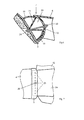
- the inventive supporting device has ( Fig. 1-3 ) designed as a hard plastic shell stiff
- Support framework with a support 1, which is formed as a substantially flat, slightly bent forwardly on the sides wall. He is at the in the FIGS. 1, 2 illustrated normal position of the support device, which it both when it is parked on the ground and when it is worn, assumes, oriented approximately vertically, with slight inclination forward.
- a hip support adjoins, consisting of two of its side edges parallel approximately horizontally projecting forward, integral with the carrier 1, about 20 cm long plate-shaped projections 2a, b.
- a bar 3 is attached at each of the extensions 2a, b.
- the strips 3 form a hip holder to which a padded hip belt 4 is fixed, the inside of which forms a contact surface. It has a lying between the strips 3 middle section, connect to the both sides with the same one-piece side sections, the ends of which are detachably connected by a Houtheasternsehnalle 5.
- a shoulder restraint 6 In the region of the upper end, a shoulder restraint 6, likewise integral therewith and approximately 20 cm long, sloping slightly upwards, adjoins the support 1, which is formed like a roof. With her a plate-shaped shoulder bracket 8 is connected via a ball joint 7. The latter is padded on the front, which forms a contact surface, and carries there on both sides of the ball joint 7 each have a shoulder strap assembly consisting of a padded upper flange 9 and a lower flange 10 and a buckle 11 which connects them. The lower chord 10 is attached to the buckle 11 so that the length of the portion thereof lying between the anchor at the shoulder support 8 and the buckle 11 is adjustable.
- the total length of the loop formed by the upper belt 9 and the said portion of the lower belt 10 is adjustable and can be adapted to the needs of the user. It is usually dimensioned so that it runs relatively just over the shoulder and under the armpits. It thereby gives the carrier a secure fit, which leaves her little freedom to uncontrolled movements. Because of the ball joint 7 but the mobility of the user is not significantly limited.
- the lower belt 10 is passed through the buckle 11 to the end of the extension 2a, b, at the upper side of which its end is anchored.
- the shoulder strap assembly is between the in Fig. 4 1, in which the portion lying between the buckle 11 and the extension 2a, b is stretched and the loop is wide and the in Fig. 5 shown second setting in which the loop is tight and the lying between the buckle 11 and the extension 2a, b section is loose, um plausible.
- the first setting is about cheaper when climbing with a snowboard attached to the support device, because the train to the rear of the shoulder is slightly reduced and the support frame is more closely fixed to the user. That the mobility of the back is more limited, hardly disturbs the rise.
- the second setting is better for the downhill, because the mobility of the back is hardly limited.
- the lower flange 10 is fixed to the buckle 11 so that it can not move by train alone, but only by engagement of the user. In both training, the two Shoulder strap assemblies are releasably connected by a front transverse chest strap.
- the carrier 1 has at the back in the region of the upper end and the lower end depending on a transverse fastening belt 14 and 15, respectively.
- the fastening straps 14, 15 can be used to larger items such as snowboard, ski, snowshoes, ski boots, helmet, a bag or container u.ä. fasten it to the support frame and secure it safely and essentially without play.
- Laterally attachment straps 16 are attached to the extensions 2a, b, to which other objects such as bottle holder, carabiner, camera, etc. can be attached so that they even without removal of the support device for the user are reachable.
- Another fastening strap 17 is attached to the top of the shoulder rest 6.
- 6 attachment straps can be provided laterally on the shoulder support. In this case, ski can be tied laterally.
- the ball joint 7 between the shoulder support 6 and the shoulder support 8 is in Fig. 6 shown.
- the shoulder support 6 has centrally a shell 18, which forms a concave, spherical cap-shaped outer articular surface.
- a head 19 is formed on the shoulder mount 8, which forms a corresponding hemispherical convex inner articular surface, which bears against the outer articular surface, but is somewhat larger, so that the head 19 can be rotated relative to the shell 18 over a limited solid angle.
- the inner joint surface on a circular recess 20, from the edges of a cone-shaped wall 21 emanates.
- the wall 21 breaks off below the tip of the cone, so that it has a lying approximately in the center of the inner joint surface hole, which is opposite to a hole in the middle of the shell 18.
- the voltage applied to the outside of the shell 18 stop 23 is slidably formed on the connecting part 22, for example as a nut with internal thread, which engages with a thread on the connecting part 22.
- the anchoring of the strips 3 of the hip support at the ends of the extensions 2a, b of the hip support is designed so that the height of the strips 3 is adjustable.
- the connection between the extension 2b and the corresponding bar is identical - a number at equal intervals with each other arranged holes 25 attached, while the corresponding bar 3 at mid-height also a Hole, with which one of the holes 25 covers.
- Through the holes protrudes a bolt 26 which is fixed by a nut. After removal of the bolt 26, the bar 3 can be moved, brought another of the holes 25 with the hole in the extension 2a to cover and the bolt 26 pushed through again and fixed. In this way, the distance of the waist belt 4 from the shoulder belt assemblies to the back length of the user can be adjusted.
- the carrier can be like a frame or the shoulder support formed like a bow.
- the bag is then, if no larger object is attached to the carrier, accessible from the rear or from above and he can, especially if it is very crowded, also projecting backwards or upwards over the carrier.
- the hip support and the shoulder support at least the contact surfaces coming to the user to the plant, with sufficient distance, usually about 10cm to 25cm, preferably 15cm to 20cm are arranged in front of the wearer, so that the user does not collide with the same and is not obstructed during movements.
- the hard shell construction may also be replaced by a framework of bars or hollow bars of metal.
- an elastic connection or u.U. be provided a linear joint.
- the hip support integral and articulated e.g. also a ball joint
- the shoulder mount should be rigidly connected to the shoulder rest, so that the position of the support frame is sufficiently established.
- the height adjustment of the hip belt can be structurally designed differently.
Landscapes
- Portable Outdoor Equipment (AREA)
- Purses, Travelling Bags, Baskets, Or Suitcases (AREA)
- Electrical Discharge Machining, Electrochemical Machining, And Combined Machining (AREA)
- Fluid-Damping Devices (AREA)
Abstract
Description
Die Erfindung betrifft eine rucksackartige Tragvorrichtung, wie sie z.B. bei Wanderungen, beim Radfahren und auf Schi-und Snowboardtouren verwendet werden.The invention relates to a backpack-type carrying device, such as e.g. can be used for hiking, cycling and on ski and snowboard tours.
Uebliche gattungsgemässe Tragvorrichtungen sind gewöhnlich als Rucksäcke aus festem textilen Material ausgebildet, an deren Vorderseite im Bereich des unteren Endes ein gepolsterter Hüftgurt angebracht ist, mit einem mit dem Sack vernähten Mittelabschnitt und über die Seitenränder des Sackes hinausragenden Seitenabschnitten, deren Enden durch eine Schnalle verbindbar sind, ausserdem z.B. zwei an den Rändern der Vorderseite gegen das obere Ende laufende feste Polsterstreifen, die die Tragvorrichtung etwas versteifen und deren Vorderseite vom Rücken des Benutzers beabständen, was Luftzirkulation ermöglicht und so die Entwicklung und Ansammlung von Schweiss verringert. Die Schultergurte schliessen oben an die Enden der Polsterstreifen an, während ihre unteren Enden z.B. unmittelbar seitlich des Sackes oben am Hüftgurt festgemacht sind.Common generic support devices are usually designed as backpacks made of solid textile material, at the front in the region of the lower end a padded hip belt is attached, with a sewn with the bag center portion and beyond the side edges of the bag protruding side portions whose ends are connected by a buckle , for example two fixed padding strips running at the edges of the front against the upper end, which slightly stiffen the carrying device and strip its front from the back of the user, allowing for air circulation and thus reducing the development and accumulation of sweat. The shoulder straps close at the top to the ends of the cushion strips, while their lower ends e.g. are fastened at the top of the hip belt on the side of the bag.
Derartige Tragvorrichtungen sind zum Tragen verhältnismässig grosser und schwerer Gegenstände, die nicht im Rucksack Platz finden, sondern an seiner Aussenseite, insbesondere Rückseite befestigt werden müssen wie z.B. Snowboards oder Schneeschuhe, Schi, Schischuhe oder Helme, wenig geeignet, da die besagten Gegenstände lediglich über den flexiblen Sack mit dem Hüftgurt und den Schultergurten verbunden sind und daher ihre Lage diesen fest am Benutzer anliegenden Teilen gegenüber nicht zuverlässig fixiert ist. Es kann daher leicht geschehen, dass sich der Gegenstand, z.B. ein Snowboard, verschiebt oder verdreht. Dadurch kann es zu einer Fehlbelastung des Rückens und in der Folge zu schmerzhaften Verspannungen kommen, ausserdem kann der Gegenstand mit Kopf oder Beinen des Benutzers kollidieren. Da ausserdem der Sack an der Rückseite zu öffnen ist, ist sein Inhalt schwer zugänglich, wenn dort ein Gegenstand der erwähnten Art befestigt ist. Oft muss derselbe entfernt werden, bevor der Sack geöffnet werden kann.Such carrying devices are for carrying relatively large and heavy objects that do not fit into the backpack, but must be attached to its outside, especially back such as snowboards or snowshoes, ski, ski boots or helmets, little suitable because the said objects only on the flexible Sack are connected to the waist belt and the shoulder straps and therefore their position is not fixed reliably against these parts firmly against the user. It can therefore easily happen that the object, eg a snowboard, shifts or twists. This can lead to an incorrect loading of the back and as a result to painful tension, in addition, the object can collide with the user's head or legs. In addition, since the bag is to be opened at the back, its content is difficult to access, if there is an object of the kind mentioned attached. Often, it must be removed before the bag can be opened.
Aehnliche Nachteile hat eine bekannte gattungsgemässe Tragvorrichtung (s.
Es sind auch kleinere Tragvorrichtungen vorgeschlagen worden, bei denen der Sack zum grösseren Teil durch eine Hartschale ersetzt und nur die Vorderseite flexibel ausgebildet ist (
Aus der
Der Erfindung liegt die Aufgabe zu Grunde, eine gattungsgemässe Tragvorrichtung dahingehend zu verbessern, dass sie sich auch zum Tragen grösserer, an der Aussenseite befestigter Gegenstände eignet.The invention is based on the object to improve a generic support device to the effect that it is also suitable for carrying larger, attached to the outside of objects.
Diese Aufgabe wird durch die Merkmale im Kennzeichen des Anspruchs 1 gelöst.This object is solved by the features in the characterizing part of
Die erfindungsgemässe Tragvorrichtung ermöglicht es, auch grössere Gegenstände wie Snowboards oder Schneeschuhe, Schi, Schischuhe, Helme u.ä. derart an der Aussenseite zu befestigen, dass ihre Lage gegenüber am Benutzer fixierten Teilen wie z.B. dem Hüftgurt im wesentlichen festgelegt ist. Kollisionen eines der besagten Gegenstände mit dem Körper des Benutzers und daraus resultierende Verletzungen oder Behinderungen sind damit weitgehend unterbunden.The inventive support device makes it possible, even larger items such as snowboards or snowshoes, ski, ski boots, helmets, etc. be attached to the outside so that its position relative to the user fixed parts such as the hip belt is essentially fixed. Collisions of one of said objects with the user's body and resulting injuries or disabilities are thus largely prevented.
Im folgenden wird die Erfindung anhand von Figuren, welche lediglich ein Ausführungsbeispiel darstellen, näher erläutert. Es zeigen
- Fig. 1
- eine erfindungsgemässe Tragvorrichtung von der Seite,
- Fig. 2
- die erfindungsgemässe Tragvorrichtung von hinten,
- Fig. 3
- die erfindungsgemässe Tragvorrichtung von vorn,
- Fig. 4
- eine hinsichtlich der Schultergurtanordnungen abgewandelte Ausbildung der erfindungsgemässen Tragvorrichtung mit einer ersten Einstellung der Schultergurtanordnungen,
- Fig. 5
- die Tragvorrichtung von
Fig. 4 mit einer zweiten Einstellung der Schultergurtanordnungen, - Fig. 6
- einen vergrösserten Schnitt durch einen Teil einer Schulterstütze der erfindungsgemässen Tragvorrichtung und
- Fig. 7
- einen vergrösserten Ausschnitt aus einer Seitenansicht der erfindungsgemässen Tragvorrichtung mit einer Hüfthalterung und einem Teil einer Hüftstütze.
- Fig. 1
- an inventive support device from the side,
- Fig. 2
- the inventive support device from behind,
- Fig. 3
- the inventive support device from the front,
- Fig. 4
- a modified embodiment of the inventive carrying device with respect to the shoulder strap arrangements with a first adjustment of the shoulder strap arrangements,
- Fig. 5
- the carrying device of
Fig. 4 with a second adjustment of the shoulder belt arrangements, - Fig. 6
- an enlarged section through a portion of a shoulder support of the inventive support device and
- Fig. 7
- an enlarged detail of a side view of the inventive support device with a hip support and a part of a hip support.
Die erfindungsgemässe Tragvorrichtung weist (
Traggerüst auf, mit einem Träger 1, der als im wesentlichen ebene, an den Seiten leicht nach vorn gebogene Wand ausgebildet ist. Er ist bei der in den
Im Bereich des unteren Endes des Trägers 1 schliesst eine Hüftstütze an, die aus zwei von seinen Seitenrändern parallel etwa waagrecht nach vorn ragenden, mit dem Träger 1 einstückigen, ca. 20 cm langen plattenförmigen Fortsätzen 2a,b besteht. An jedem der Fortsätze 2a,b ist eine Leiste 3 befestigt. Die Leisten 3 bilden eine Hüfthalterung, an welcher ein gepolsterter Hüftgurt 4 befestigt ist, dessen Innenseite eine Anlagefläche bildet. Er weist einen zwischen den Leisten 3 liegenden Mittelabschnitt auf, an den beidseits mit demselben einstückige Seitenabschnitte anschliessen, deren Enden durch eine Hüftsehnalle 5 lösbar verbunden sind.In the region of the lower end of the
Im Bereich des oberen Endes schliesst an den Träger 1 eine ebenfalls mit ihm einstückige, ca. 20 cm lange, leicht schräg nach oben geneigt nach vorn abragende Schulterstütze 6 an, die dachartig ausgebildet ist. Mit ihr ist über ein Kugelgelenk 7 eine plattenförmige Schulterhalterung 8 verbunden. Letztere ist an der Vorderseite, welche eine Anlagefläche bildet, gepolstert und trägt dort beidseits des Kugelgelenks 7 jeweils eine Schultergurtanordnung, bestehend aus einem gepolsterten Obergurt 9 und einem Untergurt 10 sowie einer Schnalle 11, welche sie verbindet. Der Untergurt 10 ist so an der Schnalle 11 befestigt, dass die Länge des zwischen der Verankerung an der Schulterhalterung 8 und der Schnalle 11 liegenden Abschnitts desselben verstellbar ist. Damit ist die Gesamtlänge der vom Obergurt 9 und dem besagten Abschnitt des Untergurts 10 gebildeten Schlaufe einstellbar und kann an die Bedürfnisse des Benutzers angepasst werden. Sie wird in der Regel so dimensioniert, dass sie verhältnismässig knapp über die Schulter und unter den Achseln durchläuft. Sie vermittelt dadurch der Tragvorrichtung einen sicheren Sitz, der ihr nur wenig Freiheit zu unkontrollierten Bewegungen lässt. Wegen des Kugelgelenks 7 ist aber die Beweglichkeit des Benutzers dadurch nicht wesentlich eingeschränkt.In the region of the upper end, a
Bei der in
Die erste Einstellung ist etwa beim Aufstieg mit einem an der Tragvorrichtung befestigten Snowboard günstiger, weil der Zug nach hinten an der Schulter etwas vermindert wird und das Traggerüst enger am Benutzer fixiert ist. Dass die Beweglichkeit des Rückens stärker eingeschränkt ist, stört beim Aufstieg kaum. Die zweite Einstellung ist für die Abfahrt besser geeignet, da die Beweglichkeit des Rückens kaum eingeschränkt ist. Der Untergurt 10 ist an der Schnalle 11 so festgelegt, dass er sich nicht durch Zug allein verschieben kann, sondern nur durch Eingriff des Benutzers. Bei beiden Ausbildungen können die beiden Schultergurtanordnungen durch einen vorn quer verlaufenden Brustgurt lösbar verbunden sein.The first setting is about cheaper when climbing with a snowboard attached to the support device, because the train to the rear of the shoulder is slightly reduced and the support frame is more closely fixed to the user. That the mobility of the back is more limited, hardly disturbs the rise. The second setting is better for the downhill, because the mobility of the back is hardly limited. The
Der Zwischenraum zwischen dem Träger 1 und den mit Abstand vor demselben angeordneten Halterungen, der Hüfthalterung und der Schulterhalterung 8, der vom Träger 1, den Fortsätzen 2a;b der Hüftstütze und der dachartigen Schulterstütze 6, die zusammen ein einstückiges schalenartiges Teil bilden, z.T. umschlossen wird, aber von vorn und den Seiten weitgehend frei zugänglich ist, wird z.T. von einem Sack 12 ausgefüllt, der z.B. mit Riemen, am Träger 1 befestigt ist, an dessen Vorderseite er anliegt und ausserdem auf eingebogenen Bodenpartien der Fortsätze 2a,b aufsitzt. Er ist so dimensioniert, dass er den besagten Zwischenraum nicht ganz ausfüllt, so dass er vom Rücken des Benutzers überall beabstandet ist. Er hat an der Vorderseite eine z.B. durch einen Reissverschluss verschliessbare Oeffnung 13, so dass sein Inhalt bei abgenommener Tragvorrichtung sofort zugänglich ist, unabhängig davon, ob an der Rückseite des Trägers 1 Gegenstände befestigt sind oder nicht. Er kann zudem von den Seiten zugängliche separate Taschen aufweisen.The space between the
Der Träger 1 weist an der Rückseite im Bereich des oberen Endes und des unteren Endes je einen querverlaufenden Befestigungsgurt 14 bzw. 15 auf. Die Befestigungsgurten 14, 15 können dazu verwendet werden, grössere Gegenstände wie Snowboard, Schi, Schneeschuhe, Schischuhe, Helm, einen Sack oder Behälter u.ä. am Traggerüst festzuschnallen und damit sicher und im wesentlichen spielfrei zu befestigen. Seitlich sind an den Fortsätzen 2a,b weitere Befestigungsriemen 16 angebracht, an denen weitere Gegenstände wie Flaschenhalter, Karabiner, Kamera usw. so angehängt werden können, dass sie auch ohne Abnahme der Tragvorrichtung für den Benutzer erreichbar sind. Ein weiterer Befestigungsriemen 17 ist oben an der Schulterstütze 6 angebracht. Zusätzlich können auch seitlich an der Schulterstütze 6 Befestigungsriemen vorgesehen werden. In diesem Fall können auch Schi seitlich aufgebunden werden.The
Das Kugelgelenk 7 zwischen der Schulterstütze 6 und der Schulterhalterung 8 ist in
Durch die beiden Löcher ist ein längliches Verbindungsteil 22, z.B. ein Drahtabschnitt oder vorzugsweise ein Stift, geführt, welcher jeweils an den Aussenseiten seitlich über die Löcher überstehende Anschläge 23, 24 aufweist, so dass das Verbindungsteil 22 das Kugelgelenk zusammenhält. Der an der Aussenseite der Schale 18 anliegende Anschlag 23 ist am Verbindungsteil 22 verschiebbar ausgebildet, z.B. als Mutter mit Innengewinde, das mit einem Gewinde am Verbindungsteil 22 eingreift. Durch Verschieben des Anschlags 23 kann der Anpressdruck zwischen der äusseren und der inneren Gelenkfläche eingestellt werden und damit der Widerstand, den das Kugelgelenk 7 Drehungen entgegensetzt. Der Anschlag 23 kann auch ganz entfernt werden, worauf die Schulterhalterung 8 abgenommen werden kann. Statt des Anschlags 23 kann natürlich auch der Anschlag 24 verstellbar und abnehmbar ausgebildet sein.An elongate connecting
Die Verankerung der Leisten 3 der Hüfthalterung an den Enden der Fortsätze 2a;b der Hüftstütze ist so ausgebildet, dass die Höhe der Leisten 3 verstellbar ist. Dazu ist längs des geraden, annähernd senkrechten Randes am Ende des Fortsatzes 2a - die Verbindung zwischen dem Fortsatz 2b und der entsprechenden Leiste ist gleich ausgebildet - eine Anzahl in gleichen Abständen untereinander angeordneter Löcher 25 angebracht, während die entsprechende Leiste 3 auf mittlerer Höhe ebenfalls ein Loch aufweist, mit dem sich eines der Löcher 25 deckt. Durch die Löcher ragt ein Bolzen 26, der durch eine Mutter fixiert ist. Nach Entfernen des Bolzens 26 kann die Leiste 3 verschoben, ein anderes der Löcher 25 mit dem Loch im Fortsatz 2a zur Deckung gebracht und der Bolzen 26 wieder durchgeschoben und fixiert werden. Auf diese Weise kann der Abstand des Hüftgurtes 4 von den Schultergurtanordnungen an die Rückenlänge des Benutzers angepasst werden.The anchoring of the
Es sind zahlreiche Abwandlungen des geschilderten Ausführungsbeispiels möglich, ohne dass das Gebiet der Erfindung verlassen würde. So kann z.B. der Träger rahmenartig durchbrochen oder die Schulterstütze bügelartig ausgebildet sein. Der Sack ist dann, wenn kein grösserer Gegenstand am Träger befestigt ist, auch von hinten bzw. von oben zugänglich und er kann, vor allem, wenn er sehr voll ist, auch nach hinten oder nach oben über den Träger hinausragen. Es ist auch möglich, Säcke verschiedener Grösse zum Auswechseln vorzusehen, bei rahmenartiger Ausbildung des Trägers etwa einen kleineren Sack für Tagestouren, der auf der Rückseite nicht über den Träger übersteht und damit die Befestigung eines grösseren Gegenstandes dort nicht behindert und einen grösseren für Mehrtagestouren, der auf der Rückseite übersteht. In letzterem Fall können u.U. nur an den Seiten des Trägers grössere Gegenstände befestigt werden. Es ist ausserdem möglich, mehrere Säcke und Taschen vorzusehen, die abwechselnd oder gleichzeitig am Träger befestigt sein können. Wesentlich ist, dass die Hüfthalterung und die Schulterhalterung, jedenfalls die am Benutzer zur Anlage kommenden Anlageflächen derselben, mit ausreichendem Abstand, in der Regel ca. 10cm bis 25cm, vorzugsweise 15cm bis 20cm vor dem Träger angeordnet sind, sodass der Benutzer nicht mit demselben kollidiert und bei Bewegungen nicht behindert wird.Numerous modifications of the described embodiment are possible without departing from the scope of the invention. Thus, for example, the carrier can be like a frame or the shoulder support formed like a bow. The bag is then, if no larger object is attached to the carrier, accessible from the rear or from above and he can, especially if it is very crowded, also projecting backwards or upwards over the carrier. It is also possible to provide bags of different size for replacement, with frame-like design of the Carrier about a smaller bag for day trips, which does not survive on the back of the carrier and thus does not hinder the attachment of a larger object there and a larger for multi-day tours, which survives on the back. In the latter case may be attached only on the sides of the carrier larger items. It is also possible to provide several bags and bags that can be alternately or simultaneously attached to the carrier. It is essential that the hip support and the shoulder support, at least the contact surfaces coming to the user to the plant, with sufficient distance, usually about 10cm to 25cm, preferably 15cm to 20cm are arranged in front of the wearer, so that the user does not collide with the same and is not obstructed during movements.
Die Hartschalenkonstruktion kann auch durch ein Gerüst aus Stäben oder Hohlstäben aus Metall ersetzt sein. Statt eines Kugelgelenks kann eine elastische Verbindung oder u.U. ein lineares Gelenk vorgesehen sein. Es ist auch, falls dies im Hinblick auf den im Vordergrund stehenden Einsatz und die mit ihm verbundenen Bewegungsarten günstiger erscheint, möglich, die Hüfthalterung einstückig auszubilden und über ein Gelenk, z.B. ebenfalls ein Kugelgelenk, an eine z.B. bügelförmig ausgebildete Hüftstütze zu koppeln. Dann sollte allerdings die Schulterhalterung starr mit der Schulterstütze verbunden sein, damit die Lage des Traggerüstes hinreichend festgelegt ist. Auch die Höhenverstellung des Hüftgurtes kann konstruktiv anders gestaltet sein.The hard shell construction may also be replaced by a framework of bars or hollow bars of metal. Instead of a ball joint, an elastic connection or u.U. be provided a linear joint. It is also possible, in view of the use in the foreground and the types of movement associated therewith, to make the hip support integral and articulated, e.g. also a ball joint, to a e.g. Pair bow-shaped hip support. Then, however, the shoulder mount should be rigidly connected to the shoulder rest, so that the position of the support frame is sufficiently established. The height adjustment of the hip belt can be structurally designed differently.
Claims (14)
zwei Schultergurtanordnungen,
einem steifem Traggerüst, mit einem Träger (1) sowie einer im Bereich des unteren Endes des Trägers (1) mit Abstand vor demselben angeordneten Hüfthalterung, an welcher der Hüftgurt (4) befestigt ist und,
einem im Bereich des oberen Endes des Trägers (1) ebenfalls im Abstand vor derselben angeordneten Schulterhalterung (8), an welcher die Schultergurtanordnungen mindestens einseitig befestigt sind, während der Sack (12) derart am Traggerüst befestigt ist, dass er mindestens teilweise vor dem Träger (1) liegt, aber nicht über die Hüfthalterung und die Schulterhalterung (8) hinausragt,
dadurch gekennzeichnet, dass
die Schultergurtanordnungen jeweils einen Obergurt (9) und einen Untergurt (10) umfassen, welche an der Schulterhalterung (8) verankert sind und eine Schlaufe ausbilden.Carrying device with a bag (12) for receiving cargo, with a hip belt (4),
two shoulder strap arrangements,
a rigid support frame, comprising a support (1) and a hip support arranged at a distance from the same in the region of the lower end of the support (1), to which the hip belt (4) is attached, and
a in the region of the upper end of the carrier (1) also at a distance from the same arranged shoulder support (8) to which the Schultergurtanordnungen are at least attached on one side, while the bag (12) is fixed to the support frame, that he at least partially in front of the carrier (1) lies, but does not protrude beyond the hip support and the shoulder support (8),
characterized in that
the shoulder belt assemblies each comprise a top flange (9) and a bottom flange (10) which are anchored to the shoulder support (8) and form a loop.
Applications Claiming Priority (2)
| Application Number | Priority Date | Filing Date | Title |
|---|---|---|---|
| CH01049/04A CH696922A5 (en) | 2004-06-22 | 2004-06-22 | Carrying device. |
| EP05750582A EP1758482B1 (en) | 2004-06-22 | 2005-06-22 | Carrying device |
Related Parent Applications (2)
| Application Number | Title | Priority Date | Filing Date |
|---|---|---|---|
| EP05750582A Division EP1758482B1 (en) | 2004-06-22 | 2005-06-22 | Carrying device |
| EP05750582.8 Division | 2005-06-22 |
Publications (2)
| Publication Number | Publication Date |
|---|---|
| EP2279679A2 true EP2279679A2 (en) | 2011-02-02 |
| EP2279679A3 EP2279679A3 (en) | 2014-10-01 |
Family
ID=34970082
Family Applications (2)
| Application Number | Title | Priority Date | Filing Date |
|---|---|---|---|
| EP10178374.4A Withdrawn EP2279679A3 (en) | 2004-06-22 | 2005-06-22 | Carrying device |
| EP05750582A Expired - Lifetime EP1758482B1 (en) | 2004-06-22 | 2005-06-22 | Carrying device |
Family Applications After (1)
| Application Number | Title | Priority Date | Filing Date |
|---|---|---|---|
| EP05750582A Expired - Lifetime EP1758482B1 (en) | 2004-06-22 | 2005-06-22 | Carrying device |
Country Status (9)
| Country | Link |
|---|---|
| US (1) | US20080203129A1 (en) |
| EP (2) | EP2279679A3 (en) |
| JP (1) | JP4724712B2 (en) |
| KR (1) | KR100865570B1 (en) |
| CN (1) | CN100528032C (en) |
| AT (1) | ATE492183T1 (en) |
| CH (1) | CH696922A5 (en) |
| DE (1) | DE502005010717D1 (en) |
| WO (1) | WO2005122824A2 (en) |
Families Citing this family (8)
| Publication number | Priority date | Publication date | Assignee | Title |
|---|---|---|---|---|
| ES1066384Y (en) * | 2007-08-30 | 2008-04-16 | Miguel Garcia Alfredo San | FRONT BACKPACK |
| US8714424B2 (en) * | 2009-03-24 | 2014-05-06 | Black Diamond Equipment Ltd. | Carrying device waist belt system |
| US9254030B2 (en) | 2009-03-24 | 2016-02-09 | Black Diamond Equipment, Ltd. | Carrying device dual shoulder strap system |
| WO2011053961A2 (en) | 2009-11-02 | 2011-05-05 | C & P Hiam Associates Llc | Stable backpack |
| US10617195B2 (en) * | 2013-07-19 | 2020-04-14 | Jeremy Nathan Coleman | Articulating backpack frame |
| JP7177652B2 (en) * | 2018-10-11 | 2022-11-24 | 株式会社マキタ | backpack equipment |
| CN109793339A (en) * | 2019-02-15 | 2019-05-24 | 杨钻星 | A kind of composite type Waistband structure based on outdoor sports |
| CN114041665B (en) * | 2021-11-08 | 2023-03-24 | 深圳市泰和联安防电子有限公司 | Wearable emergency command terminal |
Citations (4)
| Publication number | Priority date | Publication date | Assignee | Title |
|---|---|---|---|---|
| US5184873A (en) | 1990-08-16 | 1993-02-09 | Gewerkschaft Eisenhutte Westfalia Gmbh | Guides for mineral winning machines |
| US6179188B1 (en) | 1996-08-14 | 2001-01-30 | Dana Design, Ltd. | External frame backpack with flexible harness |
| US6179186B1 (en) | 1997-01-06 | 2001-01-30 | Global Act Ab | Backpack |
| WO2001097651A1 (en) | 2000-06-22 | 2001-12-27 | Global Act Aktiebolag | Backpack |
Family Cites Families (15)
| Publication number | Priority date | Publication date | Assignee | Title |
|---|---|---|---|---|
| BE433679A (en) * | 1938-04-22 | |||
| US2500784A (en) * | 1948-12-30 | 1950-03-14 | Jr James W Anderson | Rearview mirror |
| US3355075A (en) * | 1966-07-25 | 1967-11-28 | William H Dean | Pack frame |
| US4099657A (en) * | 1976-05-26 | 1978-07-11 | Zufich Anthony C | Backpack and frame apparatus |
| US4303186A (en) * | 1980-08-11 | 1981-12-01 | Ollinger Iv Charles G | Triaxially pivotable backpack carrier |
| GB8518106D0 (en) * | 1985-07-18 | 1985-08-21 | Clark D F | Back-packs |
| US5954253A (en) * | 1996-06-26 | 1999-09-21 | Johnson Worldwide Associates, Inc. | Flexible frame load carrying system |
| KR0183519B1 (en) * | 1996-11-09 | 1999-05-01 | 심수봉 | Control method of wearing close to the backpack and its device |
| GB9717300D0 (en) * | 1997-08-14 | 1997-10-22 | Berghaus Ltd | Improved rucksack |
| GB2343618A (en) * | 1998-11-14 | 2000-05-17 | David Foster | Bag |
| US6199732B1 (en) * | 1999-05-07 | 2001-03-13 | Johnson Outdoors Inc. | Load support system |
| FR2814349B1 (en) * | 2000-09-27 | 2002-12-06 | Salomon Sa | BACKPACK |
| FR2814350B1 (en) * | 2000-09-27 | 2003-07-04 | Salomon Sa | ATTACHMENT ELEMENT FOR CARRYING BAG |
| US6886727B2 (en) * | 2001-04-07 | 2005-05-03 | Talons Adventure Gear, Inc. | Detachable back pack waist belt |
| US7537143B1 (en) * | 2003-10-09 | 2009-05-26 | Nike, Inc. | Backpack with external frame |
-
2004
- 2004-06-22 CH CH01049/04A patent/CH696922A5/en not_active IP Right Cessation
-
2005
- 2005-06-22 CN CNB2005800203363A patent/CN100528032C/en not_active Expired - Fee Related
- 2005-06-22 KR KR1020067026969A patent/KR100865570B1/en not_active Expired - Fee Related
- 2005-06-22 EP EP10178374.4A patent/EP2279679A3/en not_active Withdrawn
- 2005-06-22 WO PCT/CH2005/000350 patent/WO2005122824A2/en not_active Ceased
- 2005-06-22 JP JP2007516938A patent/JP4724712B2/en not_active Expired - Fee Related
- 2005-06-22 DE DE502005010717T patent/DE502005010717D1/en not_active Expired - Lifetime
- 2005-06-22 AT AT05750582T patent/ATE492183T1/en active
- 2005-06-22 US US11/630,213 patent/US20080203129A1/en not_active Abandoned
- 2005-06-22 EP EP05750582A patent/EP1758482B1/en not_active Expired - Lifetime
Patent Citations (4)
| Publication number | Priority date | Publication date | Assignee | Title |
|---|---|---|---|---|
| US5184873A (en) | 1990-08-16 | 1993-02-09 | Gewerkschaft Eisenhutte Westfalia Gmbh | Guides for mineral winning machines |
| US6179188B1 (en) | 1996-08-14 | 2001-01-30 | Dana Design, Ltd. | External frame backpack with flexible harness |
| US6179186B1 (en) | 1997-01-06 | 2001-01-30 | Global Act Ab | Backpack |
| WO2001097651A1 (en) | 2000-06-22 | 2001-12-27 | Global Act Aktiebolag | Backpack |
Also Published As
| Publication number | Publication date |
|---|---|
| WO2005122824A3 (en) | 2006-06-29 |
| EP1758482B1 (en) | 2010-12-22 |
| CH696922A5 (en) | 2008-02-15 |
| ATE492183T1 (en) | 2011-01-15 |
| JP4724712B2 (en) | 2011-07-13 |
| EP1758482A2 (en) | 2007-03-07 |
| WO2005122824A2 (en) | 2005-12-29 |
| CN100528032C (en) | 2009-08-19 |
| DE502005010717D1 (en) | 2011-02-03 |
| JP2008503282A (en) | 2008-02-07 |
| EP2279679A3 (en) | 2014-10-01 |
| US20080203129A1 (en) | 2008-08-28 |
| KR20070051786A (en) | 2007-05-18 |
| CN1968620A (en) | 2007-05-23 |
| KR100865570B1 (en) | 2008-10-28 |
Similar Documents
| Publication | Publication Date | Title |
|---|---|---|
| DE69129353T2 (en) | Waist bag | |
| EP0542739B1 (en) | Knapsack | |
| DE69218926T2 (en) | backpack | |
| EP4316309A1 (en) | Supporting frame | |
| DE69913481T2 (en) | HAMMOCK | |
| DE102017112759B4 (en) | backpack | |
| EP4324357A1 (en) | Support system for an item of equipment | |
| EP1758482B1 (en) | Carrying device | |
| DE29615828U1 (en) | backpack | |
| DE102006048185A1 (en) | Backpack with side sliding module | |
| EP2684486B1 (en) | Backpack with additional attachment and padding | |
| DE8809469U1 (en) | Carrying bag, especially photo ready bag | |
| DE102018219963B4 (en) | BACKPACK | |
| DE69209806T2 (en) | backpack | |
| AT371677B (en) | BACKPACK | |
| DE202017102930U1 (en) | A multifunctional bicycle bag | |
| EP1139004A2 (en) | Transport housing to be mounted to a supporting device and fastening belt for such an housing | |
| DE8909738U1 (en) | Hand towel | |
| DE19638502A1 (en) | Rucksack with flexible support belt | |
| EP0284767A2 (en) | Rucksack | |
| EP3217834B1 (en) | Backpack | |
| DE60038060T2 (en) | Improved backpack system | |
| DE9101486U1 (en) | Backpack | |
| DE29506601U1 (en) | backpack | |
| DE20311431U1 (en) | carrying device |
Legal Events
| Date | Code | Title | Description |
|---|---|---|---|
| PUAI | Public reference made under article 153(3) epc to a published international application that has entered the european phase |
Free format text: ORIGINAL CODE: 0009012 |
|
| AC | Divisional application: reference to earlier application |
Ref document number: 1758482 Country of ref document: EP Kind code of ref document: P |
|
| AK | Designated contracting states |
Kind code of ref document: A2 Designated state(s): AT BE BG CH CY CZ DE DK EE ES FI FR GB GR HU IE IS IT LI LT LU MC NL PL PT RO SE SI SK TR |
|
| RAP1 | Party data changed (applicant data changed or rights of an application transferred) |
Owner name: FLINK GMBH |
|
| RAP1 | Party data changed (applicant data changed or rights of an application transferred) |
Owner name: FLINK GMBH |
|
| PUAL | Search report despatched |
Free format text: ORIGINAL CODE: 0009013 |
|
| AK | Designated contracting states |
Kind code of ref document: A3 Designated state(s): AT BE BG CH CY CZ DE DK EE ES FI FR GB GR HU IE IS IT LI LT LU MC NL PL PT RO SE SI SK TR |
|
| RIC1 | Information provided on ipc code assigned before grant |
Ipc: A45F 3/04 20060101AFI20140826BHEP |
|
| STAA | Information on the status of an ep patent application or granted ep patent |
Free format text: STATUS: THE APPLICATION IS DEEMED TO BE WITHDRAWN |
|
| 18D | Application deemed to be withdrawn |
Effective date: 20150402 |