EP2279794A1 - Atomiseur électrostatique - Google Patents
Atomiseur électrostatique Download PDFInfo
- Publication number
- EP2279794A1 EP2279794A1 EP10007812A EP10007812A EP2279794A1 EP 2279794 A1 EP2279794 A1 EP 2279794A1 EP 10007812 A EP10007812 A EP 10007812A EP 10007812 A EP10007812 A EP 10007812A EP 2279794 A1 EP2279794 A1 EP 2279794A1
- Authority
- EP
- European Patent Office
- Prior art keywords
- electrode
- discharge
- discharge electrode
- opposite electrode
- atomization chamber
- Prior art date
- Legal status (The legal status is an assumption and is not a legal conclusion. Google has not performed a legal analysis and makes no representation as to the accuracy of the status listed.)
- Withdrawn
Links
- 238000000889 atomisation Methods 0.000 claims abstract description 43
- XLYOFNOQVPJJNP-UHFFFAOYSA-N water Substances O XLYOFNOQVPJJNP-UHFFFAOYSA-N 0.000 claims abstract description 35
- 238000009413 insulation Methods 0.000 claims description 18
- 239000003570 air Substances 0.000 description 21
- 230000005684 electric field Effects 0.000 description 4
- 238000007789 sealing Methods 0.000 description 4
- 238000010521 absorption reaction Methods 0.000 description 3
- 238000001816 cooling Methods 0.000 description 3
- 238000005192 partition Methods 0.000 description 3
- 238000004891 communication Methods 0.000 description 2
- 239000012141 concentrate Substances 0.000 description 2
- 230000000694 effects Effects 0.000 description 2
- 230000002093 peripheral effect Effects 0.000 description 2
- 230000001902 propagating effect Effects 0.000 description 2
- 239000012080 ambient air Substances 0.000 description 1
- 238000013461 design Methods 0.000 description 1
- 238000007599 discharging Methods 0.000 description 1
- 230000004992 fission Effects 0.000 description 1
- 239000011810 insulating material Substances 0.000 description 1
- 238000004519 manufacturing process Methods 0.000 description 1
- 238000000034 method Methods 0.000 description 1
- 238000012986 modification Methods 0.000 description 1
- 230000004048 modification Effects 0.000 description 1
- 238000012546 transfer Methods 0.000 description 1
Images


Classifications
-
- B—PERFORMING OPERATIONS; TRANSPORTING
- B05—SPRAYING OR ATOMISING IN GENERAL; APPLYING FLUENT MATERIALS TO SURFACES, IN GENERAL
- B05B—SPRAYING APPARATUS; ATOMISING APPARATUS; NOZZLES
- B05B5/00—Electrostatic spraying apparatus; Spraying apparatus with means for charging the spray electrically; Apparatus for spraying liquids or other fluent materials by other electric means
- B05B5/025—Discharge apparatus, e.g. electrostatic spray guns
- B05B5/0255—Discharge apparatus, e.g. electrostatic spray guns spraying and depositing by electrostatic forces only
-
- B—PERFORMING OPERATIONS; TRANSPORTING
- B05—SPRAYING OR ATOMISING IN GENERAL; APPLYING FLUENT MATERIALS TO SURFACES, IN GENERAL
- B05B—SPRAYING APPARATUS; ATOMISING APPARATUS; NOZZLES
- B05B5/00—Electrostatic spraying apparatus; Spraying apparatus with means for charging the spray electrically; Apparatus for spraying liquids or other fluent materials by other electric means
- B05B5/025—Discharge apparatus, e.g. electrostatic spray guns
- B05B5/053—Arrangements for supplying power, e.g. charging power
- B05B5/0533—Electrodes specially adapted therefor; Arrangements of electrodes
-
- B—PERFORMING OPERATIONS; TRANSPORTING
- B05—SPRAYING OR ATOMISING IN GENERAL; APPLYING FLUENT MATERIALS TO SURFACES, IN GENERAL
- B05B—SPRAYING APPARATUS; ATOMISING APPARATUS; NOZZLES
- B05B5/00—Electrostatic spraying apparatus; Spraying apparatus with means for charging the spray electrically; Apparatus for spraying liquids or other fluent materials by other electric means
- B05B5/025—Discharge apparatus, e.g. electrostatic spray guns
- B05B5/057—Arrangements for discharging liquids or other fluent material without using a gun or nozzle
-
- B—PERFORMING OPERATIONS; TRANSPORTING
- B05—SPRAYING OR ATOMISING IN GENERAL; APPLYING FLUENT MATERIALS TO SURFACES, IN GENERAL
- B05B—SPRAYING APPARATUS; ATOMISING APPARATUS; NOZZLES
- B05B7/00—Spraying apparatus for discharge of liquids or other fluent materials from two or more sources, e.g. of liquid and air, of powder and gas
- B05B7/0012—Apparatus for achieving spraying before discharge from the apparatus
Definitions
- the present invention relates to an electrostatic atomizer and, more particularly, a technique of reducing the discharge sound emitted frontwards.
- Japanese Patent Application Publication No. 2007-144425 discloses one example of the electrostatic atomizers which includes a discharge electrode, an opposite electrode positioned in a spaced-apart relationship with the discharge electrode and a water supply unit for supplying water for atomization to the discharge electrode.
- the electrostatic atomizer if a voltage is applied to the discharge electrode, the water adhering to the discharge electrode is subjected to electrostatic atomization, consequently generating charged water particulates which are discharged frontwards.
- frontwards denotes the side at which the opposite electrode is positioned in an opposing relationship with the discharge electrode.
- the electrostatic atomizer of the aforementioned configuration suffers from a problem in that the discharge sound generated from the discharge electrode is emitted frontwards, thus becoming a operation noise. This is because the discharge sound is likely to be amplified in an atomization chamber defined between the discharge electrode and the opposite electrode.
- a sound absorption device for absorbing the discharge sound emitted frontwards is additionally provided to prevent generation of noises.
- a problem is posed in that the provision of the sound absorption device leads to an increase in the overall device size and in the production cost.
- the present invention provides a small-sized cost-effective electrostatic atomizer capable of reducing the discharge sound emitted frontwards.
- an electrostatic atomizer including: a discharge electrode; an opposite electrode positioned in front of the discharge electrode in a spaced-apart relationship therewith; a housing for defining an atomization chamber between the discharge electrode and the opposite electrode; a water supply unit for supplying water for atomization to the discharge electrode; and a voltage application unit for applying a voltage to the discharge electrode, wherein the housing is provided with an air vent window through which the atomization chamber is opened laterally outwards, and wherein the opposite electrode is provided with a soundproof shield portion extended therefrom to cover, when seen from a front side of the opposite electrode, the space existing laterally outwards of the air vent window of the housing, the soundproof shield portion reflecting rearwards a discharge sound generated in the atomization chamber.
- the soundproof shield portion With this configuration, it is possible for the soundproof shield portion to reflect rearwards the discharge sound emitted laterally outwards through the air vent window, although the discharge sound is generated from the discharge electrode within the atomization chamber and then echo-amplified within the atomization chamber. In other words, the soundproof shield portion restrains the amplified discharge sound from propagating toward the front side (namely, the side where there exists a space to which the charged water particulates are discharged). Moreover, there is no need to additionally provide a sound absorption device or the like. This eliminates the possibility of incurring an increase in the overall size of the atomizer and in the cost.
- the voltage application unit may include a lead line leading to the discharge electrode, and the housing is provided with an insulation plate positioned between the lead line and the opposite electrode, the insulation plate including a reflector wall for reflecting the discharge sound generated in the atomization chamber toward the air vent window.
- the discharge sound amplified within the atomization chamber is reflected toward the air vent window by the reflector wall of the insulation plate and then reflected rearwards by the soundproof shield portion extending laterally outwards away from the air vent window. This helps restrain the amplified discharge sound from being discharged to the front side. Since the insulation plate is interposed between the lead line and the opposite electrode, the overall height of the atomizer can be reduced by bringing the opposite electrode into proximity to the lead line.
- the opposite electrode may include a dome-shaped body portion disposed around a tip of the discharge electrode and a tubular electrode portion extending toward the front side from the dome-shaped body portion.
- the housing is provided with an air vent window through which the atomization chamber is opened laterally outwards.
- the opposite electrode includes a soundproof shield portion for, when seen from the front side, covering the space existing laterally outwards of the air vent window of the housing.
- the soundproof shield portion is designed to reflect rearwards the discharge sound generated within the atomization chamber. This provides an advantageous effect in that it is possible to reduce the noise emitted to the front side and to avoid an increase in the overall size of the atomizer and in the cost.
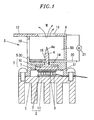
- FIG. 1 there is shown an electrostatic atomizer in accordance with a first embodiment of the present invention.
- the electrostatic atomizer of the present embodiment makes use of a Peltier unit 1 including a radiator part 3 and a cooler part 2.
- a discharge electrode 4 is connected to the cooler part 2 of the Peltier unit 1 so that the cooler part 2 can cool the discharge electrode 4.
- a support frame 5 is connected to the Peltier unit 1 to support an opposite electrode 6 at the tip end thereof, whereby the discharge electrode 4 and the opposite electrode 6 are fixed in a spaced-apart opposing relationship with each other.
- the support frame 5 makes up a housing 8 of the electrostatic atomizer.
- the Peltier unit 1 is of the type in which thermoelectric elements 9 are interposed between a pair of Peltier circuit plates 7. Heat is transferred from one of the Peltier circuit plates 7 to the other by supplying an electric current to the thermoelectric elements 9 electrically connected to one another.
- a cooling plate 10 is connected to the Peltier circuit plate 7 arranged at the upper side in Fig. 1 .
- the upper one of the Peltier circuit plates 7 and the cooling plate 10 make up the cooler part 2.
- a fin-shaped radiator body 11 is connected and fixed to the Peltier circuit plate 7 arranged at the lower side in Fig. 1 .
- the lower one of the Peltier circuit plates 7 and the radiator body 11 makes up the radiator part 3.
- the support frame 5 is made of an insulating material and formed into a tubular shape. One axial end of the support frame 5 is connected to the radiator body 11 of the Peltier unit 1 while the opposite electrode 6 is supported by and connected to the other axial end of the support frame 5.
- a partition wall 14 for bisecting the internal space of the support frame 5 into an atomization chamber 50 and a sealing chamber 51 is installed on the inner circumferential surface of the support frame 5.
- a communication hole 15 through which the atomization chamber 50 communicates with the sealing chamber 51 is provided at the center of the partition wall 14.
- the discharge electrode 4 is formed into a circular column shape and has a discharging tip portion 4a.
- the discharge electrode 4 is fitted through the communication hole 15 while positioning the tip portion 4a within the atomization chamber 50 and bringing the base end into contact with the cooler part 2 of the Peltier unit 1 within the sealing chamber 51.
- An air vent window 19 is provided in a portion of the side circumferential wall of the support frame 5 defining the atomization chamber 50.
- the opposite electrode 6 has a discharge hole 13.
- the atomization chamber 50 communicates with the external space through the air vent window 19 and the discharge hole 13 of the opposite electrode 6.
- a voltage-applying lead line 20 is connected at one end to the discharge electrode 4 within the support frame 5 and at the other end to a voltage application unit 21 arranged outside the support frame 5.
- the voltage application unit 21 applies a high voltage for electrostatic atomization between the discharge electrode 4 and the opposite electrode 6.
- a soundproof shield portion 12 extends laterally outwards from the outer circumferential portion of the opposite electrode 6.
- the soundproof shield portion 12 aims at reflecting the discharge sound generated within the atomization chamber 50.
- the soundproof shield portion 12 is arranged to hide a whole space S existing outside the air vent window 19 of the support frame 5 in a casing 60 (see Fig. 4 ) (hereinafter referred to as "out-of-window space S") when seen from the front side (i.e., when seen in a direction from the opposite electrode 6 towards the discharge electrode 4).
- the soundproof shield portion 12 is provided to hide the entirety of the out-of-window space S in the present embodiment, the present invention is not limited thereto. In other words, the out-of-window space S may not be fully covered with the soundproof shield portion 12.
- the soundproof shield portion 12 may be provided to cover most of the out-of-window space S or only the area of the out-of-window space S making great contribution to emitting sound in a direction that the charged water particulates are discharged.
- the discharge electrode 4 is cooled through the cooler part 2 due to the heat transfer within the thermoelectric elements 9.
- the cooler part 2 of the Peltier unit 1 for cooling the discharge electrode 4 serves as a water supply unit for supplying water for atomization to the discharge electrode 4.
- the voltage application unit 21 applies a high voltage to the discharge electrode 4 holding water in the tip portion 4a thereof so that electric charges can concentrate on the tip portion 4a of the discharge electrode 4 as a negative electrode, the water held at the tip portion 4a is repeatedly subjected to Rayleigh fission by a great deal of energy. This generates a large quantity of charged water particulates M having a diameter of nanometer size.
- the charged water particulates M are moved toward the opposite electrode 6 and then discharged frontwards through the discharge hole 13 of the opposite electrode 6.
- a fresh ambient air is introduced through the air vent window 19 into the space around the discharge electrode 4 within the atomization chamber 50, which assures stable supply of the moisture used in generating the charged water particulates M.
- the charged water particulates M are vigorously discharged to the outside because they come into the stream of the air introduced into the support frame 5 from the air vent window 19 and discharged from the discharge hole 13.
- a discharge sound is generated from the tip portion 4a of the discharge electrode 4 within the atomization chamber 50.
- the discharge sound is echoed and eventually amplified within the atomization chamber 50.
- the opposite electrode 6 positioned at the front side of the atomization chamber 50 is provided with the soundproof shield portion 12 extending laterally outwards. This ensures that the discharge sound emitted laterally outwards through the air vent window 19 is reflected rearwards by the soundproof shield portion 12.
- Presence of the soundproof shield portion 12 restrains the amplified discharge sound from propagating frontwards (i.e., toward the side where there exists a space to which the charged water particulates M are discharged). This makes it possible to solve the problem of generating operation noise. Since the generation of operation noise can be suppressed by merely extending the soundproof shield portion 12 from the opposite electrode 6, the electrostatic atomizer can be prevented from becoming large-sized and costly.
- the opposite electrode 6 includes a dome-shaped body portion 30 protruding frontwards to surround the discharge hole 13 of the opposite electrode 6.
- the body portion 30 is formed to ensure that the distance d between the inner surface thereof and the tip portion 4a of the discharge electrode 4 becomes uniform.
- strong electric fields are generated in the extensive three-dimensional range between the body portion 30 of the opposite electrode 6 and the tip portion 4a of the discharge electrode 4.
- the degree of concentration of the electric fields on the tip portion 4a of the discharge electrode 4 grows very high. This makes it possible to efficiently concentrate electric charges on the water held by the discharge electrode 4, thereby generating charged water particulates M.
- the shape of the body portion 30 of the opposite electrode 6 is not limited to the dome shape shown in Figs. 2A and 2B . It will be all right if at least a portion of the inner surface of the body portion 30 surrounding the tip portion 4a of the discharge electrode 4 has a cross-sectional shape that conforms to the arc line described about the tip portion 4a of the discharge electrode 4 with a radius equal to the shortest distance d between the tip portion 4a of the discharge electrode 4 and the opposite electrode 6.
- a tubular electrode portion 31 is formed at the peripheral edge of the discharge hole 13 of the body portion 30 to extend frontwards (i.e., away from the discharge electrode 4).
- electric fields are also generated between the inner circumferential surface of the tubular electrode portion 31 and the tip portion 4a of the discharge electrode 4. This makes it possible to further increase the degree of concentration of the electric fields on the tip portion 4a of the discharge electrode 4.
- the charged water particulates M generated in a large quantity are introduced into the discharge hole 13 and attracted to the inner circumferential surface of the tubular electrode portion 31 and then discharged through the tubular electrode portion 31.
- the opposite electrode 6 is supported by and fixed to the tip portions of a plurality of (four, in the illustrated example) support posts 32 upstanding from the support frame 5.
- the atomization chamber 50 is defined between the support posts 32 and the partition wall 14 of the support frame 5 and the opposite electrode 6.
- the lateral sides of the atomization chamber 50 are all opened to the outside except the portions where the support posts 32 exist. In other words, the open portions between the adjoining support posts 32 serve as air vent windows 19 through which the atomization chamber 50 is opened laterally outwards.
- a soundproof shield portion 12 is formed in the outer periphery of the ring-shaped opposite electrode 6 to extend along the entire perimeter thereof. When seen from the front side, the entirety of the out-of-window space S is hidden by the soundproof shield portion 12.
- the charged water particulates M can be efficiently generated by the dome-shaped body portion 30 of the opposite electrode 6 but the discharge sound generated within the atomization chamber 50 is likely to be amplified due to the curvature of the body portion 30.
- the discharge sound thus amplified is reflected rearwards by the soundproof shield portion 12 of the opposite electrode 6 and consequently restrained from being discharged frontwards as a noise.
- the efficiency of generating the charged water particulates M is improved by the dome-shaped body portion 30 and the tubular electrode portion 31, which makes it possible to generate a sufficiently large quantity of charged water particulates M even with a small-sized atomizer.
- a soundproof unit can be provided by merely extending the soundproof shield portion 12 from the opposite electrode 6. This eliminates the possibility that the size of the electrostatic atomizer is unnecessarily increased. With the electrostatic atomizer of the present embodiment, therefore, it is possible to reduce the noise while securing a required quantity of charged water particulates M. Moreover, it becomes possible to achieve a reduction in the overall size of the electrostatic atomizer and in the cost.
- Fig. 3 is a side view showing the electrostatic atomizer of the third embodiment.
- Fig. 4 is a section view of the electrostatic atomizer taken along line IV-IV in Fig. 3 .
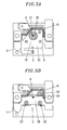
- Fig. 5A is a front view of the electrostatic atomizer of the third embodiment with the opposite electrode attached thereto and Fig. 5B is a front view thereof with the opposite electrode removed for clarity.
- the opposite electrode 6 of the present embodiment is supported by and fixed to the end portions of three support posts 32 upstanding from the support frame 5.
- An insulation plate 41 is fixed to the support frame 5 so that it can be positioned between the lead line 20, through which to apply a voltage to the discharge electrode 4, and the opposite electrode 6 (see Fig. 4 ).
- the insulation plate 41 is provided with a through hole 42 through which the discharge electrode 4 passes.
- a reflector wall 43 for reflecting the discharge sound generated from the tip portion 4a of the discharge electrode 4 toward air vent windows 19 is formed near the through hole 42 of the insulation plate 41.
- the reflector wall 43 is inclined laterally outwards so that it can come closer to the opposite electrode 6 as it goes away from the discharge electrode 4.
- the support frame 5 and the insulation plate 41 fixed thereto make up a housing 8.
- An atomization chamber 50 in which the tip portion 4a of the discharge electrode 4 lies is formed between the housing 8 and the opposite electrode 6.
- the lateral sides of the atomization chamber 50 are opened to the outside except the portions where the support posts 32 exist and the portion where the reflector wall 43 of the insulation plate 41 exists.
- the open portions between the adjoining support posts 32 and the portion where the reflector wall 43 of the insulation plate 41 does not exist serve as air vent windows 19 through which the atomization chamber 50 is opened laterally outwards.
- a soundproof shield portion 12 is provided in the outer peripheral portion of the opposite electrode 6 to extend away from the reflector wall 43 of the insulation plate 41. This ensures that the area of the out-of-window space S making greater contribution to emitting sound (i.e., the opposite side of the discharge electrode 4 to the reflector wall 43 of the insulation plate 41) in a direction that the charged water particulates are discharged is hidden by the soundproof shield portion 12 when seen from the front side.
- the charged water particulates M can be efficiently generated by the dome-shaped body portion 30 and the tubular electrode portion 31 of the opposite electrode 6 but the discharge sound generated within the atomization chamber 50 is likely to be amplified due to the curvature of the body portion 30.
- the discharge sound thus amplified is reflected toward the air vent windows 19 by the reflector wall 43 of the insulation plate 41 and then reflected rearwards by the soundproof shield portion 12 extending away from the air vent windows 19. This helps restrain the discharge sound from being released frontwards.
- the efficiency of generating the charged water particulates M is improved by the dome-shaped body portion 30 and the tubular electrode portion 3, which makes it possible to generate a sufficiently large quantity of charged water particulates M even with a small-sized atomizer.
- a soundproof unit can be provided by merely extending the soundproof shield portion 12 from the opposite electrode 6. This eliminates the possibility that the size of the electrostatic atomizer is unnecessarily increased.
- insulation plate 41 is interposed between the lead line 20 leading to the discharge electrode 4 and the opposite electrode 6, insulation can be secured even when the overall height of the atomizer is reduced by bringing the opposite electrode 6 into proximity to the lead line 20. This helps further reduce the size of the electrostatic atomizer.
- the electrostatic atomizer of the present embodiment therefore, it is possible to reduce the noise while securing a required quantity of charged water particulates M. Moreover, it becomes possible to achieve a reduction in the overall size of the electrostatic atomizer and in the cost.
Landscapes
- Electrostatic Spraying Apparatus (AREA)
Applications Claiming Priority (1)
| Application Number | Priority Date | Filing Date | Title |
|---|---|---|---|
| JP2009175905A JP2011025204A (ja) | 2009-07-28 | 2009-07-28 | 静電霧化装置 |
Publications (1)
| Publication Number | Publication Date |
|---|---|
| EP2279794A1 true EP2279794A1 (fr) | 2011-02-02 |
Family
ID=43032922
Family Applications (1)
| Application Number | Title | Priority Date | Filing Date |
|---|---|---|---|
| EP10007812A Withdrawn EP2279794A1 (fr) | 2009-07-28 | 2010-07-27 | Atomiseur électrostatique |
Country Status (5)
| Country | Link |
|---|---|
| US (1) | US20110024529A1 (fr) |
| EP (1) | EP2279794A1 (fr) |
| JP (1) | JP2011025204A (fr) |
| CN (1) | CN101985116A (fr) |
| TW (1) | TW201111052A (fr) |
Families Citing this family (4)
| Publication number | Priority date | Publication date | Assignee | Title |
|---|---|---|---|---|
| US20110232321A1 (en) * | 2010-03-24 | 2011-09-29 | Whirlpool Corporation | Atomization of food preservation solution |
| JP7142243B2 (ja) * | 2019-02-26 | 2022-09-27 | パナソニックIpマネジメント株式会社 | 電極装置、放電装置及び静電霧化システム |
| CN112275468B (zh) * | 2020-09-09 | 2021-09-10 | 江苏大学 | 一种用于非极性或弱极性液体极化的荷电装置 |
| CN120038055A (zh) * | 2023-11-24 | 2025-05-27 | 和硕联合科技股份有限公司 | 雾化装置 |
Citations (6)
| Publication number | Priority date | Publication date | Assignee | Title |
|---|---|---|---|---|
| JP2003178854A (ja) * | 2002-09-20 | 2003-06-27 | Toyota Central Res & Dev Lab Inc | マイナスイオン発生器 |
| JP2006050965A (ja) * | 2004-08-12 | 2006-02-23 | Seiko Epson Corp | 昆虫性フェロモン薬剤の放散装置 |
| JP2007144425A (ja) | 2007-03-12 | 2007-06-14 | Matsushita Electric Works Ltd | 静電霧化装置 |
| WO2008065737A1 (fr) * | 2006-11-27 | 2008-06-05 | Panasonic Electric Works Co., Ltd. | Climatiseur |
| EP1949970A1 (fr) * | 2005-11-15 | 2008-07-30 | Matsushita Electric Works, Ltd | Pulverisateur electrostatique et systeme de pulverisation electrostatique |
| JP2008183483A (ja) * | 2007-01-26 | 2008-08-14 | Matsushita Electric Works Ltd | 静電霧化装置 |
Family Cites Families (3)
| Publication number | Priority date | Publication date | Assignee | Title |
|---|---|---|---|---|
| DE602005012248D1 (de) * | 2004-04-08 | 2009-02-26 | Matsushita Electric Works Ltd | Elektrostatischer zerstäuber |
| JP4625267B2 (ja) * | 2004-04-08 | 2011-02-02 | パナソニック電工株式会社 | 静電霧化装置 |
| JP4396672B2 (ja) * | 2006-08-04 | 2010-01-13 | パナソニック電工株式会社 | 車両用静電霧化装置 |
-
2009
- 2009-07-28 JP JP2009175905A patent/JP2011025204A/ja not_active Withdrawn
-
2010
- 2010-07-27 EP EP10007812A patent/EP2279794A1/fr not_active Withdrawn
- 2010-07-28 TW TW099124912A patent/TW201111052A/zh unknown
- 2010-07-28 CN CN2010102431352A patent/CN101985116A/zh active Pending
- 2010-07-28 US US12/805,374 patent/US20110024529A1/en not_active Abandoned
Patent Citations (6)
| Publication number | Priority date | Publication date | Assignee | Title |
|---|---|---|---|---|
| JP2003178854A (ja) * | 2002-09-20 | 2003-06-27 | Toyota Central Res & Dev Lab Inc | マイナスイオン発生器 |
| JP2006050965A (ja) * | 2004-08-12 | 2006-02-23 | Seiko Epson Corp | 昆虫性フェロモン薬剤の放散装置 |
| EP1949970A1 (fr) * | 2005-11-15 | 2008-07-30 | Matsushita Electric Works, Ltd | Pulverisateur electrostatique et systeme de pulverisation electrostatique |
| WO2008065737A1 (fr) * | 2006-11-27 | 2008-06-05 | Panasonic Electric Works Co., Ltd. | Climatiseur |
| JP2008183483A (ja) * | 2007-01-26 | 2008-08-14 | Matsushita Electric Works Ltd | 静電霧化装置 |
| JP2007144425A (ja) | 2007-03-12 | 2007-06-14 | Matsushita Electric Works Ltd | 静電霧化装置 |
Also Published As
| Publication number | Publication date |
|---|---|
| TW201111052A (en) | 2011-04-01 |
| US20110024529A1 (en) | 2011-02-03 |
| JP2011025204A (ja) | 2011-02-10 |
| CN101985116A (zh) | 2011-03-16 |
Similar Documents
| Publication | Publication Date | Title |
|---|---|---|
| EP3603104B1 (fr) | Déflecteur acoustique omnidirectionnel fonctionnant comme dissipateur de chaleur | |
| ES2349857T3 (es) | Dispositivo eléctrico de recogida de polvo, procedimiento de recogida de polvo y soplador que utiliza el mismo. | |
| CN107196460B (zh) | 电动力单元 | |
| US20110024529A1 (en) | Electrostatic atomizer | |
| JPS6279071A (ja) | ポ−タブルイオン発生器 | |
| TWI321066B (en) | Electrostatically atomizing device | |
| CN111594963A (zh) | 雾化装置和移动便携式充电雾化香薰机 | |
| EP1233659A1 (fr) | Appareil d'inspection non destructive | |
| EP1944789B1 (fr) | Tube a rayons x et source de rayons x comprenant ce tube | |
| CN101309756A (zh) | 静电雾化装置与静电雾化系统 | |
| US20050117325A1 (en) | Desk lamp with function of generating negative ions | |
| JP2004120747A (ja) | 音響装置の熱伝達装置 | |
| CN103079710A (zh) | 静电雾化装置 | |
| CN115671359B (zh) | 一种微型一体化制冷消毒单元、结构和装置及使用方法 | |
| CN208319596U (zh) | 一种促进睡眠的负离子发生器 | |
| JP2011067769A (ja) | 静電霧化装置 | |
| WO2024139688A1 (fr) | Caisson de haut-parleur bluetooth | |
| CN205724389U (zh) | 负离子发生器 | |
| WO2019080828A1 (fr) | Sonde ultrasonore | |
| JP6000684B2 (ja) | 帯電粒子発生装置 | |
| JP2008287912A (ja) | バッテリボックス及びバッテリボックスの収納構造 | |
| CN220118262U (zh) | 一种气泵组件以及雾化装置 | |
| JP2018034116A (ja) | アロマミスト発生装置 | |
| CN220821753U (zh) | 电池托盘和具有其的电池包 | |
| CN220422306U (zh) | 一种风道结构及具有该风道结构的电子设备、脱毛仪 |
Legal Events
| Date | Code | Title | Description |
|---|---|---|---|
| PUAI | Public reference made under article 153(3) epc to a published international application that has entered the european phase |
Free format text: ORIGINAL CODE: 0009012 |
|
| AK | Designated contracting states |
Kind code of ref document: A1 Designated state(s): AL AT BE BG CH CY CZ DE DK EE ES FI FR GB GR HR HU IE IS IT LI LT LU LV MC MK MT NL NO PL PT RO SE SI SK SM TR |
|
| AX | Request for extension of the european patent |
Extension state: BA ME RS |
|
| 17P | Request for examination filed |
Effective date: 20110802 |
|
| RAP1 | Party data changed (applicant data changed or rights of an application transferred) |
Owner name: PANASONIC CORPORATION |
|
| 17Q | First examination report despatched |
Effective date: 20130314 |
|
| STAA | Information on the status of an ep patent application or granted ep patent |
Free format text: STATUS: THE APPLICATION IS DEEMED TO BE WITHDRAWN |
|
| 18D | Application deemed to be withdrawn |
Effective date: 20130725 |