EP2279802B1 - Outil avec propulsion - Google Patents
Outil avec propulsion Download PDFInfo
- Publication number
- EP2279802B1 EP2279802B1 EP20090166428 EP09166428A EP2279802B1 EP 2279802 B1 EP2279802 B1 EP 2279802B1 EP 20090166428 EP20090166428 EP 20090166428 EP 09166428 A EP09166428 A EP 09166428A EP 2279802 B1 EP2279802 B1 EP 2279802B1
- Authority
- EP
- European Patent Office
- Prior art keywords
- cavity
- fluid
- releasing
- tool
- supply
- Prior art date
- Legal status (The legal status is an assumption and is not a legal conclusion. Google has not performed a legal analysis and makes no representation as to the accuracy of the status listed.)
- Not-in-force
Links
Images


Classifications
-
- B—PERFORMING OPERATIONS; TRANSPORTING
- B08—CLEANING
- B08B—CLEANING IN GENERAL; PREVENTION OF FOULING IN GENERAL
- B08B9/00—Cleaning hollow articles by methods or apparatus specially adapted thereto
- B08B9/02—Cleaning pipes or tubes or systems of pipes or tubes
- B08B9/027—Cleaning the internal surfaces; Removal of blockages
- B08B9/04—Cleaning the internal surfaces; Removal of blockages using cleaning devices introduced into and moved along the pipes
- B08B9/049—Cleaning the internal surfaces; Removal of blockages using cleaning devices introduced into and moved along the pipes having self-contained propelling means for moving the cleaning devices along the pipes, i.e. self-propelled
- B08B9/0495—Nozzles propelled by fluid jets
-
- B—PERFORMING OPERATIONS; TRANSPORTING
- B08—CLEANING
- B08B—CLEANING IN GENERAL; PREVENTION OF FOULING IN GENERAL
- B08B9/00—Cleaning hollow articles by methods or apparatus specially adapted thereto
- B08B9/02—Cleaning pipes or tubes or systems of pipes or tubes
- B08B9/027—Cleaning the internal surfaces; Removal of blockages
- B08B9/04—Cleaning the internal surfaces; Removal of blockages using cleaning devices introduced into and moved along the pipes
- B08B9/049—Cleaning the internal surfaces; Removal of blockages using cleaning devices introduced into and moved along the pipes having self-contained propelling means for moving the cleaning devices along the pipes, i.e. self-propelled
- B08B9/051—Cleaning the internal surfaces; Removal of blockages using cleaning devices introduced into and moved along the pipes having self-contained propelling means for moving the cleaning devices along the pipes, i.e. self-propelled the cleaning devices having internal motors, e.g. turbines for powering cleaning tools
-
- Y—GENERAL TAGGING OF NEW TECHNOLOGICAL DEVELOPMENTS; GENERAL TAGGING OF CROSS-SECTIONAL TECHNOLOGIES SPANNING OVER SEVERAL SECTIONS OF THE IPC; TECHNICAL SUBJECTS COVERED BY FORMER USPC CROSS-REFERENCE ART COLLECTIONS [XRACs] AND DIGESTS
- Y10—TECHNICAL SUBJECTS COVERED BY FORMER USPC
- Y10T—TECHNICAL SUBJECTS COVERED BY FORMER US CLASSIFICATION
- Y10T137/00—Fluid handling
- Y10T137/8593—Systems
- Y10T137/85978—With pump
Definitions
- the present invention relates to a propelling tool for releasing precipitated solids, such as ice, scales, and the like in a cavity fluid in a pipeline, a casing, a well, or any other cavity.
- Pipelines are used to transport oil, gas, and the like, e.g. from oil rigs to the shore.
- oil fluid contains constituents of water
- the ambient temperature may result in a cooling of the oil fluid to such an extent that the water constituents precipitate as ice on the inside wall of the pipeline.
- the precipitated ice may, at least partly, block the flow in the pipelines, thus decreasing the velocity of the oil fluid.
- the water constituents in the oil may comprise alkaline earth cations and anions, and water-insoluble scales are formed when cations and anions are present in a certain concentration.
- pipeline pigs are inserted into the pipeline to loosen and brush off the ice and scales.
- the insertion of such pipeline pigs in the oil fluid is a very complicated process and, in the event that the pipeline pigs get stuck due to a blockage in the pipeline, the pipeline pigs are not easily retracted from the pipeline again.
- a cleaning apparatus is known from DE19915413 .
- An aspect of the present invention is, at least partly, to overcome the above-mentioned disadvantages by providing a propelling tool which is as well easy to insert into the pipeline, easy to retract from the pipeline again, and able to move forward in a closed pipeline for removing the blocking elements, such as a pipeline pig, scales, or ice.
- a propelling tool which enables a forward drive for operation In a pipeline (3), a casing, a well, or any other cavity, comprising:
- a very simple construction of a tool is provided which is able to move forward in a borehole or a casing downhole.
- the propelling tool is able to propel forward In fluid flowing in the casing even though the fluid is stagnant due to a blocked casing.
- Such propelling tool can be used for a variety of purposes such as for fetching a stuck pipeline pig downhole or for moving a releasing tool forward in the casing for releasing precipitated solids on the inside of the casing.
- the housing may have a sealing means for abutment against the cavity, such as the pipeline, the casing, or the well.
- the propelling tool may have a turbine positioned between the supply inlet and the pump, the turbine being connected with the pump via a shaft and driven by the pressurised fluid for driving the pump.
- the invention also relates to a releasing system for releasing precipitated solids, such as ice, scales, and the like In a cavity fluid in a pipeline, a casing, a well, or any other cavity, comprising:
- the releasing means may be the turbine of the propelling tool having at least one ejection outlet for a direct ejection of supply fluid into the cavity bypassing the pump in order to release the precipitated solids from the cavity.
- the releasing means may be at least one bypassing channel fluidly connected to the supply inlet for a direction of part of the supply fluid out through at least one ejection outlet directly ejecting the supply fluid into the cavity bypassing the pump in order to release the precipitated solids from the cavity.
- the releasing means may be a bypassing means in connection with the turbine enabling a bypassing of the turbine for ejecting the pressurised fluid directly into the cavity through the ejection outlet.
- the supply fluid can be water mixed with any kind of alcohol or other kind of solvent before being ejected through the ejection outlet.
- the releasing means is a releasing tool provided on the shaft in front of the propelling tool when moving forward in the cavity.
- the releasing tool may have at least one cutting edge.
- the releasing tool may have at least one scraper, knife, share, or bit.
- the releasing system may further comprise a driving unit, such as an electrical motor, for rotating the releasing means.
- a driving unit such as an electrical motor
- the releasing means may be a fastening device provided on the shaft for fastening to a pipeline pig and releasing the pipeline pig and bringing it to above surface.
- the fastening device may have at least one retractable barb able to retract into a shaft and to expand when the fastening device needs to enter a through-going hole in the pipeline pig.
- Fig. 1 shows a propelling tool 1 according to the present invention inserted into a pipeline 3 for driving itself forward in the pipeline.
- the propelling tool 1 may be used for several purposes, e.g. fetching a pipeline pig 19 or releasing precipitated solids 2 In a pipeline.
- the tool 2 may also be used to dean other cavities than pipelines 3, such as a casing, a well, or any other suitable cavity.
- the invention will be explained with reference to a pipeline with oil fluid.
- a pipeline 3 is used for transporting fluid, such as oil, a mix of oil with water, gas, etc., from an oil rig to the refineries on shore.
- the oil fluid is mixed with filtrate or other additives in order to improve the drilling process.
- the fluid may contain other elements such as cuttings, swarf, sand, pipe dope, remains from a previous explosion, rust from the casing in the well, or detachments torn off from the well, the casing, or the formation.
- the invention will be explained with reference to a pipeline 3 conveying oil fluid.
- Oil fluid brought up from downhole often contains constituents of water, and when the constituents of water subsequently run through the pipeline 3, the ambient temperature may result in a cooling of the oil fluid to such an extent that the constituents of water precipitate as ice 2 on the inside wall of the pipeline 3. Furthermore, the water contains cations and anions which In certain concentrations also precipitate as scales 2 on the inside wall of the pipeline 3.
- the precipitated solids 2 may block the-pipeline 3 to such an extent that prior art pipeline pigs 19 are unable to move forward In the pipeline 3 and release the solids 2.
- One advantage of the propelling tool 1 of the present invention is that it Is able to move forward in a blocked pipeline 3 in order to remove the blocking elements, such as scales or ice, using additional equipment.
- the blocked pipeline 3 Is only blocked to an extent where pipeline pigs 19 may still be inserted and move with the oil In the pipeline.
- the oil fluid pressure will press the pipeline pigs up against the obstruction and the pipeline pigs will block the pipeline.
- such an obstruction and/or a stuck pipeline pig will be referred to as a blocking element.
- a further advantage of the propelling tool 1 is that it is able to move forward in the blocked pipeline in order to remove blocking elements, such as a pipeline pig, before removing additional blocking elements, such as scales or ice.
- the propelling tool 1 is driven forward in the pipeline 3 by sucking oil fluid Into the tool 1 via inlets 8 In the front end of the tool 1 and ejecting the same fluid in the rear end the tool 1. In this way, a lower pressure is created in front of the tool 1 than behind the tool, whereby the tool moves forward in the pipeline 3.
- the propelling tool 1 is very easy to use in a pipeline 3 In order to remove a pipeline pig 19 or to clean the pipeline 3.
- the propelling tool 1 can be used to release precipitated solids 2 on the inside of the pipeline wall, i.e. for the same purpose as a pipeline pig.
- the propelling tool 1 needs no launching equipment.
- the tool 1 In order to suck oil fluid into the tool 1 through a suction inlet 8, the tool 1 comprises a pump 10 situated in a housing 5 of the tool 1.
- the housing 5 is connected to a supply tubing 4 containing a highly pressurised supply fluid.
- the pump 10 is driven by the pressurised fluid, and the energy of the highly pressurised fluid in the supply tubing 4 is thus used to drive the pump 5.
- the pump 5 sucks the oil fluid into the front end of the tool 1 and out again in the rear end of the tool 1.
- the fluid sucked In through the suction Inlet a enters the pipeline 3 again through a suction outlet 9.
- the supply tubing 4 is connected to a supply inlet 6 in the housing 5 in the rear end of the tool 1 for supplying highly pressurised fluid to the tool 1.
- the supply fluid enters into the pipeline again through a supply outlet 7.
- the supply tubing 4 follows the propelling tool 1 all the way through the pipeline 3 and can at every moment be used to retract the propelling tool 1 from the pipeline 3.
- the supply outlet 7 and the suction outlet 9 Is one and the same outlet as shown in Figs 5 and 6 .
- the propelling tool 1 of the present invention requires no additional equipment in order to be retracted/retract a pipeline pig 19 again in the event that the cleaning operation falls, e.g. due to a large obstruction in the pipeline 3. Furthermore, the propelling tool 1 needs not to enter the whole pipeline 3 as the known solutions of prior art, or be sucked all the way back again using an additional suction apparatus, thus saving both time and money for additional equipment.
- the supply tubing 4 is flexible.
- the supply fluid is typically seawater, which in some events is mixed with a kind of solvent able to dissolve e.g. Ice or scales.
- a solvent may be any kind of alcohol or the like solvent.
- the propelling tool 1 comprises a turbine 12 situated in the housing 5 between the supply inlet 6 and the pump 5, the supply fluid thus driving the turbine 12 and, through the turbine 12, the pump 5.
- the turbine 12 is connected with the pump 5 by means of a shaft 15 for driving the pump 5.
- the supply fluid enters the turbine 12 through the supply inlet 6 in the housing 5 and, subsequently, the fluid is ejected through the supply outlet 7.
- a turbine 12 for driving the pump 10 makes it possible to use any kind of pump, such as a centrifugal pump or a piston pump, and the tool will moreover have higher overall efficiency than a tool without a turbine.
- a suitable pump 10 in a propelling tool 1 without a turbine 12 could be an injector pump, an ejector pump, a jet pump, or a venturi pump.
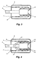
- a propelling tool 1 without a turbine is shown in Fig. 3 .
- the supply fluid is supplied to an ejector pump for driving the pump to suck cavity fluid in through the suction inlet 8.
- the cavity fluid and the supply fluid are subsequently let out through one and the same outlet functioning both as a supply outlet 7 and a suction outlet 9.
- the propelling tool 1 may be used together with a releasing means for releasing an element from the pipeline 3 or another cavity, which releasing means together with the propelling tool constitutes a releasing system 20.
- the releasing means may be a turbine 12 ejecting supply fluid directly into the cavity, a releasing tool 14, or a bypassing channel 17.
- a releasing system 20 without a turbine is shown in Fig. 4 .
- the supply fluid is partly let into the pump 10 and partly ejected through at least one ejection outlet 13 for a direct ejection of supply fluid into the cavity bypassing the pump 5 in order to release the precipitated solids 2 from the inside wall of the pipeline 3.
- the supply fluid let Into the pump drives the pump.
- the pressure on the ejected supply fluid is controlled by the size of the diameter of the ejection outlet 13.
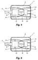
- FIG. 5 Another embodiment of the present invention comprising a turbine is shown in Fig. 5 , in which the turbine 12 ejects the supply fluid into the cavity bypassing the pump 5 in order to release the precipitated solids 2 with the highly pressurised supply fluid.
- the turbine 12 ejects the supply fluid into the cavity bypassing the pump 5 in order to release the precipitated solids 2 with the highly pressurised supply fluid.
- the pump 5 stops and is no longer driven by the turbine 12 since the supply fluid is ejected directly out into the pipeline 3.
- the turbine 12 has a bypassing means 16 so that the supply fluid is directed to bypass the turbine blades of the turbine 12 and transmit as much of the energy from the pressurised supply fluid as possible Into the pipeline 3.
- the bypassing means 16 may be any kind of direction means or control means, such as a valve.
- the supply fluid may also be let past the turbine in the same manner as shown In Fig. 4 through bypassing channels 17.
- the releasing system 20 is shown when the turbine 12 drives the pump 5 for sucking cavity fluid into the tool 1 in order to move the tool 1 forward to release precipitated solids 2.
- the releasing system stops and the pressurised supply fluid is directed to bypass the pump 5 and is ejected directly from the supply tubing 4 Into the cavity.
- the pressurised supply fluid is used to release the solids 2 as shown in Fig. 6 .
- the pressurised supply fluid is mixed with some kind of solvent.
- the releasing system continues to move forward In the pipeline 3.
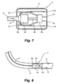
- the releasing system 20 further comprises a releasing tool 14 situated in front of the tool 1.
- the releasing tool 14 has a cutting edge, such as a blade, a knife, or the like cutting tool.
- the releasing tool 14 has a scraper.
- the scraper may have a plurality of arms, such as a slit cylinder, or just two arms like a fork.
- the scraper may also have some kind of projection extending radially out towards the side wall of the pipeline 3.
- the releasing tool 14 is situated in the front end of the tool 1 when moving forwarding the pipeline 3.
- the releasing tool 14 is connected to the shaft 15 between the turbine and the pump.
- the releasing tool 14 rotates with the pump 5 in order to release the precipitated solids 2.
- the releasing system 20 may have a sealing means 11 or flexible means 11 provided on the outside of the housing 5 for abutment against the inside wall of the pipeline 3.
- the sealing means or flexible means 11 is made of a flexible material, such as polymer, silicone, etc.
- the sealing means 11 is an O-ring, and in another the flexible means 11 is an inflatable means that is inflated, e.g. by the supply fluid.
- the flexible means 11 is inflated so as to diminish the passage of oil fluid along the outside of the tool, but not necessarily to abut the inside wall of the pipeline 3.
- the releasing system 20 of the present invention may also be used when a pipeline 3 has been blocked by a pipeline pig 19 being unable to pass precipitated solids 2 on the inside wall of the pipeline.
- the releasing system 20 may be provided with a drill bit situated on the shaft 15 of the tool for drilling its way through the pipeline pig as shown in Fig. 10 . Subsequently, the releasing system 20 is retracted from the pipeline and the drill bit is replaced with a fastening device 18 having a barb or a set of barbs which initially is in its collapsed or retracted position. The releasing system 20 is then submerged into the pipeline and moves forward in the same manner as mentioned above.
- the fastening device 18 with the retracted barb is placed in the hole drilled during the previous step.
- the barb exits on the other side of the pipeline plg as shown in Fig. 11 , the barb is unfolded or expanded. In this way, the releasing system 20 is able to retract the pipeline pig 19 when the system itself is retracted.
- the barb or set of barbs may have any kind of shape and be any kind of collapsible device being able to unfold when the fastening device 18 has penetrated the through-going hole of the pipeline pig, or a device being retractable into the shaft.
- the barb or set of barbs is unfolded just like an umbrella.
- the barb is constituted by two arms which are released and unfold when no longer pressed towards the shaft entering the through hole of the pig.
- the arms are made of a bendable material, such as metal or plastic, which is able to return to its originally shape when the stress is removed.
- the turbine 12 may be any kind of turbine able to convert energy from a flow of highly pressurised fluid into rotation of a pump.
- Precipitated solids 2 may be formed from any kind of fluid able to solidify within a pipeline or a like cavity.
- such solids 2 are solidified impurities in the oil or gas, such as ice or scales.
- Scales are formed due to the fact that the water constituents in the oil may comprise alkaline earth cations and anions, and water-insoluble scales are formed when cations and anions are present in a certain concentration.
Landscapes
- Engineering & Computer Science (AREA)
- Mechanical Engineering (AREA)
- Cleaning In General (AREA)
- Earth Drilling (AREA)
- Pipe Accessories (AREA)
- Portable Nailing Machines And Staplers (AREA)
- Ultra Sonic Daignosis Equipment (AREA)
Claims (11)
- Outil de propulsion (1) destiné à permettre un déplacement vers l'avant pour une opération dans un pipeline (3), dans un tubage, dans un puits, ou dans toute autre cavité, comprenant :- un tube d'approvisionnement (4) qui comprend un fluide d'approvisionnement sous pression ; et- un logement (5) connecté au tube d'approvisionnement, qui présente :- une entrée d'approvisionnement (6) disposée dans une extrémité arrière du logement et destinée à fournir le fluide d'approvisionnement sous pression en enfance du tube d'approvisionnement ;- une sortie d'approvisionnement (7) disposée dans une extrémité arrière du logement et destinés à l'éjection du fluide d'approvisionnement ; et- une entrée d'aspiration (8) ;dans lequel l'entrée d'aspiration est disposée dans l'extrémité avant pour une admission d'un fluide de cavité qui entoure l'outil dans le logement, et le logement comprend en outre :- une sortie d'aspiration (9) disposée dans l'extrémité arrière pour une sortie du fluide de cavité, et l'outil comprend en outre :u ne pompe (10) destinée à l'aspiration du fluide de cavité entrant par l'entrée d'aspiration et sortant par la sortie d'aspiration, la pompe étant entraînée par le fluide d'approvisionnement sous pression de façon à tirer l'outil vers l'avant dans une cavité.
- Outil de propulsion selon la revendication 1, dans lequel le logement présente des moyens d'étanchéité (11) pour une mise en butée contre la cavité, telle que le pipeline, le tubage, ou le puits.
- Outil de propulsion selon la revendication 1 ou la revendication 2, dans lequel une turbine (12) est positionnée entre l'entrée d'approvisionnement et la pompe, est connectée à la pompe par l'intermédiaire d'un arbre (15), et est entraînée par le fluide sous pression de façon à entraîner la pompe.
- Système de libération (20) destiné à libérer des solides précipités (2), tel que de la glace, des dépôts calcaires, et similaire dans un fluide de cavité dans un pipeline (3), dans un tubage, dans un puits, ou dans toute autre cavité, comprenant :- un outil de propulsion (1) selon l'une quelconque des revendications 1 à 3 ; et- un moyen de libération destiné à libérer les solides précipités de la cavité.
- Système de libération selon la revendication 4, dans lequel le moyen de libération est la turbine de l'outil de propulsion qui présente au moins une sortie d'éjection (13) pour une éjection directe du fluide d'approvisionnement dans la cavité en évitant la pompe de façon à libérer les solides précipitées de la cavité.
- Système de libération selon la revendication 4, dans lequel le moyen de libération est au moins un canal de dérivation (17) connecté de manière fluidique à l'entrée d'approvisionnement pour une orientation d'une partie du fluide d'approvisionnement qui sort à travers au moins une sortie d'éjection (13) en éjectant directement le fluide d'approvisionnement dans la cavité en éditant la pompe de façon à libérer les solides précipités de la cavité
- Système de libération selon la revendication 4, dans lequel le moyen de libération est un moyen de dérivation (16) en association avec la turbine qui permet une dérivation de la turbine de façon à éjecter le fluide sous pression directement dans la cavité à travers la sortie d'éjection (13).
- Système de libération selon l'une quelconque des revendications 4 à 7, dans lequel le fluide d'approvisionnement est de l'eau mélangée à n'importe quelle sorte d'alcool ou à toute autre sorte de solvant avant d'être éjecté à travers la sortie d'éjection.
- Système de libération selon l'une quelconque des revendications 4 à 8, dans lequel le moyen de libération est un outil de libération (14) disposé sur l'arbre devant l'outil de propulsion lors d'un déplacement en avant dans la cavité, et dans lequel l'outil de libération présente au moins un bord tranchant, un dispositif de raclage, un couteau, un soc, ou un outil de forage.
- Système de libération selon la revendication 4, dans lequel le moyen de libération est un dispositif de fixation (18) disposé sur l'arbre et destiné à être fixé sur un racleur de pipeline (19) et à libérer le racleur de pipeline et à le ramener à la surface.
- Système de libération selon la revendication 10, dans lequel le dispositif de fixation (18) présente au moines une pointe rétractable qui peut se rétracter dans l'arbre et se déployer lorsque le dispositif de fixation doit pénétrer dans un trou traversant dans le racleur de pipeline.
Priority Applications (10)
| Application Number | Priority Date | Filing Date | Title |
|---|---|---|---|
| AT09166428T ATE541651T1 (de) | 2009-07-27 | 2009-07-27 | Werkzeug mit antrieb |
| EP20090166428 EP2279802B1 (fr) | 2009-07-27 | 2009-07-27 | Outil avec propulsion |
| DK09166428T DK2279802T3 (da) | 2009-07-27 | 2009-07-27 | Fremdrivningsanordning |
| CA2769160A CA2769160A1 (fr) | 2009-07-27 | 2010-07-26 | Outil de propulsion |
| US13/386,190 US9114443B2 (en) | 2009-07-27 | 2010-07-26 | Propelling tool |
| AU2010277677A AU2010277677B2 (en) | 2009-07-27 | 2010-07-26 | Propelling tool |
| MX2012000627A MX2012000627A (es) | 2009-07-27 | 2010-07-26 | Herramienta propulsora. |
| CN201080032164.2A CN102470403B (zh) | 2009-07-27 | 2010-07-26 | 推进工具 |
| BR112012001694A BR112012001694A2 (pt) | 2009-07-27 | 2010-07-26 | ferramenta de propulsão |
| PCT/EP2010/060776 WO2011012566A1 (fr) | 2009-07-27 | 2010-07-26 | Outil de propulsion |
Applications Claiming Priority (1)
| Application Number | Priority Date | Filing Date | Title |
|---|---|---|---|
| EP20090166428 EP2279802B1 (fr) | 2009-07-27 | 2009-07-27 | Outil avec propulsion |
Publications (2)
| Publication Number | Publication Date |
|---|---|
| EP2279802A1 EP2279802A1 (fr) | 2011-02-02 |
| EP2279802B1 true EP2279802B1 (fr) | 2012-01-18 |
Family
ID=41565937
Family Applications (1)
| Application Number | Title | Priority Date | Filing Date |
|---|---|---|---|
| EP20090166428 Not-in-force EP2279802B1 (fr) | 2009-07-27 | 2009-07-27 | Outil avec propulsion |
Country Status (10)
| Country | Link |
|---|---|
| US (1) | US9114443B2 (fr) |
| EP (1) | EP2279802B1 (fr) |
| CN (1) | CN102470403B (fr) |
| AT (1) | ATE541651T1 (fr) |
| AU (1) | AU2010277677B2 (fr) |
| BR (1) | BR112012001694A2 (fr) |
| CA (1) | CA2769160A1 (fr) |
| DK (1) | DK2279802T3 (fr) |
| MX (1) | MX2012000627A (fr) |
| WO (1) | WO2011012566A1 (fr) |
Cited By (1)
| Publication number | Priority date | Publication date | Assignee | Title |
|---|---|---|---|---|
| EP4041464B1 (fr) * | 2019-10-09 | 2024-12-11 | Aquateq Sweden AB | Buse de nettoyage de l'intérieur d'un tuyau, système comprenant une telle buse et procédé de nettoyage de l'intérieur d'un tuyau |
Families Citing this family (16)
| Publication number | Priority date | Publication date | Assignee | Title |
|---|---|---|---|---|
| JP5658583B2 (ja) * | 2011-01-31 | 2015-01-28 | 大阪瓦斯株式会社 | 管路内ピグ移動装置、並びに、その管路内ピグ移動装置を用いた管路内残留ガス排気方法、管路内検査方法、管路内面ライニング方法、管路内洗浄方法及び管路内通線方法 |
| JP2016531282A (ja) * | 2013-06-26 | 2016-10-06 | アレンティック マイクロサイエンス インコーポレイテッド | 顕微鏡法に関するサンプル処理の改善 |
| CN104438245B (zh) * | 2014-09-29 | 2016-05-25 | 中国石化集团胜利石油管理局海上石油工程技术检验中心 | 海洋管道清洗装置 |
| CN104499563A (zh) * | 2014-12-18 | 2015-04-08 | 廉建会 | 一种管道疏通清理设备 |
| CN105371051A (zh) * | 2015-12-02 | 2016-03-02 | 上海大学 | 管道修理机器人推送装置 |
| EP3241624B1 (fr) * | 2016-05-06 | 2022-01-26 | Wolftank-Adisa Holding AG | Appareil et procédé pour vider un réservoir |
| US9631347B1 (en) * | 2016-08-29 | 2017-04-25 | Mell H. Kuhn | System and method for stabilizing chlorine residual in a dead end water main |
| CN106733964B (zh) * | 2017-01-12 | 2018-12-11 | 锐驰高科股份有限公司 | 废弃原油管道无害化清洗工艺 |
| CN107185922A (zh) * | 2017-06-16 | 2017-09-22 | 成都金玉雄辉建筑工程有限公司 | 顶管内壁清洁装置 |
| US20180361439A1 (en) * | 2017-06-16 | 2018-12-20 | Benton Frederick Baugh | Local vacuum method for advancing a pipeline remediation pig |
| CN109681720A (zh) * | 2018-12-29 | 2019-04-26 | 成都普崔克机电有限公司 | 一种流体驱动的软体管道单元 |
| CN109500014A (zh) * | 2019-01-21 | 2019-03-22 | 刘珊珊 | 一种直径可调节的管道清洗机器人 |
| CN109877074B (zh) * | 2019-03-11 | 2023-12-12 | 中广核新能源投资(深圳)有限公司 | 一种非能动光伏组件的清洗装置 |
| CN113622504B (zh) * | 2021-08-23 | 2023-04-04 | 中冶建工集团有限公司 | 能适应各种管径的管道清淤装置 |
| CN115055455B (zh) * | 2022-06-09 | 2023-05-16 | 江阴市人民医院 | 一种外科护理用的辅助清洗设备 |
| CN115254819A (zh) * | 2022-07-14 | 2022-11-01 | 中国民用航空飞行学院 | 一种基于流体力学的旋转涡轮叶片清洗刀具 |
Family Cites Families (7)
| Publication number | Priority date | Publication date | Assignee | Title |
|---|---|---|---|---|
| SE446159B (sv) * | 1984-05-24 | 1986-08-18 | Bo Larsson | Vandrande hydrodynamiskt munstycke for tryckvattenrengoring av vatten-, avlopps- och dagvattenledningar |
| US5143105A (en) * | 1991-08-12 | 1992-09-01 | Shinzou Katayama | Cleaning device for tube |
| US6651744B1 (en) * | 1997-11-21 | 2003-11-25 | Superior Services, Llc | Bi-directional thruster pig apparatus and method of utilizing same |
| DE19915413B4 (de) | 1998-04-07 | 2014-08-07 | Emilia Steinicke | Düsenkörper für ein Reinigungsgerät |
| US8434182B2 (en) * | 1999-01-25 | 2013-05-07 | Aqua Products, Inc. | Pool cleaner with high pressure cleaning jets |
| AUPR973101A0 (en) * | 2001-12-21 | 2002-01-24 | Morden, Donald R | High pressure rotary pipe "line" cleaner |
| SE531509C2 (sv) * | 2007-08-31 | 2009-05-05 | Bo Larsson Med Bl Consult Bo L | Hydrodynamiskt munstycke |
-
2009
- 2009-07-27 EP EP20090166428 patent/EP2279802B1/fr not_active Not-in-force
- 2009-07-27 AT AT09166428T patent/ATE541651T1/de active
- 2009-07-27 DK DK09166428T patent/DK2279802T3/da active
-
2010
- 2010-07-26 BR BR112012001694A patent/BR112012001694A2/pt not_active IP Right Cessation
- 2010-07-26 WO PCT/EP2010/060776 patent/WO2011012566A1/fr not_active Ceased
- 2010-07-26 CA CA2769160A patent/CA2769160A1/fr not_active Abandoned
- 2010-07-26 US US13/386,190 patent/US9114443B2/en not_active Expired - Fee Related
- 2010-07-26 MX MX2012000627A patent/MX2012000627A/es active IP Right Grant
- 2010-07-26 CN CN201080032164.2A patent/CN102470403B/zh not_active Expired - Fee Related
- 2010-07-26 AU AU2010277677A patent/AU2010277677B2/en not_active Ceased
Cited By (1)
| Publication number | Priority date | Publication date | Assignee | Title |
|---|---|---|---|---|
| EP4041464B1 (fr) * | 2019-10-09 | 2024-12-11 | Aquateq Sweden AB | Buse de nettoyage de l'intérieur d'un tuyau, système comprenant une telle buse et procédé de nettoyage de l'intérieur d'un tuyau |
Also Published As
| Publication number | Publication date |
|---|---|
| CN102470403A (zh) | 2012-05-23 |
| CN102470403B (zh) | 2014-09-17 |
| CA2769160A1 (fr) | 2011-02-03 |
| WO2011012566A1 (fr) | 2011-02-03 |
| US20120132238A1 (en) | 2012-05-31 |
| EP2279802A1 (fr) | 2011-02-02 |
| MX2012000627A (es) | 2012-01-27 |
| DK2279802T3 (da) | 2012-05-14 |
| BR112012001694A2 (pt) | 2016-04-12 |
| AU2010277677B2 (en) | 2013-03-07 |
| US9114443B2 (en) | 2015-08-25 |
| AU2010277677A1 (en) | 2012-03-15 |
| ATE541651T1 (de) | 2012-02-15 |
Similar Documents
| Publication | Publication Date | Title |
|---|---|---|
| EP2279802B1 (fr) | Outil avec propulsion | |
| EP2122106B1 (fr) | Outil de forage à nettoyeur de liquide | |
| US10221639B2 (en) | Deviated/horizontal well propulsion for downhole devices | |
| CA2758495C (fr) | Systeme de gestion de debris transportes au moyen d'un cable lisse | |
| US8056622B2 (en) | Slickline conveyed debris management system | |
| DK2516793T3 (en) | Borehole cleaning tools or moving fluid in a wellbore | |
| US4047581A (en) | Multistage, downhole, turbo-powered intensifier for drilling petroleum wells | |
| EP0927286B1 (fr) | Drague | |
| US20150308232A1 (en) | Downhole cleaning system | |
| CN1777720B (zh) | 清除海底钻井钻中出泥沙的装置 | |
| AU2013373842B2 (en) | Device for conveying away drillings | |
| CN121803174A (zh) | 一种水下岩芯钻探碎屑高效排出装置及方法 | |
| JPH11223088A (ja) | 掘進機及びそれを使用した管引込み工法 | |
| JPH1136437A (ja) | 自走式下水管内堆積物除去装置 | |
| JPS6125880B2 (fr) |
Legal Events
| Date | Code | Title | Description |
|---|---|---|---|
| PUAI | Public reference made under article 153(3) epc to a published international application that has entered the european phase |
Free format text: ORIGINAL CODE: 0009012 |
|
| AK | Designated contracting states |
Kind code of ref document: A1 Designated state(s): AT BE BG CH CY CZ DE DK EE ES FI FR GB GR HR HU IE IS IT LI LT LU LV MC MK MT NL NO PL PT RO SE SI SK SM TR |
|
| GRAP | Despatch of communication of intention to grant a patent |
Free format text: ORIGINAL CODE: EPIDOSNIGR1 |
|
| 17P | Request for examination filed |
Effective date: 20110728 |
|
| GRAS | Grant fee paid |
Free format text: ORIGINAL CODE: EPIDOSNIGR3 |
|
| GRAA | (expected) grant |
Free format text: ORIGINAL CODE: 0009210 |
|
| AK | Designated contracting states |
Kind code of ref document: B1 Designated state(s): AT BE BG CH CY CZ DE DK EE ES FI FR GB GR HR HU IE IS IT LI LT LU LV MC MK MT NL NO PL PT RO SE SI SK SM TR |
|
| REG | Reference to a national code |
Ref country code: GB Ref legal event code: FG4D |
|
| REG | Reference to a national code |
Ref country code: CH Ref legal event code: EP |
|
| REG | Reference to a national code |
Ref country code: AT Ref legal event code: REF Ref document number: 541651 Country of ref document: AT Kind code of ref document: T Effective date: 20120215 Ref country code: IE Ref legal event code: FG4D |
|
| REG | Reference to a national code |
Ref country code: DE Ref legal event code: R096 Ref document number: 602009004700 Country of ref document: DE Effective date: 20120315 |
|
| REG | Reference to a national code |
Ref country code: NL Ref legal event code: T3 |
|
| REG | Reference to a national code |
Ref country code: DK Ref legal event code: T3 |
|
| REG | Reference to a national code |
Ref country code: NO Ref legal event code: T2 Effective date: 20120118 |
|
| LTIE | Lt: invalidation of european patent or patent extension |
Effective date: 20120118 |
|
| PG25 | Lapsed in a contracting state [announced via postgrant information from national office to epo] |
Ref country code: BG Free format text: LAPSE BECAUSE OF FAILURE TO SUBMIT A TRANSLATION OF THE DESCRIPTION OR TO PAY THE FEE WITHIN THE PRESCRIBED TIME-LIMIT Effective date: 20120418 Ref country code: BE Free format text: LAPSE BECAUSE OF FAILURE TO SUBMIT A TRANSLATION OF THE DESCRIPTION OR TO PAY THE FEE WITHIN THE PRESCRIBED TIME-LIMIT Effective date: 20120118 Ref country code: LT Free format text: LAPSE BECAUSE OF FAILURE TO SUBMIT A TRANSLATION OF THE DESCRIPTION OR TO PAY THE FEE WITHIN THE PRESCRIBED TIME-LIMIT Effective date: 20120118 Ref country code: HR Free format text: LAPSE BECAUSE OF FAILURE TO SUBMIT A TRANSLATION OF THE DESCRIPTION OR TO PAY THE FEE WITHIN THE PRESCRIBED TIME-LIMIT Effective date: 20120118 Ref country code: IS Free format text: LAPSE BECAUSE OF FAILURE TO SUBMIT A TRANSLATION OF THE DESCRIPTION OR TO PAY THE FEE WITHIN THE PRESCRIBED TIME-LIMIT Effective date: 20120518 |
|
| PG25 | Lapsed in a contracting state [announced via postgrant information from national office to epo] |
Ref country code: FI Free format text: LAPSE BECAUSE OF FAILURE TO SUBMIT A TRANSLATION OF THE DESCRIPTION OR TO PAY THE FEE WITHIN THE PRESCRIBED TIME-LIMIT Effective date: 20120118 Ref country code: GR Free format text: LAPSE BECAUSE OF FAILURE TO SUBMIT A TRANSLATION OF THE DESCRIPTION OR TO PAY THE FEE WITHIN THE PRESCRIBED TIME-LIMIT Effective date: 20120419 Ref country code: PL Free format text: LAPSE BECAUSE OF FAILURE TO SUBMIT A TRANSLATION OF THE DESCRIPTION OR TO PAY THE FEE WITHIN THE PRESCRIBED TIME-LIMIT Effective date: 20120118 Ref country code: PT Free format text: LAPSE BECAUSE OF FAILURE TO SUBMIT A TRANSLATION OF THE DESCRIPTION OR TO PAY THE FEE WITHIN THE PRESCRIBED TIME-LIMIT Effective date: 20120518 Ref country code: LV Free format text: LAPSE BECAUSE OF FAILURE TO SUBMIT A TRANSLATION OF THE DESCRIPTION OR TO PAY THE FEE WITHIN THE PRESCRIBED TIME-LIMIT Effective date: 20120118 |
|
| REG | Reference to a national code |
Ref country code: AT Ref legal event code: MK05 Ref document number: 541651 Country of ref document: AT Kind code of ref document: T Effective date: 20120118 |
|
| PG25 | Lapsed in a contracting state [announced via postgrant information from national office to epo] |
Ref country code: CY Free format text: LAPSE BECAUSE OF FAILURE TO SUBMIT A TRANSLATION OF THE DESCRIPTION OR TO PAY THE FEE WITHIN THE PRESCRIBED TIME-LIMIT Effective date: 20120118 |
|
| REG | Reference to a national code |
Ref country code: HU Ref legal event code: AG4A Ref document number: E013990 Country of ref document: HU |
|
| PG25 | Lapsed in a contracting state [announced via postgrant information from national office to epo] |
Ref country code: EE Free format text: LAPSE BECAUSE OF FAILURE TO SUBMIT A TRANSLATION OF THE DESCRIPTION OR TO PAY THE FEE WITHIN THE PRESCRIBED TIME-LIMIT Effective date: 20120118 Ref country code: CZ Free format text: LAPSE BECAUSE OF FAILURE TO SUBMIT A TRANSLATION OF THE DESCRIPTION OR TO PAY THE FEE WITHIN THE PRESCRIBED TIME-LIMIT Effective date: 20120118 Ref country code: SI Free format text: LAPSE BECAUSE OF FAILURE TO SUBMIT A TRANSLATION OF THE DESCRIPTION OR TO PAY THE FEE WITHIN THE PRESCRIBED TIME-LIMIT Effective date: 20120118 Ref country code: RO Free format text: LAPSE BECAUSE OF FAILURE TO SUBMIT A TRANSLATION OF THE DESCRIPTION OR TO PAY THE FEE WITHIN THE PRESCRIBED TIME-LIMIT Effective date: 20120118 Ref country code: SE Free format text: LAPSE BECAUSE OF FAILURE TO SUBMIT A TRANSLATION OF THE DESCRIPTION OR TO PAY THE FEE WITHIN THE PRESCRIBED TIME-LIMIT Effective date: 20120118 |
|
| PLBE | No opposition filed within time limit |
Free format text: ORIGINAL CODE: 0009261 |
|
| STAA | Information on the status of an ep patent application or granted ep patent |
Free format text: STATUS: NO OPPOSITION FILED WITHIN TIME LIMIT |
|
| PG25 | Lapsed in a contracting state [announced via postgrant information from national office to epo] |
Ref country code: SK Free format text: LAPSE BECAUSE OF FAILURE TO SUBMIT A TRANSLATION OF THE DESCRIPTION OR TO PAY THE FEE WITHIN THE PRESCRIBED TIME-LIMIT Effective date: 20120118 Ref country code: IT Free format text: LAPSE BECAUSE OF FAILURE TO SUBMIT A TRANSLATION OF THE DESCRIPTION OR TO PAY THE FEE WITHIN THE PRESCRIBED TIME-LIMIT Effective date: 20120118 |
|
| 26N | No opposition filed |
Effective date: 20121019 |
|
| PG25 | Lapsed in a contracting state [announced via postgrant information from national office to epo] |
Ref country code: AT Free format text: LAPSE BECAUSE OF FAILURE TO SUBMIT A TRANSLATION OF THE DESCRIPTION OR TO PAY THE FEE WITHIN THE PRESCRIBED TIME-LIMIT Effective date: 20120118 |
|
| REG | Reference to a national code |
Ref country code: DE Ref legal event code: R097 Ref document number: 602009004700 Country of ref document: DE Effective date: 20121019 |
|
| PG25 | Lapsed in a contracting state [announced via postgrant information from national office to epo] |
Ref country code: MC Free format text: LAPSE BECAUSE OF NON-PAYMENT OF DUE FEES Effective date: 20120731 Ref country code: MK Free format text: LAPSE BECAUSE OF FAILURE TO SUBMIT A TRANSLATION OF THE DESCRIPTION OR TO PAY THE FEE WITHIN THE PRESCRIBED TIME-LIMIT Effective date: 20120118 |
|
| PG25 | Lapsed in a contracting state [announced via postgrant information from national office to epo] |
Ref country code: ES Free format text: LAPSE BECAUSE OF FAILURE TO SUBMIT A TRANSLATION OF THE DESCRIPTION OR TO PAY THE FEE WITHIN THE PRESCRIBED TIME-LIMIT Effective date: 20120429 |
|
| REG | Reference to a national code |
Ref country code: IE Ref legal event code: MM4A |
|
| PG25 | Lapsed in a contracting state [announced via postgrant information from national office to epo] |
Ref country code: MT Free format text: LAPSE BECAUSE OF FAILURE TO SUBMIT A TRANSLATION OF THE DESCRIPTION OR TO PAY THE FEE WITHIN THE PRESCRIBED TIME-LIMIT Effective date: 20120118 Ref country code: IE Free format text: LAPSE BECAUSE OF NON-PAYMENT OF DUE FEES Effective date: 20120727 |
|
| REG | Reference to a national code |
Ref country code: CH Ref legal event code: PL |
|
| PG25 | Lapsed in a contracting state [announced via postgrant information from national office to epo] |
Ref country code: LI Free format text: LAPSE BECAUSE OF NON-PAYMENT OF DUE FEES Effective date: 20130731 Ref country code: CH Free format text: LAPSE BECAUSE OF NON-PAYMENT OF DUE FEES Effective date: 20130731 Ref country code: TR Free format text: LAPSE BECAUSE OF FAILURE TO SUBMIT A TRANSLATION OF THE DESCRIPTION OR TO PAY THE FEE WITHIN THE PRESCRIBED TIME-LIMIT Effective date: 20120118 |
|
| PG25 | Lapsed in a contracting state [announced via postgrant information from national office to epo] |
Ref country code: SM Free format text: LAPSE BECAUSE OF FAILURE TO SUBMIT A TRANSLATION OF THE DESCRIPTION OR TO PAY THE FEE WITHIN THE PRESCRIBED TIME-LIMIT Effective date: 20120118 Ref country code: LU Free format text: LAPSE BECAUSE OF NON-PAYMENT OF DUE FEES Effective date: 20120727 |
|
| REG | Reference to a national code |
Ref country code: FR Ref legal event code: PLFP Year of fee payment: 8 |
|
| PGFP | Annual fee paid to national office [announced via postgrant information from national office to epo] |
Ref country code: NL Payment date: 20160714 Year of fee payment: 8 |
|
| PGFP | Annual fee paid to national office [announced via postgrant information from national office to epo] |
Ref country code: NO Payment date: 20160719 Year of fee payment: 8 Ref country code: GB Payment date: 20160719 Year of fee payment: 8 Ref country code: DE Payment date: 20160722 Year of fee payment: 8 Ref country code: DK Payment date: 20160721 Year of fee payment: 8 |
|
| PGFP | Annual fee paid to national office [announced via postgrant information from national office to epo] |
Ref country code: FR Payment date: 20160727 Year of fee payment: 8 Ref country code: HU Payment date: 20160627 Year of fee payment: 8 |
|
| REG | Reference to a national code |
Ref country code: DE Ref legal event code: R119 Ref document number: 602009004700 Country of ref document: DE |
|
| REG | Reference to a national code |
Ref country code: DK Ref legal event code: EBP Effective date: 20170731 Ref country code: NO Ref legal event code: MMEP |
|
| REG | Reference to a national code |
Ref country code: NL Ref legal event code: MM Effective date: 20170801 |
|
| GBPC | Gb: european patent ceased through non-payment of renewal fee |
Effective date: 20170727 |
|
| REG | Reference to a national code |
Ref country code: FR Ref legal event code: ST Effective date: 20180330 |
|
| PG25 | Lapsed in a contracting state [announced via postgrant information from national office to epo] |
Ref country code: GB Free format text: LAPSE BECAUSE OF NON-PAYMENT OF DUE FEES Effective date: 20170727 Ref country code: NO Free format text: LAPSE BECAUSE OF NON-PAYMENT OF DUE FEES Effective date: 20170731 Ref country code: HU Free format text: LAPSE BECAUSE OF NON-PAYMENT OF DUE FEES Effective date: 20170728 Ref country code: DE Free format text: LAPSE BECAUSE OF NON-PAYMENT OF DUE FEES Effective date: 20180201 Ref country code: NL Free format text: LAPSE BECAUSE OF NON-PAYMENT OF DUE FEES Effective date: 20170801 |
|
| PG25 | Lapsed in a contracting state [announced via postgrant information from national office to epo] |
Ref country code: FR Free format text: LAPSE BECAUSE OF NON-PAYMENT OF DUE FEES Effective date: 20170731 |
|
| PG25 | Lapsed in a contracting state [announced via postgrant information from national office to epo] |
Ref country code: DK Free format text: LAPSE BECAUSE OF NON-PAYMENT OF DUE FEES Effective date: 20170731 |