EP2279923A2 - Procédé d'assistance au conducteur d'un véhicule automobile lors d'un procédé de propulsion et véhicule automobile - Google Patents
Procédé d'assistance au conducteur d'un véhicule automobile lors d'un procédé de propulsion et véhicule automobile Download PDFInfo
- Publication number
- EP2279923A2 EP2279923A2 EP10006863A EP10006863A EP2279923A2 EP 2279923 A2 EP2279923 A2 EP 2279923A2 EP 10006863 A EP10006863 A EP 10006863A EP 10006863 A EP10006863 A EP 10006863A EP 2279923 A2 EP2279923 A2 EP 2279923A2
- Authority
- EP
- European Patent Office
- Prior art keywords
- motor vehicle
- travel
- driver
- vehicle
- stabilizing
- Prior art date
- Legal status (The legal status is an assumption and is not a legal conclusion. Google has not performed a legal analysis and makes no representation as to the accuracy of the status listed.)
- Withdrawn
Links
Images

Classifications
-
- B—PERFORMING OPERATIONS; TRANSPORTING
- B60—VEHICLES IN GENERAL
- B60K—ARRANGEMENT OR MOUNTING OF PROPULSION UNITS OR OF TRANSMISSIONS IN VEHICLES; ARRANGEMENT OR MOUNTING OF PLURAL DIVERSE PRIME-MOVERS IN VEHICLES; AUXILIARY DRIVES FOR VEHICLES; INSTRUMENTATION OR DASHBOARDS FOR VEHICLES; ARRANGEMENTS IN CONNECTION WITH COOLING, AIR INTAKE, GAS EXHAUST OR FUEL SUPPLY OF PROPULSION UNITS IN VEHICLES
- B60K35/00—Instruments specially adapted for vehicles; Arrangement of instruments in or on vehicles
- B60K35/20—Output arrangements, i.e. from vehicle to user, associated with vehicle functions or specially adapted therefor
- B60K35/28—Output arrangements, i.e. from vehicle to user, associated with vehicle functions or specially adapted therefor characterised by the type of the output information, e.g. video entertainment or vehicle dynamics information; characterised by the purpose of the output information, e.g. for attracting the attention of the driver
-
- B—PERFORMING OPERATIONS; TRANSPORTING
- B60—VEHICLES IN GENERAL
- B60W—CONJOINT CONTROL OF VEHICLE SUB-UNITS OF DIFFERENT TYPE OR DIFFERENT FUNCTION; CONTROL SYSTEMS SPECIALLY ADAPTED FOR HYBRID VEHICLES; ROAD VEHICLE DRIVE CONTROL SYSTEMS FOR PURPOSES NOT RELATED TO THE CONTROL OF A PARTICULAR SUB-UNIT
- B60W50/00—Details of control systems for road vehicle drive control not related to the control of a particular sub-unit, e.g. process diagnostic or vehicle driver interfaces
- B60W50/08—Interaction between the driver and the control system
- B60W50/14—Means for informing the driver, warning the driver or prompting a driver intervention
-
- B—PERFORMING OPERATIONS; TRANSPORTING
- B60—VEHICLES IN GENERAL
- B60K—ARRANGEMENT OR MOUNTING OF PROPULSION UNITS OR OF TRANSMISSIONS IN VEHICLES; ARRANGEMENT OR MOUNTING OF PLURAL DIVERSE PRIME-MOVERS IN VEHICLES; AUXILIARY DRIVES FOR VEHICLES; INSTRUMENTATION OR DASHBOARDS FOR VEHICLES; ARRANGEMENTS IN CONNECTION WITH COOLING, AIR INTAKE, GAS EXHAUST OR FUEL SUPPLY OF PROPULSION UNITS IN VEHICLES
- B60K35/00—Instruments specially adapted for vehicles; Arrangement of instruments in or on vehicles
- B60K35/20—Output arrangements, i.e. from vehicle to user, associated with vehicle functions or specially adapted therefor
-
- B—PERFORMING OPERATIONS; TRANSPORTING
- B60—VEHICLES IN GENERAL
- B60K—ARRANGEMENT OR MOUNTING OF PROPULSION UNITS OR OF TRANSMISSIONS IN VEHICLES; ARRANGEMENT OR MOUNTING OF PLURAL DIVERSE PRIME-MOVERS IN VEHICLES; AUXILIARY DRIVES FOR VEHICLES; INSTRUMENTATION OR DASHBOARDS FOR VEHICLES; ARRANGEMENTS IN CONNECTION WITH COOLING, AIR INTAKE, GAS EXHAUST OR FUEL SUPPLY OF PROPULSION UNITS IN VEHICLES
- B60K35/00—Instruments specially adapted for vehicles; Arrangement of instruments in or on vehicles
- B60K35/20—Output arrangements, i.e. from vehicle to user, associated with vehicle functions or specially adapted therefor
- B60K35/21—Output arrangements, i.e. from vehicle to user, associated with vehicle functions or specially adapted therefor using visual output, e.g. blinking lights or matrix displays
- B60K35/23—Head-up displays [HUD]
-
- B—PERFORMING OPERATIONS; TRANSPORTING
- B60—VEHICLES IN GENERAL
- B60K—ARRANGEMENT OR MOUNTING OF PROPULSION UNITS OR OF TRANSMISSIONS IN VEHICLES; ARRANGEMENT OR MOUNTING OF PLURAL DIVERSE PRIME-MOVERS IN VEHICLES; AUXILIARY DRIVES FOR VEHICLES; INSTRUMENTATION OR DASHBOARDS FOR VEHICLES; ARRANGEMENTS IN CONNECTION WITH COOLING, AIR INTAKE, GAS EXHAUST OR FUEL SUPPLY OF PROPULSION UNITS IN VEHICLES
- B60K35/00—Instruments specially adapted for vehicles; Arrangement of instruments in or on vehicles
- B60K35/80—Arrangements for controlling instruments
-
- B—PERFORMING OPERATIONS; TRANSPORTING
- B60—VEHICLES IN GENERAL
- B60Q—ARRANGEMENT OF SIGNALLING OR LIGHTING DEVICES, THE MOUNTING OR SUPPORTING THEREOF OR CIRCUITS THEREFOR, FOR VEHICLES IN GENERAL
- B60Q1/00—Arrangement of optical signalling or lighting devices, the mounting or supporting thereof or circuits therefor
- B60Q1/02—Arrangement of optical signalling or lighting devices, the mounting or supporting thereof or circuits therefor the devices being primarily intended to illuminate the way ahead or to illuminate other areas of way or environments
- B60Q1/04—Arrangement of optical signalling or lighting devices, the mounting or supporting thereof or circuits therefor the devices being primarily intended to illuminate the way ahead or to illuminate other areas of way or environments the devices being headlights
- B60Q1/06—Arrangement of optical signalling or lighting devices, the mounting or supporting thereof or circuits therefor the devices being primarily intended to illuminate the way ahead or to illuminate other areas of way or environments the devices being headlights adjustable, e.g. remotely-controlled from inside vehicle
- B60Q1/08—Arrangement of optical signalling or lighting devices, the mounting or supporting thereof or circuits therefor the devices being primarily intended to illuminate the way ahead or to illuminate other areas of way or environments the devices being headlights adjustable, e.g. remotely-controlled from inside vehicle automatically
- B60Q1/085—Arrangement of optical signalling or lighting devices, the mounting or supporting thereof or circuits therefor the devices being primarily intended to illuminate the way ahead or to illuminate other areas of way or environments the devices being headlights adjustable, e.g. remotely-controlled from inside vehicle automatically due to special conditions, e.g. adverse weather, type of road, badly illuminated road signs or potential dangers
-
- B—PERFORMING OPERATIONS; TRANSPORTING
- B60—VEHICLES IN GENERAL
- B60W—CONJOINT CONTROL OF VEHICLE SUB-UNITS OF DIFFERENT TYPE OR DIFFERENT FUNCTION; CONTROL SYSTEMS SPECIALLY ADAPTED FOR HYBRID VEHICLES; ROAD VEHICLE DRIVE CONTROL SYSTEMS FOR PURPOSES NOT RELATED TO THE CONTROL OF A PARTICULAR SUB-UNIT
- B60W30/00—Purposes of road vehicle drive control systems not related to the control of a particular sub-unit, e.g. of systems using conjoint control of vehicle sub-units
- B60W30/02—Control of vehicle driving stability
-
- B—PERFORMING OPERATIONS; TRANSPORTING
- B62—LAND VEHICLES FOR TRAVELLING OTHERWISE THAN ON RAILS
- B62D—MOTOR VEHICLES; TRAILERS
- B62D15/00—Steering not otherwise provided for
- B62D15/02—Steering position indicators ; Steering position determination; Steering aids
- B62D15/029—Steering assistants using warnings or proposing actions to the driver without influencing the steering system
-
- B—PERFORMING OPERATIONS; TRANSPORTING
- B60—VEHICLES IN GENERAL
- B60K—ARRANGEMENT OR MOUNTING OF PROPULSION UNITS OR OF TRANSMISSIONS IN VEHICLES; ARRANGEMENT OR MOUNTING OF PLURAL DIVERSE PRIME-MOVERS IN VEHICLES; AUXILIARY DRIVES FOR VEHICLES; INSTRUMENTATION OR DASHBOARDS FOR VEHICLES; ARRANGEMENTS IN CONNECTION WITH COOLING, AIR INTAKE, GAS EXHAUST OR FUEL SUPPLY OF PROPULSION UNITS IN VEHICLES
- B60K2360/00—Indexing scheme associated with groups B60K35/00 or B60K37/00 relating to details of instruments or dashboards
- B60K2360/77—Instrument locations other than the dashboard
- B60K2360/785—Instrument locations other than the dashboard on or in relation to the windshield or windows
-
- B—PERFORMING OPERATIONS; TRANSPORTING
- B60—VEHICLES IN GENERAL
- B60Q—ARRANGEMENT OF SIGNALLING OR LIGHTING DEVICES, THE MOUNTING OR SUPPORTING THEREOF OR CIRCUITS THEREFOR, FOR VEHICLES IN GENERAL
- B60Q2300/00—Indexing codes for automatically adjustable headlamps or automatically dimmable headlamps
- B60Q2300/10—Indexing codes relating to particular vehicle conditions
- B60Q2300/12—Steering parameters
- B60Q2300/122—Steering angle
-
- B—PERFORMING OPERATIONS; TRANSPORTING
- B60—VEHICLES IN GENERAL
- B60Q—ARRANGEMENT OF SIGNALLING OR LIGHTING DEVICES, THE MOUNTING OR SUPPORTING THEREOF OR CIRCUITS THEREFOR, FOR VEHICLES IN GENERAL
- B60Q2300/00—Indexing codes for automatically adjustable headlamps or automatically dimmable headlamps
- B60Q2300/10—Indexing codes relating to particular vehicle conditions
- B60Q2300/13—Attitude of the vehicle body
- B60Q2300/134—Yaw
-
- B—PERFORMING OPERATIONS; TRANSPORTING
- B60—VEHICLES IN GENERAL
- B60Q—ARRANGEMENT OF SIGNALLING OR LIGHTING DEVICES, THE MOUNTING OR SUPPORTING THEREOF OR CIRCUITS THEREFOR, FOR VEHICLES IN GENERAL
- B60Q2300/00—Indexing codes for automatically adjustable headlamps or automatically dimmable headlamps
- B60Q2300/40—Indexing codes relating to other road users or special conditions
- B60Q2300/45—Special conditions, e.g. pedestrians, road signs or potential dangers
-
- B—PERFORMING OPERATIONS; TRANSPORTING
- B60—VEHICLES IN GENERAL
- B60W—CONJOINT CONTROL OF VEHICLE SUB-UNITS OF DIFFERENT TYPE OR DIFFERENT FUNCTION; CONTROL SYSTEMS SPECIALLY ADAPTED FOR HYBRID VEHICLES; ROAD VEHICLE DRIVE CONTROL SYSTEMS FOR PURPOSES NOT RELATED TO THE CONTROL OF A PARTICULAR SUB-UNIT
- B60W50/00—Details of control systems for road vehicle drive control not related to the control of a particular sub-unit, e.g. process diagnostic or vehicle driver interfaces
- B60W50/08—Interaction between the driver and the control system
- B60W50/14—Means for informing the driver, warning the driver or prompting a driver intervention
- B60W2050/146—Display means
-
- B—PERFORMING OPERATIONS; TRANSPORTING
- B60—VEHICLES IN GENERAL
- B60W—CONJOINT CONTROL OF VEHICLE SUB-UNITS OF DIFFERENT TYPE OR DIFFERENT FUNCTION; CONTROL SYSTEMS SPECIALLY ADAPTED FOR HYBRID VEHICLES; ROAD VEHICLE DRIVE CONTROL SYSTEMS FOR PURPOSES NOT RELATED TO THE CONTROL OF A PARTICULAR SUB-UNIT
- B60W2520/00—Input parameters relating to overall vehicle dynamics
- B60W2520/14—Yaw
-
- B—PERFORMING OPERATIONS; TRANSPORTING
- B60—VEHICLES IN GENERAL
- B60W—CONJOINT CONTROL OF VEHICLE SUB-UNITS OF DIFFERENT TYPE OR DIFFERENT FUNCTION; CONTROL SYSTEMS SPECIALLY ADAPTED FOR HYBRID VEHICLES; ROAD VEHICLE DRIVE CONTROL SYSTEMS FOR PURPOSES NOT RELATED TO THE CONTROL OF A PARTICULAR SUB-UNIT
- B60W2520/00—Input parameters relating to overall vehicle dynamics
- B60W2520/20—Sideslip angle
-
- B—PERFORMING OPERATIONS; TRANSPORTING
- B60—VEHICLES IN GENERAL
- B60W—CONJOINT CONTROL OF VEHICLE SUB-UNITS OF DIFFERENT TYPE OR DIFFERENT FUNCTION; CONTROL SYSTEMS SPECIALLY ADAPTED FOR HYBRID VEHICLES; ROAD VEHICLE DRIVE CONTROL SYSTEMS FOR PURPOSES NOT RELATED TO THE CONTROL OF A PARTICULAR SUB-UNIT
- B60W2540/00—Input parameters relating to occupants
- B60W2540/18—Steering angle
Definitions
- the invention relates to a method for assisting a driver of a motor vehicle during a spin operation as well as a motor vehicle.
- chassis control systems are known.
- the best known example of this are the so-called ESP systems (Electronic Stability Program, often also ESC - Electronic Stability Control).
- ESP systems Electronic Stability Program, often also ESC - Electronic Stability Control.
- Such systems attempt to prevent a spinning of the vehicle by selectively braking individual wheels or to end a spin state as quickly as possible in order to give the driver control of the vehicle.
- the ESP system or the control unit assigned to it compares constantly, for example up to 100 times per second, the actual state of the motor vehicle with the driver's request, by considering driving dynamics descriptive parameters.
- a steering angle sensor provides the driver's request with respect to the direction of travel
- acceleration sensors, yaw rate sensors and speed sensors often additionally also a lateral acceleration sensor, provide data on the actual driving dynamics characteristics of the motor vehicle.
- the ESP system can calculate the target rotational rate and compare it with the actual rotational rate in order to detect a spin state and initiate appropriate countermeasures, which can then be transferred to a brake control device, for example, if the latter is not already integrated in the ESP system.
- the driving dynamics descriptive parameters are determined, evaluated with regard to a spin state and initiated countermeasures mainly with respect to braking actions. It is also common practice that other parameters are determined by suspension control systems, for example, a slip angle, so the angle by which the motor vehicle has rotated from the desired direction, the float angle velocity or the yaw angle deviation. These parameters can then be used, for example, to calculate restoring moments.
- a method for assisting the driver in driving-dynamic boundary situations by applying a steering torque is by DE 103 54 662 A1 disclosed. There it is proposed to exert a moment in a direction in which the vehicle stabilizes on the steering wheel, which indicates to the driver in which direction he has to steer in order to catch the hurling or oversteering vehicle as quickly as possible. This steering torque is then maintained until the actual yaw rate decreases again. Consequently, there is a haptic steering direction brought to the knowledge of the driver.
- a similar method discloses the DE 101 41 425 A1 in which a driving condition-dependent additive additional torque is to be generated in a spin process, which additional torque is to give a haptic feedback, in which steering direction the steering wheel and thus the steerable wheels are to control to regain or increase the driving stability. Also there, the driver is thus a direction in which the steering wheel is to move, haptically brought to the knowledge.
- the invention is therefore based on the object of specifying a method for assisting a driver of a motor vehicle during a spin operation that reduces the risk of such collisions and helps the driver to regain control of the motor vehicle by correct countersteering.
- the method according to the invention thus combines two advantageous effects: on the one hand, the driver's attention is deflected away from a possible collision object, so that an imminent collision can possibly be prevented, and on the other hand, the driver is intuitively stimulated to counter correctly in order to end the spin state and to regain control of the motor vehicle.
- a spin state ie a driving in the border area, in which the motor vehicle yaws around the vertical axis, safer and accident probability can be terminated lowering.
- the method according to the invention offers the particular advantage that ultimately it can be set up completely on already existing systems and information.
- many parameters describing the driving dynamics are known or determined by the suspension control system anyway.
- the method according to the invention proposes to recombine this information in order to control further vehicle systems already existing, for example a headlight system, in such a way that the advantageous effects of the invention are achieved and the indication is generated. In the ideal case, this only requires a change to the control unit.
- the float angle and / or the float angle velocity and / or the yaw angle deviation can be taken into account as parameters, but of course other parameters are also conceivable.
- the direction of travel that stabilizes the motor vehicle is the direction of travel desired by the steering angle of the motor vehicle when the skid state occurs.
- the driver's gaze is directed to where he originally wanted to go.
- This information can be read off, for example, from the float angle, which inevitably already contains this defining steering angle. This animates the driver for correct countersteering.
- the direction of travel stabilizing the motor vehicle is calculated as a travel direction optimally stabilizing the motor vehicle, in particular by a control device.
- the spin state of the motor vehicle as defined by the driving dynamics parameters, evaluated, and it is mathematically determined a direction of travel, whose control by the driver best contributes to the elimination of the spin state.
- the calculation can take place taking into account the properties of the motor vehicle and / or taking into account existing measurement data or background knowledge about spin processes.
- a dynamic adaptation of the motor vehicle stabilizing direction of travel can take place, that is, the situation is evaluated continuously or intermittently and a current motor vehicle stabilizing direction determined until the spin state or the critical situation is completed.
- the chassis control system may be an ESP system or an ESP system comprehensive chassis control system.
- ESP systems are now well-known, so that it can be used advantageously for carrying out the method according to the invention.
- the basic functionality of the ESP system is retained, of course; Stabilizing measures of the ESP system can be carried out in parallel with the support of the driver.
- a headlamp system can be used to generate a directed in the direction of travel light emission.
- a driver especially in poorer visibility conditions, such as darkness, intuitively follows the spotlight, then no in any critical situation anyway hard-to-implement interpretation processes are necessary to capture the meaning of the hint.
- Headlight systems whose footprint is changeable and / or whose emission direction can be changed, for example by pivoting the headlights, are now known and can be advantageously used in the context of the method according to the invention. For example, it can be provided that the emission angle of particular pivotable headlights of the headlight system is changed so that the headlights radiate in the direction of travel.
- the headlights are deflected by the slip angle in the direction opposite to the rotation of the motor vehicle about the vertical axis.
- the headlights shine to where the driver originally wanted to steer or - in the case of a recalculated driving direction stabilizing the motor vehicle - where he should ideally steer.
- no illumination takes place in front of the motor vehicle, ie in the current orientation of the motor vehicle. At least in the dark and / or poor visibility, this increases the likelihood that the driver, following the headlights, sees in the right direction and thus can intercept the vehicle and avoid an accident. If he follows the headlights with the steering, he controls intuitively correctly against. It should be noted at this point that it is of course also possible to switch on non-activated headlights, possibly also additional headlights, in particular a cornering light, in order to generate the hint.
- the reference comprises a light signal projected onto the roadway.
- it can also be provided, for example, to generate an arrow or the like, which the driver on the vehicle stabilizing Indicates direction of travel.
- Arbitrary embodiments are conceivable here, in particular in systems in which the illumination range of the headlights is arbitrarily adaptable.
- the direction of travel is displayed via a particular contact-analogous head-up display.
- information such as a symbol or the like is projected on the windshield so that the driver's attention and thus his gaze are directed in the correct direction.
- a haptic reference to the direction of travel is conceivable within the scope of the present invention.
- a counter-torque can be generated on the steering wheel to attract the driver's attention.
- the invention also relates to a motor vehicle, which is designed in particular for carrying out the method according to the invention. It comprises a chassis control system, in particular an ESP system, with a control unit designed for detecting a spin state and for determining at least one parameter describing the vehicle dynamics and at least one further vehicle system, wherein the or a further control device for determining a direction of travel stabilizing the motor vehicle and for outputting a view of the driver on the determined stabilizing direction guiding information about the further vehicle system is formed.
- a chassis control system in particular an ESP system
- a control unit designed for detecting a spin state and for determining at least one parameter describing the vehicle dynamics and at least one further vehicle system
- the or a further control device for determining a direction of travel stabilizing the motor vehicle and for outputting a view of the driver on the determined stabilizing direction guiding information about the further vehicle system is formed.
- the suspension control system in particular the ESP system, are assigned, for example, various sensors, in particular acceleration sensors and / or lateral acceleration sensors and / or yaw rate sensors and / or steering angle sensors, so that the driver's desired state can be compared with the actual state of the motor vehicle to determine whether is driven outside the boundary, ie in particular whether a spin state exists. This is done by evaluating the sensor data and possibly other data in the control unit of the chassis control system.
- the control unit of the chassis control system is now further adapted to determine a vehicle stabilizing the direction of travel in a detected spin state. This can then be transmitted to the control unit of another vehicle system, for example, which then outputs the corresponding information that directs the driver's gaze to the direction of travel.
- the or another vehicle system can be a headlight system that can be swiveled and / or varied in its illumination area.
- the headlamps can be pivoted against the direction of rotation of the motor vehicle by the slip angle, so that they shine in the direction originally desired by the driver so that it can intuitively, following the headlamps, counter-steer.
- the generation of light signals or the like is conceivable.
- the or another vehicle system may further comprise a display device, in particular a head-up display.
- a display device in particular a head-up display.
- this is a contact-analogous head-up display.
- the headlights such as a pivoting of the headlamps are used, but in principle also in isolation as an output means for the hint conceivable.
- the driver's line of sight is also taken into account, so that, for example, a direction of travel that correctly rotates the motor vehicle can be projected onto the windshield with a correctly imaging arrow.
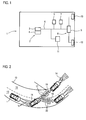
- Fig. 1 It shows a chassis control system, here an ESP system 2, which in the present case is arranged centrally in the motor vehicle 1 and comprises a control unit 3 and a sensor arrangement 4.
- the sensor arrangement 4 comprises acceleration sensors, rotation rate sensors and a lateral acceleration sensor. Data with other vehicle systems, for example a steering angle sensor 5, can be exchanged via a bus system 6, here a CAN bus.
- the control unit 3 determines a deviation between the driver's intention to move and the actual movement of the motor vehicle 1, for which particular parameters describing the driving dynamics of the motor vehicle 1 are determined.
- the target rotational rate is compared with the actual rotational rate.
- the ESP system 2 attempts by targeted braking individual wheels to prevent skidding of the motor vehicle 1 and the driver to secure control of the motor vehicle. For this purpose, it is communicated with a brake control unit 7. Outside the boundary region, ie when a spin state is detected, brake interventions are likewise made in order to stabilize the motor vehicle 1 again, which however is known and will not be described in detail here.
- the control unit 3 determines in the motor vehicle 1 according to the invention a stabilizing the motor vehicle direction of at least one driving dynamics descriptive, determined by the chassis control system 2 parameters. In this determined direction of travel now the driver's gaze is to be steered to achieve a correct, the motor vehicle 1 stabilizing countersteering in this.
- the motor vehicle 1 now further comprises a headlamp system 8.
- This comprises a control unit 9 controllable headlights 10, the illumination area is changeable, here by pivoting the headlamp 10 itself.
- an information system which in the present case comprises a contact-analogous head-up display 11 as a display device.
- the control unit 3 is now designed to control the headlight system 8 as a further vehicle system in such a way that the driving direction stabilizing the motor vehicle is illuminated, that is, the headlights 10 are pivoted so that they now shine in the direction of travel determined by the control unit 3. The driver will follow with his eyes the headlights and intuitively correct counter.
- the float angle determined in the control unit 3 can be taken into account, which indeed indicates how far the vehicle has deviated from the direction desired by the driver through the steering angle.
- the headlights 10 can now be pivoted against the deviation by the float angle to guide the driver back to its original desired direction of travel.
- the overall state of the motor vehicle described by the parameters describing the driving dynamics is considered and a most suitable driving direction is determined in order to stabilize the motor vehicle.
- the head-up display 11 can also be used. For example, by symbols or the like, the direction of travel on the windshield can be highlighted.
- Fig. 2 explains the operation of the method according to the invention for assisting the driver, as realized by the motor vehicle 1, closer. Shown is a road 12 with two lanes 13 and the motor vehicle 1 and the footprints of its headlights at different times. In addition, a tree 14 is located to the side of the roads. In the position A, the motor vehicle 1 passes through the curve. In position B, it has skidded, as shown by the arrow 15 (rotation about the vertical axis). If the motor vehicle were not configured to carry out the method according to the invention, the headlights 10 of the motor vehicle 1 would continue to illuminate in front of the motor vehicle 1, as shown by the illumination areas 16 in the position A, as shown in dashed lines as illumination areas 17 in position B. is. The driver looks forward to the tree 14 as indicated by the arrow 18, and would continue to unconsciously lean on it, as indicated by the position C.
- the motor vehicle 1 stabilizing direction of travel 19 is determined and the headlights 10 accordingly in this direction, for example, by pivoting about the slip angle, as shown by the footprints 20.
- the driver now follows his view with the headlights and thus steers intuitively back: The vehicle thus returns to the correct lane 13, position D.
- a possible collision with the tree 14 can be avoided and the driver is supported, the motor vehicle. 1 to stabilize again.
- Fig. 3 finally shows a possible display on the head-up display 11, so information that are projected analogous to the windshield 21.
- the road 12 and the tree 14 can be seen when the motor vehicle 1 in the position B in Fig. 2 located. Also visible are the footprints 20 that illuminate the headlights 10 according to the direction of travel 19 stabilizing the motor vehicle.
- orientation arrows 22 for the driver are now projected onto the windshield by the contact-analogous head-up display in order to further assist him in countersteering.
- the ESP system 2 continues to carry out its usual measures for stabilizing the motor vehicle 1 in the motor vehicle 1 according to the invention. At the same time, however, the driver is given an indication of how he can support the stabilization process and return to his original path.
Landscapes
- Engineering & Computer Science (AREA)
- Mechanical Engineering (AREA)
- Transportation (AREA)
- Chemical & Material Sciences (AREA)
- Combustion & Propulsion (AREA)
- Automation & Control Theory (AREA)
- Human Computer Interaction (AREA)
- Lighting Device Outwards From Vehicle And Optical Signal (AREA)
- Regulating Braking Force (AREA)
Applications Claiming Priority (1)
| Application Number | Priority Date | Filing Date | Title |
|---|---|---|---|
| DE102009035634A DE102009035634B4 (de) | 2009-07-31 | 2009-07-31 | Verfahren zur Unterstützung eines Fahrers eines Kraftfahrzeugs während eines Schleudervorgangs und entsprechendes Kraftfahrzeug |
Publications (2)
| Publication Number | Publication Date |
|---|---|
| EP2279923A2 true EP2279923A2 (fr) | 2011-02-02 |
| EP2279923A3 EP2279923A3 (fr) | 2013-12-25 |
Family
ID=42990304
Family Applications (1)
| Application Number | Title | Priority Date | Filing Date |
|---|---|---|---|
| EP10006863.4A Withdrawn EP2279923A3 (fr) | 2009-07-31 | 2010-07-02 | Procédé d'assistance au conducteur d'un véhicule automobile lors d'un procédé de propulsion et véhicule automobile |
Country Status (2)
| Country | Link |
|---|---|
| EP (1) | EP2279923A3 (fr) |
| DE (1) | DE102009035634B4 (fr) |
Cited By (4)
| Publication number | Priority date | Publication date | Assignee | Title |
|---|---|---|---|---|
| CN102951072A (zh) * | 2011-08-23 | 2013-03-06 | 罗伯特·博世有限公司 | 用于匹配车辆的至少一个大灯的光发射的方法和设备 |
| CN108549880A (zh) * | 2018-04-28 | 2018-09-18 | 深圳市商汤科技有限公司 | 碰撞控制方法及装置、电子设备和存储介质 |
| CN111002997A (zh) * | 2019-12-06 | 2020-04-14 | 武汉中海庭数据技术有限公司 | 一种偏离车道提示方法及装置 |
| DE102021115662B3 (de) | 2021-06-17 | 2022-08-25 | Audi Aktiengesellschaft | Verfahren zur Unterstützung eines Fahrers eines Kraftfahrzeugs während eines Brems- und/oder Schleudervorgangs auf losem Untergrund und Kraftfahrzeug |
Families Citing this family (3)
| Publication number | Priority date | Publication date | Assignee | Title |
|---|---|---|---|---|
| DE102013225674C5 (de) | 2013-12-11 | 2018-12-13 | Bombardier Transportation Gmbh | Verfahren zur Darstellung von Informationen für Verkehrsteilnehmer über den Betrieb eines Schienenfahrzeugs |
| DE102016001125B4 (de) | 2016-02-02 | 2025-01-23 | Audi Ag | Verfahren zum Betrieb eines Fahrerassistenzsystems zum Unterstützen eines Fahrers bei einem Schleudervorgang und Kraftfahrzeug |
| DE102023124352B3 (de) * | 2023-09-11 | 2024-09-12 | Dr. Ing. H.C. F. Porsche Aktiengesellschaft | Verfahren zum Anpassen einer von einem Scheinwerfersystem eines Fahrzeugs erzeugten Lichtverteilung an eine Fahrsituation |
Citations (2)
| Publication number | Priority date | Publication date | Assignee | Title |
|---|---|---|---|---|
| DE10141425A1 (de) | 2001-08-23 | 2003-03-13 | Daimler Chrysler Ag | Verfahren zur fahrzustandsabhängigen Lenkunterstützung |
| DE10354662A1 (de) | 2003-11-22 | 2005-06-23 | Robert Bosch Gmbh | Verfahren zum Unterstützen des Fahrers in fahrdynamischen Grenzsituationen durch Aufbringen eines Lenkmoments |
Family Cites Families (9)
| Publication number | Priority date | Publication date | Assignee | Title |
|---|---|---|---|---|
| DE19738765B4 (de) * | 1997-09-04 | 2008-11-27 | Bayerische Motoren Werke Aktiengesellschaft | Vorrichtung zur Anzeige der momentanen Fahrtrichtung eines Fahrzeugs |
| DE19839198B4 (de) * | 1998-08-28 | 2004-08-12 | Robert Bosch Gmbh | Verfahren zum Anzeigen von Fahrerinformationen in einem Kraftfahrzeug |
| US6626563B2 (en) * | 2000-10-03 | 2003-09-30 | Denso Corporation | Automatic optical-axis adjusting device for automatically adjusting optical axes of front lights of vehicle with reduced number of signals |
| ATE552478T1 (de) * | 2004-06-03 | 2012-04-15 | Making Virtual Solid L L C | Navigationsanzeigeverfahren und vorrichtung für unterwegs unter verwendung eines head-up-displays |
| DE102004060880B4 (de) * | 2004-12-17 | 2017-07-13 | Volkswagen Ag | Verfahren und Vorrichtung zum Steuern eines Fahrzeugscheinwerfers |
| DE102005055744A1 (de) * | 2005-11-23 | 2007-05-24 | Robert Bosch Gmbh | Fahrerassistenzsystem für Kraftfahrzeuge |
| DE102006036361A1 (de) * | 2006-08-02 | 2008-02-07 | GM Global Technology Operations, Inc., Detroit | Scheinwerfer in einem Kraftfahrzeug |
| DE102006047092B4 (de) * | 2006-10-05 | 2011-07-14 | Audi Ag, 85057 | Verfahren zur Unterstützung der Blickführung eines Fahrers eines Fahrzeugs und Fahrerassistenzsystem |
| DE102007058295A1 (de) * | 2007-12-05 | 2009-06-10 | Audi Ag | Anzeigeeinrichtung für Kraftfahrzeug |
-
2009
- 2009-07-31 DE DE102009035634A patent/DE102009035634B4/de not_active Expired - Fee Related
-
2010
- 2010-07-02 EP EP10006863.4A patent/EP2279923A3/fr not_active Withdrawn
Patent Citations (2)
| Publication number | Priority date | Publication date | Assignee | Title |
|---|---|---|---|---|
| DE10141425A1 (de) | 2001-08-23 | 2003-03-13 | Daimler Chrysler Ag | Verfahren zur fahrzustandsabhängigen Lenkunterstützung |
| DE10354662A1 (de) | 2003-11-22 | 2005-06-23 | Robert Bosch Gmbh | Verfahren zum Unterstützen des Fahrers in fahrdynamischen Grenzsituationen durch Aufbringen eines Lenkmoments |
Cited By (8)
| Publication number | Priority date | Publication date | Assignee | Title |
|---|---|---|---|---|
| CN102951072A (zh) * | 2011-08-23 | 2013-03-06 | 罗伯特·博世有限公司 | 用于匹配车辆的至少一个大灯的光发射的方法和设备 |
| EP2562043A3 (fr) * | 2011-08-23 | 2014-01-22 | Robert Bosch Gmbh | Procédé et dispositif destinés à adapter le faisceau lumineux d'au moins un phare de véhicule |
| US9067534B2 (en) | 2011-08-23 | 2015-06-30 | Robert Bosch Gmbh | Method and device for adjusting a light emission of at least one headlight of a vehicle |
| CN102951072B (zh) * | 2011-08-23 | 2017-05-03 | 罗伯特·博世有限公司 | 用于匹配车辆的至少一个大灯的光发射的方法和设备 |
| CN108549880A (zh) * | 2018-04-28 | 2018-09-18 | 深圳市商汤科技有限公司 | 碰撞控制方法及装置、电子设备和存储介质 |
| CN108549880B (zh) * | 2018-04-28 | 2021-06-25 | 深圳市商汤科技有限公司 | 碰撞控制方法及装置、电子设备和存储介质 |
| CN111002997A (zh) * | 2019-12-06 | 2020-04-14 | 武汉中海庭数据技术有限公司 | 一种偏离车道提示方法及装置 |
| DE102021115662B3 (de) | 2021-06-17 | 2022-08-25 | Audi Aktiengesellschaft | Verfahren zur Unterstützung eines Fahrers eines Kraftfahrzeugs während eines Brems- und/oder Schleudervorgangs auf losem Untergrund und Kraftfahrzeug |
Also Published As
| Publication number | Publication date |
|---|---|
| EP2279923A3 (fr) | 2013-12-25 |
| DE102009035634B4 (de) | 2012-06-28 |
| DE102009035634A1 (de) | 2011-02-17 |
Similar Documents
| Publication | Publication Date | Title |
|---|---|---|
| EP3554907B1 (fr) | Procédé de régulation automatique de la vitesse d'une motocyclette | |
| DE102005004394B4 (de) | Rückfahrtassistent | |
| DE102012203228B4 (de) | Verfahren zur Vermeidung oder zur Abschwächung von Folgen bei Kollisionen eines Kraftfahrzeugs mit einem Hindernis in einem seitlichen Nahbereich des Kraftfahrzeugs und Fahrassistenzsystem | |
| DE102011116822B4 (de) | Überwachungssystem zur Überwachung des Umfeldes von Fahrzeugen, insbesondere von Kraft- und/oder Nutzfahrzeugen | |
| DE102009035634B4 (de) | Verfahren zur Unterstützung eines Fahrers eines Kraftfahrzeugs während eines Schleudervorgangs und entsprechendes Kraftfahrzeug | |
| EP2170679A1 (fr) | Système d'assistance à la manoeuvre de stationnement et procédé pour faciliter une manoeuvre de sortie de stationnement | |
| EP3956167B1 (fr) | Procédé d'exécution d'une correction de la direction de déplacement par un système d'aide à la conduite dans un véhicule à moteur ainsi que dispositif de commande à cet effet | |
| DE102015011231B4 (de) | Verfahren zum Betrieb einer in einem Kraftfahrzeug angeordneten Laserheckleuchte, Laserheckleuchte und Kraftfahrzeug | |
| EP2583875A2 (fr) | Procédé et dispositif de réglage de l'assistance de maintien de la trajectoire | |
| DE102007029909A1 (de) | Verfahren zum automatischen Korrigieren einer Zustandsgröße eines Fahrzeugs | |
| WO2010089240A1 (fr) | Procédé et dispositif de mise en oeuvre d'une manoeuvre d'évitement | |
| DE102012214829A1 (de) | Verfahren und Vorrichtung zum Darstellen einer Ausweichtrajektorie zur Kollisionsvermeidung für ein Fahrzeug | |
| DE102011085140A1 (de) | Verfahren und Steuergerät zum Betreiben einer Fahrdynamikregelung eines Fahrzeugs sowie Regelsystem zur Fahrdynamikregelung eines Fahrzeugs unter Verwendung von Umfeldsensorikdaten | |
| WO2005047045A1 (fr) | Systeme de controle de trajectoire actif | |
| DE102011081412B4 (de) | Verfahren und Vorrichtung zur Anpassung einer Lichtaussendung von zumindest einem Scheinwerfer eines Fahrzeugs | |
| EP3401157A1 (fr) | Procédé de réglage du sillage d'une deux roues, appareil de commande et deux roues | |
| DE102013010306A1 (de) | Verfahren zum Betrieb einer Hinterachslenkung eines Fahrzeugs | |
| DE102021207879A1 (de) | Verfahren zur Anpassung wenigstens einer Lenkcharakteristik eines Lenksystems | |
| DE102023002351A1 (de) | Verfahren zur Durchführung einer prädiktiven Lenksteuerung sowie Steer-by-Wire-Lenksystem | |
| DE102016208604A1 (de) | Verfahren und Vorrichtung zur Durchführung eines Ausweichmanövers für ein Kraftfahrzeug | |
| DE102010054355A1 (de) | Verfahren und Vorrichtung zur Unterstützung eines Fahrers bei der Stabilisierung und Spurhaltung eines Fahrzeugs nach einem Ausweichmanöver | |
| DE102019204565B4 (de) | Verfahren zum Manövrieren eines Fahrzeugs | |
| DE102019204102A1 (de) | Verfahren und Fahrerassistenzsystem zum Unterstützen eines Fahrers eines Fahrzeugs beim Einparken in eine Längsparklücke | |
| DE102011010370A1 (de) | Verfahren und Vorrichtung zur Unterstützung des Fahrers eines Fahrzeugs mit Allradlenkung bei einem Einparkvorgang in eine Längsparklücke oder Ausparkvorgang aus einer Längsparklücke | |
| WO2022238219A1 (fr) | Procédé de fonctionnement d'un système d'assistance au changement de voie d'un véhicule, avec différenciation en fonction de la vitesse d'un signal de clignotant subséquent, système d'assistance au changement de voie et véhicule |
Legal Events
| Date | Code | Title | Description |
|---|---|---|---|
| PUAI | Public reference made under article 153(3) epc to a published international application that has entered the european phase |
Free format text: ORIGINAL CODE: 0009012 |
|
| AK | Designated contracting states |
Kind code of ref document: A2 Designated state(s): AL AT BE BG CH CY CZ DE DK EE ES FI FR GB GR HR HU IE IS IT LI LT LU LV MC MK MT NL NO PL PT RO SE SI SK SM TR |
|
| AX | Request for extension of the european patent |
Extension state: BA ME RS |
|
| PUAL | Search report despatched |
Free format text: ORIGINAL CODE: 0009013 |
|
| AK | Designated contracting states |
Kind code of ref document: A3 Designated state(s): AL AT BE BG CH CY CZ DE DK EE ES FI FR GB GR HR HU IE IS IT LI LT LU LV MC MK MT NL NO PL PT RO SE SI SK SM TR |
|
| AX | Request for extension of the european patent |
Extension state: BA ME RS |
|
| RIC1 | Information provided on ipc code assigned before grant |
Ipc: B62D 15/02 20060101ALI20131119BHEP Ipc: B60W 30/02 20120101AFI20131119BHEP |
|
| 17P | Request for examination filed |
Effective date: 20140625 |
|
| RBV | Designated contracting states (corrected) |
Designated state(s): AL AT BE BG CH CY CZ DE DK EE ES FI FR GB GR HR HU IE IS IT LI LT LU LV MC MK MT NL NO PL PT RO SE SI SK SM TR |
|
| STAA | Information on the status of an ep patent application or granted ep patent |
Free format text: STATUS: THE APPLICATION HAS BEEN WITHDRAWN |
|
| 18W | Application withdrawn |
Effective date: 20160311 |