EP2280112A1 - Waschmaschine und Filteranordnung für den Entleerungskreis einer Waschmaschine - Google Patents
Waschmaschine und Filteranordnung für den Entleerungskreis einer Waschmaschine Download PDFInfo
- Publication number
- EP2280112A1 EP2280112A1 EP09009687A EP09009687A EP2280112A1 EP 2280112 A1 EP2280112 A1 EP 2280112A1 EP 09009687 A EP09009687 A EP 09009687A EP 09009687 A EP09009687 A EP 09009687A EP 2280112 A1 EP2280112 A1 EP 2280112A1
- Authority
- EP
- European Patent Office
- Prior art keywords
- cup
- shaped body
- hollow container
- closed hollow
- draining
- Prior art date
- Legal status (The legal status is an assumption and is not a legal conclusion. Google has not performed a legal analysis and makes no representation as to the accuracy of the status listed.)
- Withdrawn
Links
- 238000001914 filtration Methods 0.000 title claims abstract description 80
- 238000010412 laundry washing Methods 0.000 title claims abstract description 33
- 238000005406 washing Methods 0.000 claims abstract description 195
- 239000007788 liquid Substances 0.000 claims abstract description 54
- 230000002093 peripheral effect Effects 0.000 claims abstract description 34
- 238000000638 solvent extraction Methods 0.000 claims description 3
- 210000002105 tongue Anatomy 0.000 description 19
- 238000010276 construction Methods 0.000 description 8
- 238000003780 insertion Methods 0.000 description 6
- 230000037431 insertion Effects 0.000 description 6
- 239000002351 wastewater Substances 0.000 description 5
- 230000005484 gravity Effects 0.000 description 4
- 230000003134 recirculating effect Effects 0.000 description 4
- XLYOFNOQVPJJNP-UHFFFAOYSA-N water Substances O XLYOFNOQVPJJNP-UHFFFAOYSA-N 0.000 description 4
- 238000004140 cleaning Methods 0.000 description 3
- 239000003599 detergent Substances 0.000 description 3
- 239000002184 metal Substances 0.000 description 3
- 230000001419 dependent effect Effects 0.000 description 2
- 230000009191 jumping Effects 0.000 description 2
- 239000000463 material Substances 0.000 description 2
- 230000004048 modification Effects 0.000 description 2
- 238000012986 modification Methods 0.000 description 2
- 230000000284 resting effect Effects 0.000 description 2
- 238000003756 stirring Methods 0.000 description 2
- 239000000725 suspension Substances 0.000 description 2
- 238000011144 upstream manufacturing Methods 0.000 description 2
- 238000009736 wetting Methods 0.000 description 2
- 239000006096 absorbing agent Substances 0.000 description 1
- 238000001035 drying Methods 0.000 description 1
- 230000000694 effects Effects 0.000 description 1
- 238000010438 heat treatment Methods 0.000 description 1
- 238000009987 spinning Methods 0.000 description 1
- 239000008399 tap water Substances 0.000 description 1
- 235000020679 tap water Nutrition 0.000 description 1
Images

Classifications
-
- D—TEXTILES; PAPER
- D06—TREATMENT OF TEXTILES OR THE LIKE; LAUNDERING; FLEXIBLE MATERIALS NOT OTHERWISE PROVIDED FOR
- D06F—LAUNDERING, DRYING, IRONING, PRESSING OR FOLDING TEXTILE ARTICLES
- D06F39/00—Details of washing machines not specific to a single type of machines covered by groups D06F9/00 - D06F27/00
- D06F39/10—Filtering arrangements
Definitions
- the present invention relates to a laundry washing machine and to a filtering assembly for the draining circuit of a laundry washing machine.
- washing machine may as well indicate both a “simple” washing machine (i.e. a washing machine which can only wash and rinse the laundry) and a washing-drying machine (i.e. a washing machine which can also dry the laundry).
- front-loading laundry washing machines generally comprise a substantially parallelepiped-shaped outer box casing structured for resting on the floor; a substantially bell-shaped washing tub which is suspended in floating manner inside the casing by means of a number of coil springs and shock-absorbers, directly facing a laundry loading and unloading opening realized in the front face of the casing; a door hinged to the front face of the casing to rotate to and from a closing position in which the door closes the opening in the front face of the casing to seal the washing tub; a substantially bell-shaped cylindrical rotatable drum for housing the laundry to be washed, and which is housed substantially horizontally inside the washing tub to rotate about its longitudinal axis; and an electric motor assembly for rotating the drum about its longitudinal axis inside the washing tub.
- Laundry washing machines of the above type are also provided with a draining circuit adapted to drain the washing/rinsing liquid (i.e. water or water mixed with washing and/or rinsing products) from the bottom of the tub, particularly after the washing and rinsing phases, and to release it into a waste-water exhaust duct located outside of the washing machine casing.
- a draining circuit adapted to drain the washing/rinsing liquid (i.e. water or water mixed with washing and/or rinsing products) from the bottom of the tub, particularly after the washing and rinsing phases, and to release it into a waste-water exhaust duct located outside of the washing machine casing.
- the draining circuit comprises a draining sump obtained in the lower region of the lateral surface of the tub and fluidly communicating with the internal of the latter, so as to collect the washing/rinsing liquid present in the bottom of the tub; the draining sump fluidly communicates also with a draining pump, fluidly connected with one or more draining pipes adapted to drain to the waste-water exhaust duct the washing/rinsing liquid collected into the draining sump and sucked by the draining pump.
- the draining circuit is also provided with a recirculation circuit, adapted to drain the washing/rinsing liquid from the bottom of the tub and to re-admit such liquid into an upper region of the tub, for improving the wetting of the laundry.
- the draining circuit of these known washing machines also comprises a filtering assembly which is generally located into the draining sump, between the bottom of the tub and the drain pump.
- This filtering assembly comprises a cup-shaped basket, having perforated walls, which is snap-fitted in a stable, but easy removable manner into the draining sump; the cup-shaped basket collects and retains lint, fluff, and all undesirable bodies (for example, buttons came off from the laundry, coins or rings erroneously introduced into the washing machine, etc.) passed through the holes located on the periphery of the washing drum, or fell to the bottom of the tub by passing between the drum and the tub, which could damage or obstruct the draining pump.
- the cup-shaped basket having perforated walls, which is snap-fitted in a stable, but easy removable manner into the draining sump; the cup-shaped basket collects and retains lint, fluff, and all undesirable bodies (for example, buttons came off from the laundry, coins or rings erroneously introduced into the washing machine, etc.) passed through the holes located on the periphery of the washing drum, or fell to the bottom of the tub by passing between the drum and the
- a user may reach the filtering assembly, for example for its removal and/or cleaning, directly from the internal of the drum, typically via a suitable opening, obtained in the lateral surface of the drum, which is closable by a removable lifter (i.e. an element fixed to the inner lateral surface of the drum adapted to improve the stirring of the laundry during the rotation of the latter) or by another suitable lid associated to the inner lateral surface of the drum.
- a removable lifter i.e. an element fixed to the inner lateral surface of the drum adapted to improve the stirring of the laundry during the rotation of the latter
- another suitable lid associated to the inner lateral surface of the drum.
- EP 1 849 904 discloses a top-loading washing machine comprising a draining filter access apparatus integrated in a lifter diametrically opposite to the drum access door (i.e. to the internal lid allowing the access to the drum).
- the draining filter access apparatus comprises a body, including an opening aligned with an opening of the same shape and dimensions made in the body of the drum, and a lid, hinged to the body and locking on the body by a simple ratchet mechanism.
- the major drawback of this type of known filtering assembly is that, particularly during the spinning phase, coins, rings, buttons and similar small objects start hopping around inside the cup-shaped basket due to the hard mechanical vibrations of the washing tub, and may jump out of the cup-shaped body. If magnitude of vibrations is enough strong, the objects jumping out of the cup-shaped body may also reach the peripheral wall of the drum and, if drum is rotating at high speed, these objects may be shot by the drum against the washing tub at very high speed. Particularly in case of coins, rings and other metal objects, the consequent heavy impact against the washing tub is extremely noisy and it may also damage the washing tub and create leaks.
- Another object of the invention is to allow a user to easily remove coins, rings, buttons and similar small objects from the internal of the filtering assembly.
- Another object of the present invention is to facilitate the correct insertion and fixation of the filtering assembly into the draining sump of a washing machine.
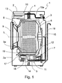
- number 1 indicates as a whole a laundry washing machine which comprises: a preferably, though not necessarily, parallelepiped-shaped outer box casing 2 structured for resting on the floor; a substantially bell-shaped washing tub 3 suspended in floating manner inside casing 2, advantageously via a suspension system comprising a number of coil springs 4 (only one shown in Figure 1 ) preferably, though not necessarily, combined with one or more vibration dampers 5 (only one shown in Figure 1 ); a substantially bell-shaped cylindrical rotatable drum 6 for housing the laundry to be washed, and which is fixed in axially rotating manner inside washing tub 3 for rotating about its longitudinal axis L; and an electric motor 7 for rotating, on command, drum 6 about its longitudinal axis "L" inside washing tub 3.
- the electric motor 7 may be connected to the drum 6 via a suitable belt pulley, as illustrated in Figure 1 , or it may be also directly mounted on the drum 6 (or on a rotating shaft associated to the drum 6).
- drum 6 is housed into washing tub 3 so that its longitudinal axis "L” is oriented substantially horizontally, and approximately coincides with the longitudinal axis of washing tub 3. Together with washing tub 3, drum 6 forms the washing group of the washing machine.
- the longitudinal axis "L” of the drum 6, and also the approximately coinciding longitudinal axis of the washing tub 3, may be also inclined.
- the laundry washing machine 1 is a front-loading washing machine, and therefore washing tub 3 is suspended substantially horizontally inside casing 2, with the front opening of washing tub 3 directly faced to a laundry loading and unloading opening formed in the front face 2a of casing 2.
- the laundry washing machine 1 is provided with a cylindrical elastic-deformable bellows 8 which connects the front opening of washing tub 3 to the laundry loading and unloading opening formed in the front face 2a of casing 2.
- Laundry washing machine 1 also comprises a porthole door 9 which is hinged to front face 2a of casing 2 to rotate to and from a closing position in which porthole door 9 closes the laundry loading and unloading opening in front face 2a to watertight seal the washing tub 3.
- laundry washing machine 1 is also provided with a washing/rinsing liquid (i.e. water or water mixed with washing and/or rinsing products) supply circuit 10 for supplying, on command, a given amount of washing/rinsing liquid into washing tub 3.
- a washing/rinsing liquid i.e. water or water mixed with washing and/or rinsing products
- the washing/rinsing liquid supply circuit 10 advantageously comprises a detergent drawer 13, fluidly connected to the washing tub 3, which is removably housed inside a seat provided on the front face 2a of casing 2, and which has at least one compartment for a given amount of a washing and/or rinsing product (for example a detergent and/or a softener) for use in the washing cycle.
- the washing/rinsing liquid supply circuit 10 also comprises one or more pipes or ducts 10a adapted for feeding, on command, a given amount of tap water into the compartments of drawer 13, so as to flush the washing and/or rinsing products out of the compartments and down into the washing tub 3.
- Laundry washing machine 1 also comprises a draining circuit 11 adapted to drain, after the washing and the rinsing phases, the washing/rinsing liquid accumulated on the bottom of washing tub 3 into a waste-water exhaust duct (non shown) located outside of the casing 2.
- the draining sump 17 is obtained in single-body construction with the washing tub 3.
- the draining circuit comprises a draining pump 18, fluidly connected to the draining sump 17, which impeller chamber 18a is preferably, but not necessarily, obtained in a single-piece construction with the draining sump 17 and with the washing tub 3, preferably in correspondence to an extension of the draining sump 17.
- the draining pump 18 is housed preferably into a suitable housing, not illustrated, obtained preferably, but not necessarily, in an extension of the draining sump 17, preferably in a single-piece construction with the latter.
- the draining pump 18 is also fluidly connected to a draining pipe 16 which fluidly connects the outlet of the draining pump 18 to the waste-water exhaust duct (not shown) located outside of casing 2.
- the draining circuit may be also provided with a recirculation circuit, adapted to drain the washing/rinsing liquid from the bottom of the washing tub 3 and to re-admit such liquid into an upper or central region of the washing tub 3 or directly into the drum 6, for improving the wetting of the laundry.
- a recirculation circuit adapted to drain the washing/rinsing liquid from the bottom of the washing tub 3 and to re-admit such liquid into an upper or central region of the washing tub 3 or directly into the drum 6, for improving the wetting of the laundry.
- the recirculation circuit comprises a recirculating pipe 15 which connects, preferably via a tree-way valve 14, the draining pump 18 to the drum 6 (but clearly the recirculating pipe may connect the draining pump 18 to an upper portion of washing tub 3), so that the draining pump 18 (depending on the status of the three-way valve 14) may re-admit into a central region of the drum 6 (or in an upper or central region of the washing tub 3) the washing/rinsing liquid exiting the washing tub 3 via the draining sump 17.
- the recirculation circuit comprises a dedicated recirculation pump, also not illustrated, fluidly connected downstream of the draining sump 17 and housed preferably into a suitable further housing obtained preferably in a further extension of the draining sump 17; the recirculation pump is in this case fluidly connected to a recirculating pipe 15 which connects the recirculation pump to the upper portion of washing tub 3 (or directly to drum 6).
- the further housing is obtained in a single-piece construction with the draining sump 17 and with the washing tub 3.
- the impeller chamber of the recirculation pump may be obtained in a single-piece construction with the draining sump 17 and with the washing tub 3.
- the recirculation pump sucks the washing/rinsing liquid from the bottom of the washing tub 3 via the draining sump 17, and re-admits such liquid into an upper or central region of the washing tub 3 or drum 6 via the recirculating pipe 15.
- recirculation circuit may be also not provided.
- washing/rinsing liquid may exit the washing tub only via the draining sump 17.
- Laundry washing machine 1 also comprises an electrically operated heater 12, namely a resistor, which is located on the bottom of washing tub 3, preferably, thought not necessarily, into an outwards-projecting recessed seat 3a realized on the bottom of washing tub 3, and is structured for rapidly heating the washing/ rinsing liquid accumulated on the bottom of washing tub 3.
- an electrically operated heater 12 namely a resistor, which is located on the bottom of washing tub 3, preferably, thought not necessarily, into an outwards-projecting recessed seat 3a realized on the bottom of washing tub 3, and is structured for rapidly heating the washing/ rinsing liquid accumulated on the bottom of washing tub 3.
- washing tub 3 washing tub 3, the suspension system, drum 6, electric motor assembly 7, bellows 8, porthole door 9, the washing/rinsing liquid supply circuit 10 and the heater 12 are commonly know parts in the washing machine technical field, and therefore not described in detail.
- the draining circuit 11 is provided with a washing/ rinsing liquid filtering assembly 19 which is housed, preferably, but not necessarily in a removable way, into the draining sump 17, upstream of draining pump 18 (and therefore also upstream of the further recirculation pump if the latter is provided), and is structured for allowing the free passage of the washing/rinsing liquid, and for holding fluff, lint and all the other undesirable bodies (for example, buttons came off from the laundry, coins or rings erroneously introduced into the washing machine, etc.) present in the washing/ rinsing liquid.
- a washing/ rinsing liquid filtering assembly 19 which is housed, preferably, but not necessarily in a removable way, into the draining sump 17, upstream of draining pump 18 (and therefore also upstream of the further recirculation pump if the latter is provided), and is structured for allowing the free passage of the washing/rinsing liquid, and for holding fluff, lint and all the other undesirable bodies
- This filtering assembly 19 is arranged in such a way that it completely obstructs the draining sump 17, and therefore the washing/rinsing liquid has to pass necessarily through this filtering assembly 19 before exiting the washing tub 3 via the draining sump 17 and going to the draining circuit and/or to the recirculation circuit (clearly if the latter is provided); fluff, lint, conins, buttons, rings, and all the other undesirable bodies contained in the washing/rinsing liquid are therefore trapped by the filtering assembly 19 before exiting the draining sump 17.
- the removal of the filtering assembly 19 from the working position in which the filtering assembly 19 is housed into the draining sump 17 can be performed manually by the user, directly from the internal of the drum 6, through an opening 6a provided on the peripheral wall of drum 6; this opening 6a may be closed, for example, by a lifter or elevator 6b, removably associated to the peripheral wall of drum 6 and adapted to improve the stirring of the laundry during the rotation of the drum 6.
- the opening 6a may be removably closed by a dedicated lid, not illustrated.
- the filtering assembly 19 comprises a closed hollow container 19, at least part of which external surface comprises a plurality of apertures or holes 30 adapted to allow the free passage of the washing/rinsing liquid, and to impede the passage of fluff, lint and other undesirable bodies (i.e. buttons, coins, rings, etc.) present in the washing/rinsing liquid.
- the closed hollow container 19 is structured for being openable by a user, in order to allow a user to accede to its internal, for example for removing lint, fluff, coins, buttons, rings, or other undesirable bodies therein accumulated.
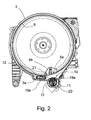
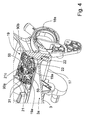
- the closed hollow container 19 is provided with one or more transversal long and narrow slots 19a dimensioned for permitting the entrance of coins, rings, buttons and similar small objects into the container (clearly also washing/rinsing liquid and fluff or lint may enter the closed hollow container 19 via the one or more slots 19a); advantageously the closed hollow container 19 is arranged in such a way that when it is correctly positioned into the draining sump 17, in an operative position, illustrated in Figure 4 , the one or more slots 19a are located inside the washing tub 3, and extends locally substantially tangent to the bottom surface of washing tub 3.
- the one or more slots 19a are substantially flush with the bottom surface of the washing tub 3; this, how will be better explained in the following, allows the entrance into the closed hollow container 19, through the one or more slots 19a, of coins, rings, buttons and similar objects laying on the bottom surface of the washing tub 3.
- closed hollow container 19 is fitted into draining sump 17 so that at least part of the one or more transversal slots 19a is oriented locally substantially perpendicular to the travelling direction, illustrated with an arrow indicated with letter "d" in Figure 3 , of the overhanging portion of peripheral wall of drum 6, so that coins, rings, buttons and similar small objects that reach the bottom of the washing tub 3 are swept away into slots 19a of the closed hollow container 19 by the washing/rinsing liquid which moves more or less tangentially to the bottom of washing tub 3 when drum 6 rotates about its longitudinal axis L.
- the travelling direction "d" of the overhanging portion of peripheral wall of drum 6 is, obviously, perpendicular to longitudinal axis "L" of drum 6.
- closed hollow container 19 is fitted into draining sump 17 so that at least part of the one or more transversal slots 19a crosses transversally the substantially cylindrical lateral surface of the washing drum 6.
- the draining sump 17 is preferably, thought not necessarily, placed on the bottom of the recessed seat 3a which houses the heater 12, beside the heater 12.
- the bottom surface of the recessed seat 3a (which in this case coincide with the bottom surface of the washing tub 3) is tilted towards the draining sump 17 and towards two slots 19a provided on one of the lateral walls (in particular the one indicated with number 40a in Figure 3 ) of the closed hollow container 19 fitted into the draining sump 17, so as to facilitate the sliding, by gravity, of coins, rings, buttons and similar small objects, laying on the bottom of the recessed seat 3a, into these slots 19a.
- the draining sump 17 may be positioned in another region of the bottom of the washing tub 3, and therefore also not in correspondence of the recessed seat 3a; in this case, not illustrated, the bottom surface of the washing tub 3 contiguous to one or both the lateral walls 40a, 40b of the draining sump 17 provided with the one or more slots 19a, may be tilted towards the latter, in order to facilitate the sliding, by gravity, into slots 19a, of coins, rings, buttons and similar small objects laying on this bottom surface.
- coins, rings, buttons and similar small objects laying on the bottom of the washing tub 3 are conveyed into the one or more slots 19a by gravity (thanks to the inclination of the bottom surface of the washing tub 3) and also, during the washing, by the rotation of the drum 6 which moves the washing/rinsing liquid more or less tangentially to the bottom of washing tub 3 (and therefore substantially along the travelling direction "d" of the overhanging portion of peripheral wall of drum 6), dragging in the same direction (and therefore towards one or more slots 19a) coins, rings, buttons and similar small objects laying on the bottom of the washing tub 3.
- the closed hollow container 19 comprises preferably, thought not necessarily, a cup-shaped body 20, on which external surface, preferably both on its lateral surface and on its bottom, apertures or holes 30 are provided, adapted for allowing the free passage of the washing/rinsing liquid, and to impede the passage of fluff, lint and other undesirable bodies (i.e. buttons, coins, rings, etc.) present in the washing/rinsing liquid.
- a cup-shaped body 20 on which external surface, preferably both on its lateral surface and on its bottom, apertures or holes 30 are provided, adapted for allowing the free passage of the washing/rinsing liquid, and to impede the passage of fluff, lint and other undesirable bodies (i.e. buttons, coins, rings, etc.) present in the washing/rinsing liquid.
- the cup-shaped body 20 comprises an outwards-projecting peripheral flange 20a, projecting from its upper border and adapted to be put in abutment against the border of washing tub 3 surrounding the draining sump 17, while the rest of the cup-shaped body 20 is positioned inside the draining sump 17, for avoiding that such cup-shaped body 20 would fall into the draining sump 17.
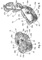
- the closed hollow container 19 illustrated in Figures 5 and 6 advantageously comprises an upper cover or lid 21 associated to the cup-shaped body 20 in a totally or partially removable way, so as to allow, by its full or partial removal, the access to the internal of the cup-shaped body 20.
- the upper cover or lid 21 is hinged to the cup-shaped body 20, preferably, but not necessarily to the outer peripheral flange 20a of the latter; in this case the upper cover or 21 may be manually rotated about the hinge articulation axis A, to from a closing position ( Figure 5 ) in which the upper cover or lid 21 lies above the opening of the cup-shaped body 20, with its peripheral edge 21a substantially parallel and spaced to the peripheral edge 20c of the cup-shaped body 20, so as to define a peripheral gap which is wide enough to permit the entrance into the cup-shaped body 20 of coins, rings, buttons and similar small objects.
- the peripheral gap defines the one or more transversal slots 19a of the closed hollow container 19.
- the slots 19a delimited by the cover or 21 and the cup-shaped body 20 are preferably, though not necessarily, 1-15 millimeters wide.
- the closed hollow container 19 also comprises manually-releasable locking means 22 structured for clamping in a rigid and stable, but easy releasable manner, the upper cover or lid 21 in the closing position to the cup-shaped body 20.
- locking means 22 consist preferably, though not necessarily, in one or more elastic-deformable snap-lock locking pins or tongues 22 projecting from both the outer peripheral flange 20a of cup-shaped body 20 and from the peripheral edge of lid 21, so as to selectively engage to one another.
- the cover or lid 21 may be associated to the cup-shaped body 20 in other suitable ways; for example the cover or lid 21 may be associated to the cup-shaped body 20 in a totally removable way, for instance by manually-releasable locking means, not illustrated.
- the cover or lid 21 independently from the way in which the cover or lid 21 is associated to the cup-shaped body 20, in the closing position the cover or lid 21 lies above the opening of the cup-shaped body 20 in such a way to define a peripheral gap which is wide enough to permit the entrance into the cup-shaped body 20 of coins, rings, buttons and similar small objects; the peripheral gap defines the one or more transversal slots 19a of the closed hollow container 19.
- the cover or lid 21 may be advantageously provided with a plurality of aperture or holes 31, dimensioned for permitting the free passage of the washing/rinsing liquid and of the fluff or lint, and to impede the passage of coins, rings, buttons and similar small objects; the aperture or holes 31 of the cover or lid 21 are therefore wider that the aperture or holes 30 of the cup-shaped body 20.
- the washing/rinsing liquid, and also the fluff or lint potentially present in the latter may therefore freely enter the cup-shaped body 20 both via the aperture or holes 31 of the cover or lid 21, and via the one or more transversal slots 19a.
- the cover or lid 21 isn't provided with holes or apertures; in this case washing/rinsing liquid may enter the cup-shaped body 20 via the one or more slots 19a; other openings, not illustrated, may be provided on the closed hollow container 19 for allowing washing/rinsing liquid, fluff, and lint, but not coins, rings, buttons and similar small objects, to enter the closed hollow container 19.
- Rings, buttons and similar small objects present in the bottom of the washing tub 3 enter the cup-shaped body 20 via the one or more slots 19a, by the effect of gravity and of the sloping of the bottom surface of the washing tub 3, and also, during the washing, by the rotation of the drum 6 which moves the washing/ rinsing liquid more or less tangentially to the bottom of washing tub 3, dragging in the same direction coins, rings, buttons and similar small objects laying on the bottom of the washing tub 3.
- buttons or other similar small objects have entered the cup-shaped body 20, and have settled in the bottom of the latter, they can't jump out of the cup-shaped body 20, because it is closed by the cover or lid 21.
- the removal of these rings, buttons or other similar small objects from the internal of the cup-shaped body 20 may be done by a user by lifting the cover or lid 21.
- buttons or other similar small objects have entered the closed hollow container 19 via the one or more slots 19a, they can't jump out of the closed hollow container 19, and they may be removed by a user, by opening the closed hollow container 19.
- the closed hollow container 19 preferably, though not necessarily, also comprises manually-releasable locking means 23 structured for clamping in a rigid and stable, but easy releasable manner, the cup-shaped body 20 to the body of the washing tub 3 when the closed hollow container 19 is fitted into the draining sump 17.
- locking means 23 comprise preferably, though not necessarily, a number of elastic-deformable snap-lock locking pins or tongues 23 projecting from the cup-shaped body 20, so as to selectively engage on the edge of the bottom wall of washing tub 3.
- the snap-lock locking pins or tongues 23 protrude laterally from two elastically deformable arms 50 provided respectively on the lateral walls 40a, 40b of the cup-shaped body 20 and arranged in such a way that they may be elastically pressed one towards the other, so as to cause the disengagement of the snap-lock locking pins or tongues 23 from the edge of the bottom wall of washing tub 3.
- the arms 50 are arranged in such a way that their free ends are accessible from the internal of the washing tub 3 when the filtering assembly 19 is inserted into the draining sump 17, so as to allow a user to press the arms 50 one towards the other for removing the filtering assembly 19 from the draining sump 17.
- the snap-lock locking pins or tongues 23 comprises a tilted surface 23a arranged so that it engages the edge of the bottom wall of washing tub 3 during the insertion of the cup-shaped body 20 into the latter, causing an elastic rotation of the respective arm 50 towards the inside of the cup-shaped body 20 while the latter is pushed towards the bottom of the draining sump 17, until the snap-lock locking pins or tongues 23 go beyond the edge of the bottom wall of washing tub 3, clasping the edge of the bottom wall of washing tub 3 between the snap-lock locking pins or tongues 23 and the peripheral flange 20a, and fixing in this way the closed hollow container 19 to the washing tub 3.
- cup-shaped body 20 and upper cover or lid 21 are preferably, thought not necessarily, made of plastic material, and locking means 22 and 23 are made in one piece respectively with the cup-shaped body 20 and with the upper lid 21.
- the cup-shaped body 20 is preferably, thought not necessarily, provided with a central septum 20b which lies substantially on the middle plane of the cup-shaped body 20 and of the closed hollow container 19 so as to divide the cup-shaped body 20 in two compartments, and which, preferably, but not necessarily, juts out from the opening of the cup-shaped body 20 substantially perpendicular to said opening.
- the central septum 20b is preferably partially perforated, in particular in proximity to the bottom of the cup-shaped body 20, and the closed hollow container 19 is fitted into the draining sump 17 so that the central septum 20b is locally substantially perpendicular to the bottom surface of washing tub 3 (or also, in the embodiment illustrated in Figure 3 , to the bottom surface of the recessed seat 3a on washing tub 3), and is oriented locally substantially perpendicular to the travelling direction "d" of the overhanging portion of peripheral wall of drum 6, so as to partly divert upwards the washing/rinsing liquid lapping against said bottom surface.
- the central septum 20b conveys the washing/rinsing liquid towards the bottom of the cup-shaped body 20, where the central septum 20b is partially perforated; the washing/rinsing liquid traverses therefore the central septum 20b in proximity of the bottom of the cup-shaped body 20, pushing in this way towards the internal of the washing tub 3 possible air bubbles which tend to accumulate on the bottom of the cup-shaped body 20, and which should compromise the correct functioning of the draining pump 18, or also damage the latter, if they would enter into the draining pump 18.
- the upper cover or lid 21 of the closed hollow container 19 is preferably, thought not necessarily, provided with a central septum 21 b which lies substantially on the middle plane of the upper cover or lid 21 and of the closed hollow container 19.
- the central septum 21b of upper cover or lid 21 is coplanar with the central septum 20b of the cup-shaped body 20, and is structured to fit and rest onto the upper edge of the central septum 20b of the cup-shaped body 20 when upper cover or lid 21 is placed in the closing position, so as to form, together with the central septum 20b, an inner partitioning wall of closed hollow container 19 which cuts in half the internal volume of closed hollow container 19.
- the hinge connecting upper cover or lid 21 to cup-shaped body 20 lies substantially on the middle plane of the closed hollow container 19, and the hinge articulation axis A is locally substantially perpendicular to said middle plane.
- the filtering assembly 19 may also be not provided with the central septum 21 b of upper cover or lid 21 and with the central septum 20b of the cup-shaped body 20.
- the filtering assembly 19 comprises at least one pushing support adapted for providing a stable support to the user, for facilitating the pushing of the filtering assembly 19 towards the bottom of the draining sump 17.
- the pushing support may comprise one or more regions (for example the regions numbered 90a and 90b in Figure 5 ) of the external surface of the closed hollow container 19 (particularly of the cover or lid 21 in the embodiment illustrated in Figure 6 ) opposite to the bottom of the draining sump 17 when the filtering assembly 19 is introduced into the latter, having an area wide enough to allow a user to place on one or more of his fingers, so as to easily push the closed hollow container 19 towards the bottom of the draining sump 17.
- the pushing support advantageously comprises a rigid base 21c protruding from the external surface of the cover or lid 21 opposite to the cup-shaped body 20; preferably but not necessarily, the rigid base 21c is located, approximately in the center of the outer face of the cover or lid 21, so as to be aligned to the central septum 21b which juts out from the inner face of the lid.
- the rigid base 21c is arranged in such a way that it is positioned between the two arms 50 when the upper cover or lid 21 is fixed to the cup-shaped body 20.
- the user can push directly on the rigid base 21c to drive, as a whole, the closed hollow container 19 into the draining sump 17, so as to cause the snap-lock locking pins or tongues 23 going beyond the edge of the bottom wall of washing tub 3, fixing the filtering assembly 19 into the draining sump 17.
- more than one rigid base 21c may be provided on the cover or lid 21.
- the at least one pushing support solves the technical problem of facilitating the correct insertion of the filtering assembly into the draining sump.
- the particular structure of the filtering assembly 19 has lots of advantages.
- the presence of the upper cover or lid 21 prevents coins, rings, buttons and similar small objects from jumping out of the cup-shaped body 20, particularly when drum 6 rotates at high speed and the whole washing group is subjected to hard mechanical vibrations.
- the closed hollow container 19 may consist of two valve-like half shells which are laterally hinged to one another, so as to be manually openable in a book-like manner when the closed hollow container 19 is completely extracted/removed from the draining sump 17 on the bottom wall of washing tub 3.
- the closed hollow container 19 is a closed box-shaped body, for example a cube, or a parallelepiped, or a prism, or a cylinder, on which lateral surface the one or more transversal long and narrow slots 19a are provided; in this case the internal of the closed hollow container 19 may be reached (for removing coins, buttons, rings or the like entered via the one or more slots 19a) via a suitable door or porthole provided on the external surface of such a box-shaped body.
- This door or porthole may be, for example, hinged to the external surface of the box-shaped body, or it may be slidably associated to the latter, for example by suitable guide, or it may be a sort of plug, partially or fully removable from the box-shaped body.
- laundry washing machine 1 may be as well a top-loading washing machine.
- the technical problem of avoiding that coins, rings, buttons and similar small objects collected into the filtering assembly would jump out of filtering assembling, particularly during the rotation of the drum, is solved also if the closed hollow container, openable by a user and provided with one or more slots 19a dimensioned for permitting the entrance of coins, rings, buttons and similar small objects into the container, is fixed to the draining sump 17 in a permanent (i.e. not-removable) way.
- a user my remove coins, buttons, rings, and other objects or material collected into the closed hollow container 19 by opening the latter, directly from the internal of the drum 6.
- the closed hollow container 19 may be advantageously obtained in a single-piece construction with the draining sump 17.
- the closed hollow container 19 comprises a cup-shaped body 20 and a cover or lid 21, for example analogous to the ones described above with reference to Figures 5 and 6
- the cup-shaped body 20 may be obtained in a single piece construction with the draining sump 17.
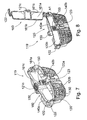
- a washing machine comprising a filtering assembly 119 comprising in turn a cup-shaped body 120, preferably substantially analogous to the cup-shaped body 20 illustrated with reference to the embodiment of Figures 1 to 6 , on which lateral wall and on which bottom apertures or holes 130 are provided, adapted to allow the free passage of washing/rinsing liquid, and to impede the passage of fluff, lint and other undesirable bodies (i.e. buttons, coins, rings, etc.) present in the washing/rinsing liquid.
- a filtering assembly 119 comprising in turn a cup-shaped body 120, preferably substantially analogous to the cup-shaped body 20 illustrated with reference to the embodiment of Figures 1 to 6 , on which lateral wall and on which bottom apertures or holes 130 are provided, adapted to allow the free passage of washing/rinsing liquid, and to impede the passage of fluff, lint and other undesirable bodies (i.e. buttons, coins, rings, etc.) present in the washing/rinsing liquid.
- the washing machine comprising the filtering assembly 119 may be both a top-loading washing machine and a front-loading washing machine (for example analogous to the one illustrated in Figures 1 , 2 , 3 and 4 ), provided that it comprises a washing tub, containing a drum, on which bottom surface a draining sump is provided, connected to a draining and/or recirculation circuit, into which the filtering assembly 119 may be removably fixed, so as to retain coins, rings, buttons and similar small objects present in the washing tub, for avoiding that these objects could reach the draining and/or the recirculation pump.
- the cup-shaped body 120 comprises manually-releasable locking means 123 structured for clamping in a rigid and stable, but easy releasable manner, the cup-shaped body 120 to the body of the washing tub when the cup-shaped body 120 is fitted into the draining sump.
- locking means 123 comprise, preferably though not necessarily, a number of elastic-deformable snap-lock locking pins or tongues 123 projecting from the cup-shaped body 120, so as to selectively engage on the edge of the bottom wall of the washing tub.
- the snap-lock locking pins or tongues 123 protrude laterally from two elastically deformable arms 150 provided respectively on the lateral walls 140a, 140b of the cup-shaped body 120 and arranged in such a way that they may be elastically pressed one towards the other, so as to cause the disengagement of the snap-lock locking pins or tongues 123 from the edge of the bottom wall of washing tub.
- the arms 150 are arranged in such a way that their free ends are accessible from the internal of the washing tub when the filtering assembly 119 is inserted into the draining sump, so as to allow a user to press the arms 150 one towards the other for removing the filtering assembly 119 from the draining sump.
- the snap-lock locking pins or tongues 123 comprises a tilted surface 123a arranged so that it engages the edge of the draining sump during the insertion of the cup-shaped body 120 into the latter, causing an elastic rotation of the respective arm 150 towards the inside of the cup-shaped body 120 while the latter is pushed towards the bottom of the draining sump, until the snap-lock locking pins or tongues 123 go beyond the edge of the bottom wall of washing tub 3, fixing the filtering assembly 119 to the washing tub in the same way described above with reference to the embodiment of figures 1 to 6 .
- the cup-shaped body 120 is advantageously provided with a central septum 120b which lies substantially on the middle plane of the cup-shaped body 120 so as to divide the cup-shaped body 120 in two compartments, and which, preferably, but not necessarily, juts out from the opening of the cup-shaped body 120 substantially perpendicular to said opening.
- the central septum 120b is arranged in such a way that, when the filtering assembly 119 is introduced into the sump, the central septum 120b is oriented locally substantially perpendicular to the travelling direction of the overhanging portion of peripheral wall of drum, so as to partly divert upwards the washing/rinsing liquid lapping against said bottom surface; the central septum 120b is preferably partially perforated, in particular in proximity to the bottom of the cup-shaped body 120, so as to allow the washing/rinsing liquid to remove possible air bubbles from the bottom of the cup shaped body 120, in the same way illustrated above with reference to the central septum 20b illustrated in Figures 3 and 5 .
- the filtering assembly 119 comprises at least one pushing support adapted for providing a stable support to the user for facilitating the pushing of the filtering assembly 119 towards the bottom of the draining sump.
- the pushing support comprises an upper member 160 associated, preferably in a totally or partially removable way, to the upper region of the cup-shaped body 120 facing the drum when the filtering assembly 119 is inserted into the sump.
- the upper member 160 comprises two substantially parallel plates 161a, 161b, connected one another in correspondence of one of their transversal end by a connecting element 161c, which may straddle the septum 120d of the cup-shaped body 120.
- the upper member 160 may be hinged to the cup-shaped body 120, preferably, but not necessarily to the outer peripheral flange 120a of the latter; in this case the upper member 160 may be manually rotated about the hinge articulation axis A1, to and from a closing position ( Figure 7 ) in which the upper member 160 straddle the septum 120d of the cup-shaped body 120.
- the filtering assembly 119 also comprises manually-releasable locking means 122 structured for clamping in a rigid and stable, but easy releasable manner, the upper member 160 in the closing position to the cup-shaped body 120.
- locking means 122 consist preferably, though not necessarily, in one or more elastic-deformable snap-lock locking pins or tongues 122 projecting from both an outer peripheral flange 120a of cup-shaped body 120 and from the peripheral edge of upper member 160, so as to selectively engage to one another.
- the upper member 160 may straddle the septum 120d of the cup-shaped body 120 in a fully removable way.
- the pushing support comprises also one or more rigid bases 121c, that is a rigid region having an area wide enough to allow a user to place thereon one or more of his fingers, so as to easily push the filtering assembly 119 towards the bottom of the draining sump.
- the pushing support comprises only one rigid base 121c, positioned in a central region of the connecting element 161c, so as to be placed between two arms 150 when the upper member 160 is in the closing position.
- the pushing support may comprise one or more regions of the upper member 160 which face the drum when the filtering assembly 119 is inserted into the sump and which have an area wide enough to allow a user to place on one or more of his fingers, so as to easily push the filtering assembly 119 towards the bottom of the draining sump.
- the upper member 160 is not provided, and one or more rigid bases 121c are provided directly on the central septum 120b; for example the one or more rigid bases 121c may be obtained in a single-body construction with the central septum 120b.
- a user may push directly on the one or more rigid bases 121c to drive the filtering assembly 119 into the draining sump 17, so as to cause the snap-lock locking pins or tongues 123 going beyond the edge of the bottom wall of washing tub and clasping the edge of the bottom wall of washing tub, so as to fix the filtering assembly 119 into the draining sump.
- a filtering assembly comprising a cup-shaped body 20 and a cover or lid 21 similar to the one illustrated above with reference to Figures 1 to 6 (in which the cover or lid 21 is provided with at least one pushing support adapted for providing a stable support to the user, for facilitating the pushing of the filtering assembly 19 towards the bottom of the draining sump 17 independently from the presence of a peripheral gap between the cup-shaped body 20 and the cover or lid 21, and therefore even without the one or more slots 19a; in other words such cup-shaped body 20 and cover or lid 21 solves this technical problem even if when the cover or lid 21 is in the closing position there isn't any gap or slot 19a between the cup-shaped body 20 and the cover or lid 21.
Landscapes
- Engineering & Computer Science (AREA)
- Textile Engineering (AREA)
- Detail Structures Of Washing Machines And Dryers (AREA)
Priority Applications (1)
| Application Number | Priority Date | Filing Date | Title |
|---|---|---|---|
| EP09009687A EP2280112A1 (de) | 2009-07-27 | 2009-07-27 | Waschmaschine und Filteranordnung für den Entleerungskreis einer Waschmaschine |
Applications Claiming Priority (1)
| Application Number | Priority Date | Filing Date | Title |
|---|---|---|---|
| EP09009687A EP2280112A1 (de) | 2009-07-27 | 2009-07-27 | Waschmaschine und Filteranordnung für den Entleerungskreis einer Waschmaschine |
Publications (1)
| Publication Number | Publication Date |
|---|---|
| EP2280112A1 true EP2280112A1 (de) | 2011-02-02 |
Family
ID=41404368
Family Applications (1)
| Application Number | Title | Priority Date | Filing Date |
|---|---|---|---|
| EP09009687A Withdrawn EP2280112A1 (de) | 2009-07-27 | 2009-07-27 | Waschmaschine und Filteranordnung für den Entleerungskreis einer Waschmaschine |
Country Status (1)
| Country | Link |
|---|---|
| EP (1) | EP2280112A1 (de) |
Cited By (2)
| Publication number | Priority date | Publication date | Assignee | Title |
|---|---|---|---|---|
| WO2014067054A1 (zh) * | 2012-10-29 | 2014-05-08 | 海尔集团公司 | 一种洗衣机排水过滤系统及具有该排水过滤系统的洗衣机 |
| CN111321560A (zh) * | 2018-12-14 | 2020-06-23 | 青岛海尔洗衣机有限公司 | 一种洗衣机 |
Citations (5)
| Publication number | Priority date | Publication date | Assignee | Title |
|---|---|---|---|---|
| FR1455687A (fr) * | 1964-12-29 | 1966-10-14 | Constructa Werke Gmbh | Machine à laver de ménage avec dispositif de tamisage placé dans la conduite d'écoulement |
| DE1710562A1 (de) * | 1968-02-06 | 1971-11-18 | Siemens Elektrogeraete Gmbh | Klammernfalle fuer ein mit einer Laugenpumpe ausgeruestetes Waeschebehandlungsgeraet |
| FR2190966A1 (de) * | 1972-07-05 | 1974-02-01 | Chalectro | |
| FR2381860A1 (fr) * | 1977-02-28 | 1978-09-22 | Bosch Siemens Hausgeraete | Reservoir de separation pour le dispositif d'evacuation de la lessive dans une machine a laver |
| EP1849904A1 (de) | 2006-04-27 | 2007-10-31 | Electrolux Home Products Corporation N.V. | Selbstschliessende Ablassfilter-Zugriff-Vorrichtung für eine mantelbeschickbare Waschmaschine |
-
2009
- 2009-07-27 EP EP09009687A patent/EP2280112A1/de not_active Withdrawn
Patent Citations (5)
| Publication number | Priority date | Publication date | Assignee | Title |
|---|---|---|---|---|
| FR1455687A (fr) * | 1964-12-29 | 1966-10-14 | Constructa Werke Gmbh | Machine à laver de ménage avec dispositif de tamisage placé dans la conduite d'écoulement |
| DE1710562A1 (de) * | 1968-02-06 | 1971-11-18 | Siemens Elektrogeraete Gmbh | Klammernfalle fuer ein mit einer Laugenpumpe ausgeruestetes Waeschebehandlungsgeraet |
| FR2190966A1 (de) * | 1972-07-05 | 1974-02-01 | Chalectro | |
| FR2381860A1 (fr) * | 1977-02-28 | 1978-09-22 | Bosch Siemens Hausgeraete | Reservoir de separation pour le dispositif d'evacuation de la lessive dans une machine a laver |
| EP1849904A1 (de) | 2006-04-27 | 2007-10-31 | Electrolux Home Products Corporation N.V. | Selbstschliessende Ablassfilter-Zugriff-Vorrichtung für eine mantelbeschickbare Waschmaschine |
Cited By (4)
| Publication number | Priority date | Publication date | Assignee | Title |
|---|---|---|---|---|
| WO2014067054A1 (zh) * | 2012-10-29 | 2014-05-08 | 海尔集团公司 | 一种洗衣机排水过滤系统及具有该排水过滤系统的洗衣机 |
| EP2921586A4 (de) * | 2012-10-29 | 2016-08-10 | Haier Group Corp | Drainage- und filtersystem für waschmaschine und waschmaschine damit |
| US9528217B2 (en) | 2012-10-29 | 2016-12-27 | Haier Group Corporation | Drainage and filtering system for washing machine and washing machine with the drainage and filtering system |
| CN111321560A (zh) * | 2018-12-14 | 2020-06-23 | 青岛海尔洗衣机有限公司 | 一种洗衣机 |
Similar Documents
| Publication | Publication Date | Title |
|---|---|---|
| US11976401B2 (en) | Drainage passage including filter and washing machine having the same | |
| EP2251477B1 (de) | Waschmaschine | |
| CA2750476C (en) | Laundry washing apparatus with locking device | |
| KR102557404B1 (ko) | 세탁기 | |
| US20030172689A1 (en) | Laundry appliance | |
| KR101590012B1 (ko) | 의류처리장치 | |
| EP3401433A1 (de) | Kleidungsbehandlungsvorrichtung | |
| JP6063332B2 (ja) | 洗濯機用ろ過装置及びこれを取り付けた洗濯機 | |
| KR20230105099A (ko) | 세탁기 및 의류 처리 장치 | |
| EP2325377A1 (de) | Waschmaschine mit verbessertem Filter für die Abflussschaltung | |
| EP2280113A1 (de) | Waschmaschine und Filteranordnung für den Entleerungskreis einer Waschmaschine | |
| EP2458065B1 (de) | Wäschetrockner | |
| KR20220103280A (ko) | 필터장치 및 이를 갖는 세탁기 | |
| EP4353896A1 (de) | Waschmaschine und vorrichtung zur behandlung von kleidung | |
| KR20100034923A (ko) | 드럼세탁기 | |
| KR102882244B1 (ko) | 의류처리장치 | |
| EP2325378A1 (de) | Waschmaschine mit verbessertem Filter für die Abflussschaltung | |
| KR20180061655A (ko) | 의류처리장치 | |
| KR20140036560A (ko) | 의류처리장치 | |
| EP2977499A1 (de) | Waschmaschine | |
| US10329705B2 (en) | Washing machine and fluid additive receptacle | |
| KR20180077667A (ko) | 의류처리장치 | |
| JPH0884894A (ja) | ドラム式洗濯機 | |
| KR101989891B1 (ko) | 의류처리장치 및 의류처리방법 | |
| EP4729148A1 (de) | Filteranordnung und waschmaschine damit |
Legal Events
| Date | Code | Title | Description |
|---|---|---|---|
| PUAI | Public reference made under article 153(3) epc to a published international application that has entered the european phase |
Free format text: ORIGINAL CODE: 0009012 |
|
| AK | Designated contracting states |
Kind code of ref document: A1 Designated state(s): AT BE BG CH CY CZ DE DK EE ES FI FR GB GR HR HU IE IS IT LI LT LU LV MC MK MT NL NO PL PT RO SE SI SK SM TR |
|
| AX | Request for extension of the european patent |
Extension state: AL BA RS |
|
| RAP1 | Party data changed (applicant data changed or rights of an application transferred) |
Owner name: ELECTROLUX HOME PRODUCTS CORPORATION N.V. |
|
| RAP1 | Party data changed (applicant data changed or rights of an application transferred) |
Owner name: ELECTROLUX HOME PRODUCTS CORPORATION N.V. |
|
| 17P | Request for examination filed |
Effective date: 20110802 |
|
| 17Q | First examination report despatched |
Effective date: 20110826 |
|
| STAA | Information on the status of an ep patent application or granted ep patent |
Free format text: STATUS: THE APPLICATION IS DEEMED TO BE WITHDRAWN |
|
| 18D | Application deemed to be withdrawn |
Effective date: 20140405 |