EP2280128A2 - Panneau et son procédé de fabrication - Google Patents
Panneau et son procédé de fabrication Download PDFInfo
- Publication number
- EP2280128A2 EP2280128A2 EP10170188A EP10170188A EP2280128A2 EP 2280128 A2 EP2280128 A2 EP 2280128A2 EP 10170188 A EP10170188 A EP 10170188A EP 10170188 A EP10170188 A EP 10170188A EP 2280128 A2 EP2280128 A2 EP 2280128A2
- Authority
- EP
- European Patent Office
- Prior art keywords
- caliper
- panel
- mat
- region
- density
- Prior art date
- Legal status (The legal status is an assumption and is not a legal conclusion. Google has not performed a legal analysis and makes no representation as to the accuracy of the status listed.)
- Withdrawn
Links
- 238000004519 manufacturing process Methods 0.000 title abstract description 16
- 239000000463 material Substances 0.000 claims description 46
- 238000000034 method Methods 0.000 claims description 43
- 238000000465 moulding Methods 0.000 claims description 13
- 230000007423 decrease Effects 0.000 claims description 11
- 230000005484 gravity Effects 0.000 claims description 8
- 239000011094 fiberboard Substances 0.000 claims description 7
- 238000013461 design Methods 0.000 description 56
- 229920002522 Wood fibre Polymers 0.000 description 22
- 239000002025 wood fiber Substances 0.000 description 22
- 239000011162 core material Substances 0.000 description 17
- 239000000835 fiber Substances 0.000 description 16
- 230000007547 defect Effects 0.000 description 10
- 239000011324 bead Substances 0.000 description 9
- 239000002131 composite material Substances 0.000 description 9
- 230000015572 biosynthetic process Effects 0.000 description 7
- 230000008569 process Effects 0.000 description 6
- 239000002023 wood Substances 0.000 description 6
- 230000006835 compression Effects 0.000 description 5
- 238000007906 compression Methods 0.000 description 5
- 239000003973 paint Substances 0.000 description 4
- 238000007796 conventional method Methods 0.000 description 3
- 238000012986 modification Methods 0.000 description 3
- 230000004048 modification Effects 0.000 description 3
- 239000002245 particle Substances 0.000 description 3
- 230000009467 reduction Effects 0.000 description 3
- QGZKDVFQNNGYKY-UHFFFAOYSA-N Ammonia Chemical compound N QGZKDVFQNNGYKY-UHFFFAOYSA-N 0.000 description 2
- IAZDPXIOMUYVGZ-UHFFFAOYSA-N Dimethylsulphoxide Chemical compound CS(C)=O IAZDPXIOMUYVGZ-UHFFFAOYSA-N 0.000 description 2
- 238000013459 approach Methods 0.000 description 2
- 230000008859 change Effects 0.000 description 2
- 238000000748 compression moulding Methods 0.000 description 2
- 238000007596 consolidation process Methods 0.000 description 2
- 238000010586 diagram Methods 0.000 description 2
- 230000008030 elimination Effects 0.000 description 2
- 238000003379 elimination reaction Methods 0.000 description 2
- 239000002657 fibrous material Substances 0.000 description 2
- 239000007789 gas Substances 0.000 description 2
- 239000000203 mixture Substances 0.000 description 2
- 238000012545 processing Methods 0.000 description 2
- 230000000750 progressive effect Effects 0.000 description 2
- 238000002791 soaking Methods 0.000 description 2
- 239000007787 solid Substances 0.000 description 2
- -1 strands Substances 0.000 description 2
- 239000000126 substance Substances 0.000 description 2
- 235000012431 wafers Nutrition 0.000 description 2
- 229910021529 ammonia Inorganic materials 0.000 description 1
- 230000003190 augmentative effect Effects 0.000 description 1
- 230000008901 benefit Effects 0.000 description 1
- 239000011230 binding agent Substances 0.000 description 1
- 238000006243 chemical reaction Methods 0.000 description 1
- 239000007795 chemical reaction product Substances 0.000 description 1
- 238000003776 cleavage reaction Methods 0.000 description 1
- 238000005056 compaction Methods 0.000 description 1
- 230000003247 decreasing effect Effects 0.000 description 1
- 230000000994 depressogenic effect Effects 0.000 description 1
- 238000011038 discontinuous diafiltration by volume reduction Methods 0.000 description 1
- 230000009977 dual effect Effects 0.000 description 1
- 239000012467 final product Substances 0.000 description 1
- 239000012530 fluid Substances 0.000 description 1
- 238000002347 injection Methods 0.000 description 1
- 239000007924 injection Substances 0.000 description 1
- 239000007788 liquid Substances 0.000 description 1
- 239000011087 paperboard Substances 0.000 description 1
- 238000003825 pressing Methods 0.000 description 1
- 239000011347 resin Substances 0.000 description 1
- 229920005989 resin Polymers 0.000 description 1
- 230000007017 scission Effects 0.000 description 1
- 239000012265 solid product Substances 0.000 description 1
- 239000007921 spray Substances 0.000 description 1
- 238000012546 transfer Methods 0.000 description 1
- 238000013022 venting Methods 0.000 description 1
- 230000000007 visual effect Effects 0.000 description 1
Images


Classifications
-
- E—FIXED CONSTRUCTIONS
- E04—BUILDING
- E04C—STRUCTURAL ELEMENTS; BUILDING MATERIALS
- E04C2/00—Building elements of relatively thin form for the construction of parts of buildings, e.g. sheet materials, slabs, or panels
- E04C2/02—Building elements of relatively thin form for the construction of parts of buildings, e.g. sheet materials, slabs, or panels characterised by specified materials
- E04C2/10—Building elements of relatively thin form for the construction of parts of buildings, e.g. sheet materials, slabs, or panels characterised by specified materials of wood, fibres, chips, vegetable stems, or the like; of plastics; of foamed products
- E04C2/16—Building elements of relatively thin form for the construction of parts of buildings, e.g. sheet materials, slabs, or panels characterised by specified materials of wood, fibres, chips, vegetable stems, or the like; of plastics; of foamed products of fibres, chips, vegetable stems, or the like
-
- B—PERFORMING OPERATIONS; TRANSPORTING
- B27—WORKING OR PRESERVING WOOD OR SIMILAR MATERIAL; NAILING OR STAPLING MACHINES IN GENERAL
- B27N—MANUFACTURE BY DRY PROCESSES OF ARTICLES, WITH OR WITHOUT ORGANIC BINDING AGENTS, MADE FROM PARTICLES OR FIBRES CONSISTING OF WOOD OR OTHER LIGNOCELLULOSIC OR LIKE ORGANIC MATERIAL
- B27N5/00—Manufacture of non-flat articles
-
- E—FIXED CONSTRUCTIONS
- E04—BUILDING
- E04C—STRUCTURAL ELEMENTS; BUILDING MATERIALS
- E04C2/00—Building elements of relatively thin form for the construction of parts of buildings, e.g. sheet materials, slabs, or panels
- E04C2/30—Building elements of relatively thin form for the construction of parts of buildings, e.g. sheet materials, slabs, or panels characterised by the shape or structure
- E04C2/32—Building elements of relatively thin form for the construction of parts of buildings, e.g. sheet materials, slabs, or panels characterised by the shape or structure formed of corrugated or otherwise indented sheet-like material; composed of such layers with or without layers of flat sheet-like material
- E04C2/328—Building elements of relatively thin form for the construction of parts of buildings, e.g. sheet materials, slabs, or panels characterised by the shape or structure formed of corrugated or otherwise indented sheet-like material; composed of such layers with or without layers of flat sheet-like material slightly bowed or folded panels not otherwise provided for
-
- E—FIXED CONSTRUCTIONS
- E06—DOORS, WINDOWS, SHUTTERS, OR ROLLER BLINDS IN GENERAL; LADDERS
- E06B—FIXED OR MOVABLE CLOSURES FOR OPENINGS IN BUILDINGS, VEHICLES, FENCES OR LIKE ENCLOSURES IN GENERAL, e.g. DOORS, WINDOWS, BLINDS, GATES
- E06B3/00—Window sashes, door leaves, or like elements for closing wall or like openings; Layout of fixed or moving closures, e.g. windows in wall or like openings; Features of rigidly-mounted outer frames relating to the mounting of wing frames
- E06B3/70—Door leaves
- E06B3/7001—Coverings therefor; Door leaves imitating traditional raised panel doors, e.g. engraved or embossed surfaces, with trim strips applied to the surfaces
-
- Y—GENERAL TAGGING OF NEW TECHNOLOGICAL DEVELOPMENTS; GENERAL TAGGING OF CROSS-SECTIONAL TECHNOLOGIES SPANNING OVER SEVERAL SECTIONS OF THE IPC; TECHNICAL SUBJECTS COVERED BY FORMER USPC CROSS-REFERENCE ART COLLECTIONS [XRACs] AND DIGESTS
- Y10—TECHNICAL SUBJECTS COVERED BY FORMER USPC
- Y10T—TECHNICAL SUBJECTS COVERED BY FORMER US CLASSIFICATION
- Y10T428/00—Stock material or miscellaneous articles
- Y10T428/24—Structurally defined web or sheet [e.g., overall dimension, etc.]
- Y10T428/24479—Structurally defined web or sheet [e.g., overall dimension, etc.] including variation in thickness
- Y10T428/24612—Composite web or sheet
-
- Y—GENERAL TAGGING OF NEW TECHNOLOGICAL DEVELOPMENTS; GENERAL TAGGING OF CROSS-SECTIONAL TECHNOLOGIES SPANNING OVER SEVERAL SECTIONS OF THE IPC; TECHNICAL SUBJECTS COVERED BY FORMER USPC CROSS-REFERENCE ART COLLECTIONS [XRACs] AND DIGESTS
- Y10—TECHNICAL SUBJECTS COVERED BY FORMER USPC
- Y10T—TECHNICAL SUBJECTS COVERED BY FORMER US CLASSIFICATION
- Y10T428/00—Stock material or miscellaneous articles
- Y10T428/24—Structurally defined web or sheet [e.g., overall dimension, etc.]
- Y10T428/24942—Structurally defined web or sheet [e.g., overall dimension, etc.] including components having same physical characteristic in differing degree
- Y10T428/24992—Density or compression of components
Definitions
- the present disclosure relates generally to molded panels, articles using the molded panels and methods for manufacturing the same.
- the invention relates to the manufacture of molded wood composite door facings.
- Molded panels are well known in the art and may be used in a variety of applications including, but not limited to, interior wall paneling, exterior siding, interior and exterior door facings or skins, cabinet doors or moldings.
- wood fiber composite materials such as fiberboard, paperboard, particleboard, oriented strand board, or oriented strand board composites with fiberboard or particle board may be used.
- the panel may be desirable to provide the panel with design features such as moldings, depressions, contours, and decorative edges.
- design features give a wood composite panel a more natural appearance.
- a manufacturer may wish to give a door facing molded from a wood fiber composite material the appearance of a solid wood door.
- the facing may be given a number of contoured sloping walls extending into panel portions.
- the contoured walls may be provided with a number of convex peaks or beads, as well as a number of adjacent concave portions or coves; i.e., a bead and cove contour.
- These elements may be arranged so that the design features in the molded door facing give the appearance of millwork formed as part of a solid wood door.
- a mat or blank of wood fiber material may be molded to form design features into a panel, for example via compression molding.
- a variety of different operating parameters such as press time, pressure, and temperature may be used. Molding in such a manner has been found to be the most cost effective way to provide uniform panels at a high rate. The manufacture and appearance of these panels, however, may have several limitations and disadvantages.
- the thickness of the wood fiber mat is often reduced, which in turn increases variation in its density based on thickness differences within the profile zone.
- the thickness of the panel will vary at different points. This has lead to inconsistencies with the appearance of the panel.
- the density of the material and its coloration will also vary.
- the density of the resulting panel is the inverse of its thickness, because the panel is typically formed from a wood fiber mat of uniform thickness. Additionally, the variations in density will lead to inconsistencies when the panel is painted. Density variations cause the panel to absorb paint at by different amounts, resulting in a non-uniform coat. This is especially true in contoured design features of a molded panel.
- the present invention is also directed to a method for making a panel.
- the method comprises the steps of providing a mat of wood fiber material, forming a flat region in the mat of material, forming a contoured region in the mat of material, and forming a convex feature in the mat of material, the convex feature comprising an apex with a first caliper, a first adjacent base with a second caliper, and a second adjacent base with a third caliper in the contoured region, wherein the second caliper and the third caliper are formed smaller than the first caliper.
- Brown line defects can be reduced or eliminated through a density gradient, or reduced density approach.
- a density gradient approach the density of a panel is controlled, or manipulated, such that a sufficient density is maintained at a first major surface of a panel, while the adjacent core and the opposite surface of the panel each have a lower density.
- the density of the panel is maintained, or kept substantially constant, at the first major surface, where the constant density is needed for toughness and integrity, while the density decreases through the core of the panel to the second major surface.
- a wood fiber mat 100 is provided to be formed into a molded three dimensional panel useful as a door facing.
- the wood fiber mat 100 has a first surface 102 on the top of the mat 100, a second surface 106 on the bottom of the mat, oppositely disposed the first surface 102, and a core 104 disposed between the first surface 102 and the second surface 106.
- the mat 100 is a wood fiber composite material, although flakes, wafers, particles, strands, or mixtures thereof may be used.
- the mat 100 is preferably formed from wood fibers, and more preferably formed into a high density fiberboard.
- the material of the mat 100 may be sprayed with a resin binder material and formed to have a generally uniform basis weight. Methods of forming mats such as mat 100 are known in the art. An example of forming a wood fiber mat is further described in commonly owned U.S. Patent No. 6,511,567 , incorporated herein by reference.
- Fig. 2 illustrates a panel 108 manufactured according to a conventional method.
- the panel 108 comprises a core 110, a first surface 112 on the face side 132 of the panel 108, and a second surface 114 on the cavity side 130 of the panel 108.
- the panel 108 further comprises a convex design feature 116 comprising an apex 118, a first adjacent base 120, and a second adjacent base 122.
- the convex design feature 116 resembles or looks like a peak or a bead.
- the caliper of the apex 118 of the convex feature 116 is less than the caliper of the first adjacent base 120 and the caliper of the second adjacent base 122.
- the thickness of the panel 108 at the apex 118 of the convex design feature 116 is thinner than the thickness of the panel 108 on either side of the convex design feature 116 adjacent to the apex 118.
- HDF panels such as illustrated in Fig. 2
- Conventional HDF panels require a consistent density to maintain satisfactory performance properties for satisfactory surface quality and strength.
- HDF mats do not act as a fluid material under heat and pressure.
- conventional techniques for molding HDF mats into contoured configurations conform the corresponding increases in length created by the extended non-flat profile segments by reducing the volume of the HDF by a corresponding amount.
- further compression has been required to attempt to push fiber into opposing corners to maintain consistent surface fidelity.
- the deflection angle is greater than 38 degrees between adjacent planes and the radius on the convex side is equal to or less than .031R it becomes very difficult to properly consolidate the opposing surface fiber (face side) on a molded nominal 1/8" panel by using a point push from the cavity side of the profile design.
- the dynamics of the material of the mat cause the mat to fracture during closure of the die press. Specifically, because the required density does not transfer all the way through from the cavity side 130 of the core 110 to the opposing surface 112 on the face side 132, the opposing surface 112 does not sufficiently reconsolidate where the mat initially separated to bring the necessary density in the small radius location on the opposing side. When the opposing surface 112 cannot reconsolidate, the opposing surface 112 fractures 126 at the apex 118 of the convex feature 116 on the side away from the contact point 134.
- the fractures 126 are indicative of a variable density across the surface 112 of the panel 108, and are endemic to conventional panels with convex design features.
- the variable density of prior conventional panels is most evident in regions where a convex design feature 126 is formed.
- the cavity side surface 114 of the panel 108 is pushed into the core 110 and towards the opposite surface 112.
- the compression in this region results in a shifting of the fibers. This is due to internal forces acting normal to the radius of curvature as indicated by the arrows 124a, 124b. These internal forces push fiber away from the convex design feature 116, resulting in a decrease in density at the convex design feature and fracturing 126 at the apex 118.
- the fracturing 126 of the panel 108 yields a localized low-density area 126. If the panel fractures on the display side (i.e. show side) of the panel, the localized low-density area produces an objectionable change in the surface quality, known as "brown line.” The brown line results from paint soaking into the surface at the localized low-density area rather than forming a film directly on a properly densified surface.
- methods according to the present invention permit wood fiber materials to be forced into tight small radius configurations with deflection angles of up to 45 degrees or more from the flat region of a panel.
- brown line defects in HDF panels can be reduced or eliminated.
- embodiments of the invention allow a broad range of acceptable fiber density to be pressed without experiencing defects resulting from conventional methods.
- the minimum basis weight is lowered from about 1.02 specific gravity down to about 0.85 specific gravity.
- these design parameters allow satisfactory component quality to be pressed down to an overall average of .85 specific gravity in the flat zones and to still achieve necessary densities where needed in the profiled areas to eliminate brown line.
- Embodiments also allow for using mats with a wide range of densities, from lower densities to higher densities, with the same core cavity design.
- Using principles according to embodiments of the present invention facilitates progressive movement of gasses from profile extremes (i.e. areas of the panel furthest from the flat zone, or at the highest angle of deflection from the flat zone) to the flat, base caliper zones.
- This progressive movement of gasses broadens the processing window and allows the formation of high density areas without fracturing and/or blistering, avoiding manufacturing yield losses due to production defects.
- embodiments of the present invention reduce resource materials and operating costs while maintaining visual and functional performance properties satisfying market expectations.
- the present invention provides a panel and a method of making the same which overcomes disadvantages of the prior art.
- panels according to methods and articles of the present invention have a substantially uniform density across the surface of the face side of the panel, with the density decreasing through the core of the panel to the surface of the cavity side of the panel. Due to the substantially uniform surface density, the panel will have a consistent appearance when given a uniform coat of paint. Additionally, the panel may be formed with a greater variety of design features and sharper features than prior panels. This enables a manufacturer to give a wood fiber composite material the appearance of a solid product with milled design features. Due to the density gradient through the depth of the panel, a mat having a reduced initial density may be used without risk of fracturing during molding, resulting in a lighter final product and requiring the use of less material.
- the required density gradient is achieved by forming the panel so that the internal forces created during its formation push wood fiber material towards the face side surface and into the apex of convex design features, instead of away from them.
- One way of achieving this is by adjusting the thickness of the panel at specific locations.
- the thickness, or caliper, of the adjacent base areas surrounding the apex of each convex design feature should be less than the thickness at apex of the convex design feature.
- the caliper of each adjacent base area may be 1%-8% less than the caliper of the apex.
- the thickness or caliper of each adjacent base is 0.005 inches to 0.008 inches less than the thickness of the apex.
- the variable density may be further assisted by increasing the thickness of the panel progressively from the deepest point of the panel toward the flat regions of the panel.
- the panel may be 0.076 inches thick at its lowest point and 0.117 inches thick at the flat regions. Progressively increasing the thickness of the panel from its lowest point to the flat regions allows venting of gases and moisture during the molding process.
- a variation in the thickness at a first section with respect to a second section will result in a density variation between the two sections.
- the internal forces during formation tend to push wood fiber material toward the top or apex of the convex design feature and the face side surface of the panel, resulting in a substantially constant surface density.
- this creates a density gradient, or a decrease in density, through the core of the panel.
- fiber material is pushed into tight radius configurations and permits greater deflection angles to be utilizedd.
- the density gradient of the panel is related to the thickness of the panel at any given section.
- the overall reduction in density from the cavity side surface to the face side surface of the panel will be relatively small. Because material is being moved from the cavity side surface of the panel toward the face side surface, fiber mats used to form the panel may start with a reduced density, while still having a sufficient surface density to create desired design features.
- the compression of a single section of a panel will not exceed the measured thickness of the flat regions by more than 35%.
- Volume reduction values within the panel at certain points may fall between 0-30% less than flat regions, and more commonly between 10-25%.
- the amount of pressure applied to the mat of wood fiber material is a result of a pattern formed by the male and a female dies.
- the female die will have a pattern identical to the surface 26 of the finished panel.
- the male die will have a corresponding pattern which is identical to the surface 22 of the panel 20.
- the respective patterns will form an open space with a thickness or gap corresponding to the thickness of the panel 20 at each individual point. This will allow the appropriate amounts of pressure to be applied to the mat during the molding operation.
- the dies may be brought together by an actuating cylinder such as a hydraulic or pneumatic cylinder, though any suitable means may be used to provide movement between the first die and the second die.
- the dies typically are heated to a temperature between approximately 275°F and 500°F. Additionally, the pressure applied to the dies may be between approximately 0 to 4000 psi.
- the panel 20 may be formed with a single press of the dies or multiple stepped presses may be used. Further descriptions of the types of presses and methods used in making similar panels are described in commonly owned U.S. Patent Nos. 6,743,318 and 7,426,806 , incorporated herein by reference.
- Fig. 3 is a fragmentary sectional view of a panel according to one embodiment of the invention.
- a panel 150 comprises a core 156, a first surface 158 on a face side 152 of the panel 150, and a second surface 160 on a cavity side 154 of the panel 150.
- the panel 150 further comprises a convex design feature 162 comprising an apex 164, a first adjacent base 168, and a second adjacent base 172.
- the convex design feature 162 is formed as the fiber mat is pressed against a cavity die (not shown in Fig. 3 ) on the cavity side 154 of the panel 150.
- a contact point 176 between the panel 150 and the cavity die is shown on the cavity side 154 of the panel 150. The contact point 176 pushes a section of the panel 150 toward surface 158, thereby forming the convex design feature 162.
- the top, or apex 164, of the convex design feature 162 has a first caliper 166, or thickness, as measured between the apex 164 of the convex design feature 162 and the contact point 176, i.e. the point opposite the apex 164 on the cavity side 154 of the panel 150.
- the first adjacent base 168 has a second caliper 170 less than the first caliper 166
- the second adjacent base 172 has a third caliper 174 less than the first caliper 166.
- the caliper 170 of the first adjacent base 168 and the caliper 174 of the second adjacent base 172 are less than the caliper 166 of the apex 164, fiber material from the mat is forced towards the apex 164 as shown by arrows 178a, 178b.
- the flow of fiber towards the apex 164 ensures that the surface of the convex design feature 162, from the first adjacent base 168 across the apex 164 to the second adjacent base 172, is substantially uniform.
- the substantially uniform density of the surface of the convex design feature 162 prevents fracturing of the panel, thus eliminating brown line defects.
- the density of the panel 150 decreases through the core 156, in the direction of the cavity side 154 of the panel 150.
- the density profile of the panel 150 ranges between specific gravities of approximately 1.05 at the surface 158 of the convex design feature 162 on the face side of the panel 150 to approximately 0.80 at the contact point 176 on the cavity side 154. More preferably, the density profile of the panel 20 will preferably range between specific gravities of approximately 1.00 at the surface 158 to approximately 0.85 at the surface 160. Thus less material is needed to form a lighter (i.e. less dense) panel 150 that is devoid of brown line defects.
- a design feature may be formed having a deflection angle greater than 38° between adjacent planes, and the overall design features may have an angle of 50° from a flat plane.
- a bead element may be formed having a radius less than 0.031".
- a bead may be formed having a radius from .025" to .062" at the bottom and radius of 0.031" to as little as 0.010" at the surface.
- design features may be formed while using a mat having a lower basis weight than typical.
- sharp design features may be formed in a mat having a specific gravity of 0.85 compared to previous panels which would require a specific gravity of 1.0 or greater. These design features may give the panel the appearance of being made from natural wood having millwork as opposed to design features of other panels which may appear more synthetic. Though articles and methods of the present invention allow for sharper design features and panels having a reduced density, a variety of different design features and densities may be used without departing from the scope of the invention.
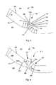
- Fig. 4 is a fragmentary sectional view of a panel according to another embodiment of the invention.
- a panel 200 comprises a core 206, a first surface 208 on a face side 202 of the panel 200, and a second surface 210 on a cavity side 204 of the panel 200.
- the panel 200 further comprises a convex design feature 212 comprising an apex 214, a first adjacent base 218, and a second adjacent base 222.
- the convex feature is created by a stepped corrective push.
- the stepped corrective push comprises a first contact point 226, a second contact point 228, and a third contact point 230, each respectively located on the cavity side 204 of the panel 200.
- the three contact points 226, 228, 230 comprise a "triple ripple.”
- the three contact points 226, 228, 230 consolidate fiber at the apex of the convex design feature 212 on the face side 202 of the panel 250 by maximizing the compression forces pushing fiber toward the apex 214.
- the apex 214 of the convex design feature 212 has a first caliper 216, as measured between the apex 214 and the contact point 226.
- the first adjacent base 218 has base calipers 220a, 220b.
- the second adjacent base 222 has base calipers 224a, 224b. Both pairs of the base calipers 220a, 220b and 224a, 224b are less, or thinner, than the first caliper 216 at the apex 214.
- a die set for manufacture of the panel 200 has a face side 202 and a cavity side 204.
- the contact point 226 can be seen, as well as the contact points 228 and 230.
- the apex 214 is provided by push 214', whereas the bases 218 and 222 are provided by pushes 218' and 222'.
- the dies of Fig. 4A are configured so that the surfaces 202 and 204 form the mat so as to have molded into it the features that are desired, such as the coves, beads, panels, etc.
- Panels utilizing the principles of the present invention may be formed with any number of design elements, each having a variety of shapes and sizes.
- the thickness of the design elements may be increased from the lowest or deepest portion of the contoured region progressively to the flat regions.
- the thicknesses of design elements may gradually increase, with adjacent design elements having a variation in thickness between 5-7%. This increase in thickness may also be measured from a zone where the greatest change in deflection occurs from a previous zone, as apart from a lowest portion.
- the formation of design features having sharp convex deflection points in the profile requires a certain degree of additional compression adjacent to a convex point on both flanking sides of that convex point.
- the thinner sections adjacent to the convex point cause lateral movement of the fiber during press closure, thereby causing consolidation of fiber into the apex or convex point on the face side of the profile element.
- the thinner sections should not exceed a 5-7% reduction compared to the total thickness of the referenced bisected point (i.e. apex).
- a panel formed with these dimensions can have a constant, or uniform, surface density, due to the movement of wood fiber material caused by internal forces during the forming process.
- the constant surface density may penetrate the depth of the panel a sufficient amount to avoid paint soaking in. For example, this properly densified surface depth may be in the range of .025"-.030".
- Fig. 5 is a fragmentary sectional view of a panel according to another embodiment of the invention.
- the panel 300 shown in Fig. 5 comprises a core 310, a first surface 306 on a face side 302 of the panel 300, and a second surface 308 on a cavity side 304 of the panel 300, the second surface 308 oppositely disposed the first surface 306.
- the panel 300 is divided into three regions, or zones: a first flat region 312, a second flat region 314, and a contoured region 316.
- the flat regions 312, 314, or the normal zones, comprise the thickest portion of the panel 300, whereas the panel 300 is thinner in the contoured region 316.
- the contoured region 316 extends below the flat regions and comprises a plurality of design features, including a bevel 318, a first convex feature 320, and a second convex feature 322. Each region comprises a constant or changing thickness or caliper.
- the first flat region 312 comprises a caliper 324.
- the caliper of the panel 300 progressively decreases as the distance from the flat region 312 increases.
- the bevel 318 is closer to the first flat region 312 than the first convex feature 320.
- the caliper 326 at the bevel 318 is thinner than the flat region caliper 324, but thicker than the caliper 328 at the first convex feature 320.
- the caliper 328 of the first convex feature 320 is larger than the caliper 330 of the second convex feature 322.
- the second convex feature 322 comprises a first base 336 proximate to the flat region 312 and a second base 338 distant from the flat region 312.
- the first base 336 comprises a first caliper 332 and the second base 338 comprises a second caliper 334.
- the caliper 334 at the second base 338 distant from the flat region 312 is deflected approximately 45°from the flat region 312, and has the highest angle of deflection from the flat region 312 of any section of the contoured region 316.
- the smallest caliper, or thinnest section, of the contoured region is at the highest angle of deflection from the flat region.
- the panel 300 may be formed to have the thinnest section at the caliper 334.
- the section 340 of the panel 300 is shown as the deepest section of the contoured region 316.
- the smallest caliper of the contoured region is at the deepest section of the contoured region.
- the caliper 342 at the deepest section 340 is the smallest caliper of the panel 300.
- a die set having surfaces 302 and 304 is provided for forming the panel 300.
- structures of the dies forming corresponding features in the panel 300 are shown by like numbers augmented with a '.
- flat region 312 is formed by 312'
- flat 314 is formed by 314'.
- the dies of Fig. 5A have formed therein structures that create or mold into the mat the desired structural and ornamental features required for the panel 300.
- a mat of material is formed to have a first surface, a core, and a second surface oppositely disposed the first surface.
- the density of the panel is formed to be uniform, or substantially constant, across the first surface, and decreases through the core of the panel.
- Different amounts of pressure may be applied to different regions, or zones of the mat in order to give the finished panel the desired properties. For instance, less pressure will be applied to a convex feature such as a bed than to the bead's adjacent bases or cove portions, allowing the internal forces of the mat to push material towards the surface of the panel and into the bead.
- Fig. 6 is a flow diagram of another method according to the invention.
- a mat of material is first provided at 602.
- the mat of material is a wood fiber composite material, although flakes, wafers, particles, strands, or mixtures thereof may be used.
- the mat is preferably formed from wood fibers, and more preferably formed into a high density fiberboard.
- a combination of steam and chemicals may be added to the mat before it is molded.
- a vapor injection method using vapor ammonia and a surface spray method using liquid dimethyl sulfoxide may be applied to either one of or both sides of the mat before it is pressed.
- These chemicals may be used to further manipulate the density profile and enhance the cleavage strength of the panel.
- the mat of material is formed through a molding process, such as compression molding.
- the mat of material may be introduced to a die set, and be subject to a combination of heat and pressure.
- One or more flat regions, or normal zones, are formed in the mat of material 604.
- the flat regions of the mat may be formed with a constant thickness, or caliper.
- the flat regions of the mat may ultimately form the border, or outside area, of a contoured door panel.
- a contoured region is formed in the mat of material.
- the contoured region is formed at the same time as the flat region.
- the contoured region may have an overall concave or depressed shape.
- Panels according to the present invention may comprise one or more contoured regions.
- the contoured region may be formed such that the smallest caliper of the contoured region is at the section of the contoured region most distant from the flat region, at the deepest section of the contoured region, and/or at the section with the highest angle of deflection from the contoured region.
- the mat of material may be formed such that the thickness of the contoured region progressively decreases as the distance from the flat region increases, thus creating a panel with the smallest caliper at the section of the contoured region most distant from the flat region.
- a convex feature is then formed in contoured region of the mat of material 608.
- the convex feature comprises a first adjacent base with a first caliper, a second adjacent base with a second caliper, and an apex with a third caliper greater than the first caliper and the second caliper.
- a surface pattern may be formed on one or both surfaces of the mat of material 610.
- This pattern can have a fine surface texture small enough to not fully fill with fiber during the pressing cycle.
- Such textured patterns allow gases and moisture to vent from the mat during the molding process.
- the texture depth to width ratio may be 2 to 1.
- the pattern may be random direction lines or a uniform grid crossing each other or parallel to each other.
- the frequency of the pattern may be no closer than a ratio of 3 units of flat for line of surface texture.
- the texture element width may be between 0.0005" to 0.002", having a depth between 0.001" to 0.004".
- a molded panel without brown line defects such as those provided by the present invention may be used in a number of applications.
- a panel will be used as a door facing having design features which simulate contoured paneling.
- the frame may comprise a lock stile, a hinge stile, a bottom rail, and a top rail.
- the door facings are preferably adhesively attached to the frame, though they may also be press fitted, mechanically fastened, or fastened through any other suitable means.
- the first and second door facings may be identical, or the exterior side door facing may differ from the interior side. Additionally, the interior of the door may be provided with a core material.
Landscapes
- Engineering & Computer Science (AREA)
- Architecture (AREA)
- Civil Engineering (AREA)
- Structural Engineering (AREA)
- Life Sciences & Earth Sciences (AREA)
- Wood Science & Technology (AREA)
- Manufacturing & Machinery (AREA)
- Forests & Forestry (AREA)
- Dry Formation Of Fiberboard And The Like (AREA)
- Laminated Bodies (AREA)
- Panels For Use In Building Construction (AREA)
- Bending Of Plates, Rods, And Pipes (AREA)
- Building Environments (AREA)
Applications Claiming Priority (1)
| Application Number | Priority Date | Filing Date | Title |
|---|---|---|---|
| US22714209P | 2009-07-21 | 2009-07-21 |
Publications (2)
| Publication Number | Publication Date |
|---|---|
| EP2280128A2 true EP2280128A2 (fr) | 2011-02-02 |
| EP2280128A3 EP2280128A3 (fr) | 2013-01-09 |
Family
ID=42711990
Family Applications (1)
| Application Number | Title | Priority Date | Filing Date |
|---|---|---|---|
| EP10170188A Withdrawn EP2280128A3 (fr) | 2009-07-21 | 2010-07-20 | Panneau et son procédé de fabrication |
Country Status (5)
| Country | Link |
|---|---|
| US (1) | US20110020609A1 (fr) |
| EP (1) | EP2280128A3 (fr) |
| CN (1) | CN102029637A (fr) |
| AU (1) | AU2010203100A1 (fr) |
| NZ (2) | NZ586925A (fr) |
Citations (3)
| Publication number | Priority date | Publication date | Assignee | Title |
|---|---|---|---|---|
| US6511567B1 (en) | 1999-03-31 | 2003-01-28 | International Paper Company | Composite building components and method of making same |
| US6743318B2 (en) | 2001-11-28 | 2004-06-01 | Masonite Corporation | Method of manufacturing consolidated cellulosic panels with contoured surfaces and variable basis weight |
| US7426806B2 (en) | 2000-04-20 | 2008-09-23 | Masonite Corporation | Reverse molded panel, method of manufacture, and door manufactured therefrom |
Family Cites Families (19)
| Publication number | Priority date | Publication date | Assignee | Title |
|---|---|---|---|---|
| US2682083A (en) * | 1952-11-05 | 1954-06-29 | Curtis Companies Inc | Method of making molded panels |
| US2964792A (en) * | 1954-10-22 | 1960-12-20 | Abitibi Power & Paper Co | Synthetic lumber pressure slam |
| US3171872A (en) * | 1961-11-24 | 1965-03-02 | Cardwell Machine Company | Method and apparatus for producing particle board and the like |
| US4552797A (en) * | 1983-03-28 | 1985-11-12 | Furnier-U.Sperrholzwerk | Plate-shaped covering profile and method for manufacturing the same |
| US5543234A (en) * | 1994-06-20 | 1996-08-06 | Masonite Corporation | Molded wood composites having non-blistering profile with uniform paintability and nesting |
| US5534352A (en) * | 1994-08-16 | 1996-07-09 | Masonite Corporation | Finishing process for textured panels, and structures made thereby |
| US6602610B2 (en) * | 1998-09-11 | 2003-08-05 | Masonite Corporation | Molded wood composites having improved horizontal contact nesting profile |
| US6773791B1 (en) * | 1999-03-31 | 2004-08-10 | Masonite Corporation | Composite building components, and method of making same |
| WO2001081055A1 (fr) * | 2000-04-20 | 2001-11-01 | Masonite Corporation | Panneau moule sur son envers |
| US7021015B2 (en) * | 2000-04-20 | 2006-04-04 | Masonite Corporation | Reverse molded plant-on panel component, method of manufacture, and method of decorating a door therewith |
| DE10204321B4 (de) * | 2002-02-01 | 2007-05-03 | Fritz Egger Gmbh & Co. | Formteil und Verfahren zu dessen Herstellung |
| US7644551B2 (en) * | 2002-08-20 | 2010-01-12 | Masonite International Corporation | Double skin door apparatus |
| US20040036197A1 (en) * | 2002-08-21 | 2004-02-26 | Janiga Eugene R. | Methods of forming molded, coated wood composites |
| US7022414B2 (en) * | 2003-04-30 | 2006-04-04 | Jeld-Wen, Inc. | Molded skin with curvature |
| US7314534B2 (en) * | 2003-07-23 | 2008-01-01 | Masonite Corporation | Method of making multi-ply door core, multi-ply door core, and door manufactured therewith |
| EP1755843A2 (fr) * | 2004-01-16 | 2007-02-28 | Masonite Corporation | Porte, parement de porte a moulage profond et leurs procedes de fabrication |
| DE102004056131B4 (de) * | 2004-11-16 | 2006-08-31 | Kronotec Ag | Schalldämmplatte |
| US8563118B2 (en) * | 2007-04-19 | 2013-10-22 | Masonite Corporation | Molded door facing blank and door including same |
| EP2193050B1 (fr) * | 2007-09-28 | 2013-04-10 | Lydall, Inc. | Panneau d'isolation acoustique de véhicule moulé et façonné et son procédé de fabrication |
-
2010
- 2010-07-20 EP EP10170188A patent/EP2280128A3/fr not_active Withdrawn
- 2010-07-21 AU AU2010203100A patent/AU2010203100A1/en not_active Abandoned
- 2010-07-21 US US12/840,596 patent/US20110020609A1/en not_active Abandoned
- 2010-07-21 CN CN201010530338XA patent/CN102029637A/zh active Pending
- 2010-07-21 NZ NZ586925A patent/NZ586925A/en not_active IP Right Cessation
- 2010-07-21 NZ NZ595832A patent/NZ595832A/xx not_active IP Right Cessation
Patent Citations (3)
| Publication number | Priority date | Publication date | Assignee | Title |
|---|---|---|---|---|
| US6511567B1 (en) | 1999-03-31 | 2003-01-28 | International Paper Company | Composite building components and method of making same |
| US7426806B2 (en) | 2000-04-20 | 2008-09-23 | Masonite Corporation | Reverse molded panel, method of manufacture, and door manufactured therefrom |
| US6743318B2 (en) | 2001-11-28 | 2004-06-01 | Masonite Corporation | Method of manufacturing consolidated cellulosic panels with contoured surfaces and variable basis weight |
Also Published As
| Publication number | Publication date |
|---|---|
| NZ595832A (en) | 2012-10-26 |
| AU2010203100A1 (en) | 2011-02-10 |
| US20110020609A1 (en) | 2011-01-27 |
| CN102029637A (zh) | 2011-04-27 |
| NZ586925A (en) | 2011-11-25 |
| EP2280128A3 (fr) | 2013-01-09 |
Similar Documents
| Publication | Publication Date | Title |
|---|---|---|
| US10988975B2 (en) | Molded door facing blank and method of forming same | |
| US12320186B2 (en) | Door skin stacking | |
| US11371279B2 (en) | Door skins, doors, and nested door skins | |
| JP6538311B2 (ja) | 連続圧縮成形用ツーリングダイの、ずらして配置された斜面 | |
| AU670276B2 (en) | Methods of designing embossing dies and making wood composite products | |
| KR20010072097A (ko) | 편평한 나무복합물로부터 성형문거죽을 제조하는 방법,그것으로부터 생산된 문거죽, 및 그것으로 제조된 문 | |
| US20180142515A1 (en) | Door, method of making door, and stack of doors | |
| EP1473127A2 (fr) | Parement de porte moule | |
| US20030129361A1 (en) | Sheet formed from a flat core and from curved parts bonded thereto, and process for producing this sheet | |
| US20190195004A1 (en) | Door and door skin | |
| EP2280128A2 (fr) | Panneau et son procédé de fabrication | |
| US20220034153A1 (en) | Door skins and method of making | |
| HK1156908A (en) | Panel and method of making the same | |
| US20120040042A1 (en) | Composite Mold with Expandable Boot | |
| KR101581394B1 (ko) | 엠보 형성이 가능한 금형 | |
| CZ28072U1 (cs) | Zařízení na výrobu desek na bázi dřeva s vylepšeným hustotním profilem | |
| HK1126264B (en) | Molded door facing blank, method of forming a molded door facing blank, and mold press for forming a molded door facing blank | |
| HK1113771B (en) | Method for producing formed wooden article | |
| HK1113771A1 (en) | Method for producing formed wooden article |
Legal Events
| Date | Code | Title | Description |
|---|---|---|---|
| PUAI | Public reference made under article 153(3) epc to a published international application that has entered the european phase |
Free format text: ORIGINAL CODE: 0009012 |
|
| AK | Designated contracting states |
Kind code of ref document: A2 Designated state(s): AL AT BE BG CH CY CZ DE DK EE ES FI FR GB GR HR HU IE IS IT LI LT LU LV MC MK MT NL NO PL PT RO SE SI SK SM TR |
|
| AX | Request for extension of the european patent |
Extension state: BA ME RS |
|
| RAP1 | Party data changed (applicant data changed or rights of an application transferred) |
Owner name: MASONITE CORPORATION |
|
| PUAL | Search report despatched |
Free format text: ORIGINAL CODE: 0009013 |
|
| AK | Designated contracting states |
Kind code of ref document: A3 Designated state(s): AL AT BE BG CH CY CZ DE DK EE ES FI FR GB GR HR HU IE IS IT LI LT LU LV MC MK MT NL NO PL PT RO SE SI SK SM TR |
|
| AX | Request for extension of the european patent |
Extension state: BA ME RS |
|
| RIC1 | Information provided on ipc code assigned before grant |
Ipc: E04C 2/32 20060101ALI20121204BHEP Ipc: E04C 2/16 20060101ALI20121204BHEP Ipc: B27N 5/00 20060101ALI20121204BHEP Ipc: E06B 3/70 20060101AFI20121204BHEP |
|
| 17P | Request for examination filed |
Effective date: 20130709 |
|
| RBV | Designated contracting states (corrected) |
Designated state(s): AL AT BE BG CH CY CZ DE DK EE ES FI FR GB GR HR HU IE IS IT LI LT LU LV MC MK MT NL NO PL PT RO SE SI SK SM TR |
|
| 17Q | First examination report despatched |
Effective date: 20151014 |
|
| RAP1 | Party data changed (applicant data changed or rights of an application transferred) |
Owner name: MASONITE CORPORATION |
|
| STAA | Information on the status of an ep patent application or granted ep patent |
Free format text: STATUS: THE APPLICATION IS DEEMED TO BE WITHDRAWN |
|
| 18D | Application deemed to be withdrawn |
Effective date: 20180201 |