EP2280160A2 - Soupape d'injection de carburant dotée d'une capacité à petites quantités augmentée - Google Patents
Soupape d'injection de carburant dotée d'une capacité à petites quantités augmentée Download PDFInfo
- Publication number
- EP2280160A2 EP2280160A2 EP10164578A EP10164578A EP2280160A2 EP 2280160 A2 EP2280160 A2 EP 2280160A2 EP 10164578 A EP10164578 A EP 10164578A EP 10164578 A EP10164578 A EP 10164578A EP 2280160 A2 EP2280160 A2 EP 2280160A2
- Authority
- EP
- European Patent Office
- Prior art keywords
- valve
- seat
- needle
- throttle
- fuel injection
- Prior art date
- Legal status (The legal status is an assumption and is not a legal conclusion. Google has not performed a legal analysis and makes no representation as to the accuracy of the status listed.)
- Withdrawn
Links
- 238000002347 injection Methods 0.000 title claims abstract description 55
- 239000007924 injection Substances 0.000 title claims abstract description 55
- 239000000446 fuel Substances 0.000 title claims description 33
- 238000002485 combustion reaction Methods 0.000 claims description 5
- 238000010417 needlework Methods 0.000 abstract 1
- 239000012530 fluid Substances 0.000 description 7
- 230000000694 effects Effects 0.000 description 5
- 238000010586 diagram Methods 0.000 description 4
- 230000000284 resting effect Effects 0.000 description 2
- 239000002283 diesel fuel Substances 0.000 description 1
- 238000009434 installation Methods 0.000 description 1
- 238000004519 manufacturing process Methods 0.000 description 1
- 239000007787 solid Substances 0.000 description 1
Images



Classifications
-
- F—MECHANICAL ENGINEERING; LIGHTING; HEATING; WEAPONS; BLASTING
- F02—COMBUSTION ENGINES; HOT-GAS OR COMBUSTION-PRODUCT ENGINE PLANTS
- F02M—SUPPLYING COMBUSTION ENGINES IN GENERAL WITH COMBUSTIBLE MIXTURES OR CONSTITUENTS THEREOF
- F02M45/00—Fuel-injection apparatus characterised by having a cyclic delivery of specific time/pressure or time/quantity relationship
- F02M45/02—Fuel-injection apparatus characterised by having a cyclic delivery of specific time/pressure or time/quantity relationship with each cyclic delivery being separated into two or more parts
- F02M45/04—Fuel-injection apparatus characterised by having a cyclic delivery of specific time/pressure or time/quantity relationship with each cyclic delivery being separated into two or more parts with a small initial part, e.g. initial part for partial load and initial and main part for full load
- F02M45/08—Injectors peculiar thereto
-
- F—MECHANICAL ENGINEERING; LIGHTING; HEATING; WEAPONS; BLASTING
- F02—COMBUSTION ENGINES; HOT-GAS OR COMBUSTION-PRODUCT ENGINE PLANTS
- F02M—SUPPLYING COMBUSTION ENGINES IN GENERAL WITH COMBUSTIBLE MIXTURES OR CONSTITUENTS THEREOF
- F02M61/00—Fuel-injectors not provided for in groups F02M39/00 - F02M57/00 or F02M67/00
- F02M61/16—Details not provided for in, or of interest apart from, the apparatus of groups F02M61/02 - F02M61/14
- F02M61/18—Injection nozzles, e.g. having valve seats; Details of valve member seated ends, not otherwise provided for
- F02M61/1866—Valve seats or member ends having multiple cones
-
- F—MECHANICAL ENGINEERING; LIGHTING; HEATING; WEAPONS; BLASTING
- F02—COMBUSTION ENGINES; HOT-GAS OR COMBUSTION-PRODUCT ENGINE PLANTS
- F02M—SUPPLYING COMBUSTION ENGINES IN GENERAL WITH COMBUSTIBLE MIXTURES OR CONSTITUENTS THEREOF
- F02M61/00—Fuel-injectors not provided for in groups F02M39/00 - F02M57/00 or F02M67/00
- F02M61/16—Details not provided for in, or of interest apart from, the apparatus of groups F02M61/02 - F02M61/14
- F02M61/18—Injection nozzles, e.g. having valve seats; Details of valve member seated ends, not otherwise provided for
- F02M61/1873—Valve seats or member ends having circumferential grooves or ridges, e.g. toroidal
-
- F—MECHANICAL ENGINEERING; LIGHTING; HEATING; WEAPONS; BLASTING
- F02—COMBUSTION ENGINES; HOT-GAS OR COMBUSTION-PRODUCT ENGINE PLANTS
- F02M—SUPPLYING COMBUSTION ENGINES IN GENERAL WITH COMBUSTIBLE MIXTURES OR CONSTITUENTS THEREOF
- F02M61/00—Fuel-injectors not provided for in groups F02M39/00 - F02M57/00 or F02M67/00
- F02M61/16—Details not provided for in, or of interest apart from, the apparatus of groups F02M61/02 - F02M61/14
- F02M61/18—Injection nozzles, e.g. having valve seats; Details of valve member seated ends, not otherwise provided for
- F02M61/1886—Details of valve seats not covered by groups F02M61/1866 - F02M61/188
-
- F—MECHANICAL ENGINEERING; LIGHTING; HEATING; WEAPONS; BLASTING
- F02—COMBUSTION ENGINES; HOT-GAS OR COMBUSTION-PRODUCT ENGINE PLANTS
- F02M—SUPPLYING COMBUSTION ENGINES IN GENERAL WITH COMBUSTIBLE MIXTURES OR CONSTITUENTS THEREOF
- F02M61/00—Fuel-injectors not provided for in groups F02M39/00 - F02M57/00 or F02M67/00
- F02M61/16—Details not provided for in, or of interest apart from, the apparatus of groups F02M61/02 - F02M61/14
- F02M61/20—Closing valves mechanically, e.g. arrangements of springs or weights or permanent magnets; Damping of valve lift
- F02M61/205—Means specially adapted for varying the spring tension or assisting the spring force to close the injection-valve, e.g. with damping of valve lift
-
- F—MECHANICAL ENGINEERING; LIGHTING; HEATING; WEAPONS; BLASTING
- F02—COMBUSTION ENGINES; HOT-GAS OR COMBUSTION-PRODUCT ENGINE PLANTS
- F02M—SUPPLYING COMBUSTION ENGINES IN GENERAL WITH COMBUSTIBLE MIXTURES OR CONSTITUENTS THEREOF
- F02M2200/00—Details of fuel-injection apparatus, not otherwise provided for
- F02M2200/28—Details of throttles in fuel-injection apparatus
Definitions
- the invention relates to a fuel injection valve for internal combustion engines with a valve body in which a bore is worked out, which is delimited at one end by a valve seat from which at least one injection channel goes off, and with a valve needle, which is arranged longitudinally displaceably in the bore and at its valve seat facing the end has a valve seat surface with which it cooperates to open and close the at least one injection channel with the valve seat and formed between the valve needle and the wall of the bore pressure chamber which can be filled with fuel under pressure, wherein between the valve body and the valve needle is arranged a throttle.
- Such a fuel injection valve is out of WO 2004/057180 A1 known.
- This fuel injection valve has a valve body in which a valve needle is arranged to be longitudinally displaceable.
- the valve needle has a guide portion which is mounted in the valve body.
- the guide section is followed by a pressure shoulder defining a bore filled with fuel.
- the bore is penetrated by a needle body of the valve needle, wherein the needle body end has a valve seat surface.
- a pressure surface is incorporated, which is connected at installation of the valve needle to the valve seat via a throttle with the pressure chamber.
- the invention is based on the object to provide a fuel injection valve, which works robustly at high injection rates (main injection), but can also reliably ensure especially small injection rates (pilot injection).
- the arrangement of the throttle between the seat and the seat valve seat is achieved that at small strokes and high fluid velocities a pressure drop below the effective throttle area is set. Due to its geometric position, this leads to a reduction in the needle force. As a result, the injection rate is reduced compared to an embodiment without the throttle and, as a result, the pilot injection rate or the pilot injection quantity is reduced. Lower pilot injection quantities offer combustion advantages.
- the throttle is integrated into the seat heel.
- the presence of the seat heel is essential for the adjustment of the throttle effect desired according to the invention.
- the seat heel is designed as a stepped seat heel and the throttle designed as a transversely to the direction of movement of the valve needle aligned constriction between the valve needle and the valve body.
- the throttle can be adjusted very precisely.
- a precisely defined zero stroke is adjustable when resting on the valve seat valve needle, which determines the free cross-sectional area of the throttle. It is essential that the throttle is always fully open (with respect to the throttle function) when the valve needle is resting on the valve seat. It is therefore not an additional seat to avoid the associated wear and drift problem.
- a small opening stroke of the valve needle and high fluid velocities a lower dynamic pressure (pressure drop) occurs behind the throttle, which leads to a lowering of the characteristic needle force.
- the seat heel is designed as a Schrägsitzabsatz and the throttle is incorporated as at least approximately parallel to the valve seat aligned constriction in the seat heel. It is possible to realize the Schrägsitzabsatz by appropriate design of the valve body or the valve needle. As a result, the production cost can be reduced.
- the throttle is integrated directly into the valve seat.
- the valve needle adjacent to a seating area of the valve seat surface at least on the hole-side end of the valve body side facing a reduced needle angle.
- the throttle effect according to the invention is achieved by this configuration.
- the seat angle and the apex angle of the valve needle and the valve body is reduced.
- the free area between the valve needle and the valve seat surface is only slightly changed during a small needle stroke, so that together with the reduced needle angle results in the desired pressure drop and thus the advantage of a low injection rate in a pilot injection.
- the seat angle and the apex angle of the valve needle and the valve body is less than 59 °, preferably between 29 ° and 49 °.
- the wall thickness of the valve body is simultaneously increased, which is in terms of the strength at high Railley in the range of for example 3000 bar advantage.
- the seating area is a conical section surface or alternatively an annular surface.
- a tapered portion surface is advantageous in terms of durability, while in an annular surface, the throttle effect is more precisely adjustable.
- FIG. 1 shows the injection-side end portion of a fuel injection valve.
- the fuel injection valve has a valve body 1 in which a bore 2 is incorporated. On the injection-side end of the valve body 1, this has a valve seat 3, which opens into a blind hole 4. From the blind hole 4 go from injection ducts 5, is injected via the fuel, in particular diesel fuel in the respective associated combustion chamber of the internal combustion engine.
- a valve needle 6 is arranged longitudinally displaceable.
- the valve needle 6 is mounted in a non-illustrated region of the fuel injection valve with a guide portion in the valve body 1.
- a pressure shoulder also not shown, of which the valve needle 6 is arranged to form a pressure chamber 7 spaced from the bore 2 in the valve body 1.
- the pressure chamber 7 is supplied via a suitable supply fuel under pressure.
- the valve needle 6 has a valve seat surface 8, which prevents the supply of fuel from the pressure chamber 7 in the blind hole 4.
- the fuel injection valve has a seat 9 between the pressure chamber 7 and the valve seat 3 or the valve seat surface 8.
- the seat heel is designed as a stepped seat paragraph 9a.
- a throttle 10 is incorporated, which is formed by recessed into the seat heel 9 constrictions 11a, 11b.
- the throttle 10 is dimensioned such that it still leaves a flow cross section when the fuel injection valve is closed. With small strokes of the valve needle 6 and high fluid velocities, a pressure drop below the throttle area-that is to say in the region toward the valve seat 3 -is set.
- A is a reactor with A D ; A stroke with A H and P throttle with p D designated.
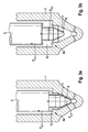
- FIG. 3a is a small opening stroke of the valve needle 6 and in FIG. 3b a large opening stroke of the valve needle 6 is shown.
- the needle force F N is shown via the needle stroke N H at high pressures.
- the solid curve shows the needle force, which results without throttle 10, while the dashed curve represents the conditions that result when using the throttle 10 according to the invention. At low pressures, the effect of the throttle 10 weakens, which is desirable in the idle range.
- the injection rate ER over the injection time E Z is shown. It can be seen that in the region of the pre-injection shown on the left by the throttle 10, a reduced pre-injection quantity (represented by the dashed curve) is achieved.
- the main injection quantity (shown on the right side of the diagram) remains unchanged. For example, with 10 ⁇ m zero stroke, the injection quantity is about 1.0mm 3 per stroke, with 60 ⁇ m zero stroke it is about 1.2mm 3 per stroke. The small quantity capability can thus be improved by about 20% in this example.
- the main injection quantity remains constant.
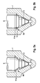
- FIGS. 5a and 5b show a seat paragraph 9, which is formed as a Schrägsitzabsatz 9b. It is in FIG. 5a the constriction 11 b incorporated in the valve body 1 in the upper region of the valve seat 3, while in the FIG. 5b the valve seat 3 is formed in the region of the throttle 10 in a straight line and the constriction 11a is arranged in the region of the valve needle-side oblique seating shoulder 9b.
- any combination not shown, are possible within the scope of the invention.
- FIG. 6a shows in a blind hole a valve needle 6, which has a valve seat surface 8, which is designed as an annular surface 12. Only in the region of the annular surface 12, a sealed connection to the valve seat 3 is made in the closed state of the valve needle 6.
- the valve needle 6 each have a reduced needle angle.
- the seat angle of the valve needle 6 in the area of annular surface 12 and the needle angle and the apex angle of the valve body 1 are compared to the FIGS. 1 to 3 and 5 illustrated embodiments smaller, preferably configured in the range between 29 ° and 49 °. It is important here that the seat diameter remains the same as in the previous embodiments. The opening pressure thus remains the same. The seat length is thereby increased, whereby the throttling increases.
- FIG. 6b a corresponding embodiment is shown in a seat hole nozzle.
- the position of the annular surface 12 is displaced in the direction of the seat 9.
- the entire throttle range of the seat is extended.
- the seat thus additionally assumes the function of the throttle 10.
Landscapes
- Engineering & Computer Science (AREA)
- Chemical & Material Sciences (AREA)
- Combustion & Propulsion (AREA)
- Mechanical Engineering (AREA)
- General Engineering & Computer Science (AREA)
- Fuel-Injection Apparatus (AREA)
Applications Claiming Priority (1)
| Application Number | Priority Date | Filing Date | Title |
|---|---|---|---|
| DE200910028089 DE102009028089A1 (de) | 2009-07-29 | 2009-07-29 | Kraftstoffeinspritzventil mit erhöhter Kleinmengenfähigkeit |
Publications (2)
| Publication Number | Publication Date |
|---|---|
| EP2280160A2 true EP2280160A2 (fr) | 2011-02-02 |
| EP2280160A3 EP2280160A3 (fr) | 2013-01-16 |
Family
ID=43033014
Family Applications (1)
| Application Number | Title | Priority Date | Filing Date |
|---|---|---|---|
| EP10164578A Withdrawn EP2280160A3 (fr) | 2009-07-29 | 2010-06-01 | Soupape d'injection de carburant dotée d'une capacité à petites quantités augmentée |
Country Status (2)
| Country | Link |
|---|---|
| EP (1) | EP2280160A3 (fr) |
| DE (1) | DE102009028089A1 (fr) |
Cited By (2)
| Publication number | Priority date | Publication date | Assignee | Title |
|---|---|---|---|---|
| DE102013209251A1 (de) | 2013-05-17 | 2014-11-20 | Robert Bosch Gmbh | Kraftstoffeinspritzventil für Brennkraftmaschinen |
| WO2015043913A1 (fr) * | 2013-09-27 | 2015-04-02 | Robert Bosch Gmbh | Injecteur de carburant et procédé pour le fabriquer |
Family Cites Families (8)
| Publication number | Priority date | Publication date | Assignee | Title |
|---|---|---|---|---|
| DE3303470A1 (de) * | 1983-02-02 | 1984-08-02 | Jaroslavskij savod diselnoj apparatury, Jaroslavl | Einspritzduese fuer verbrennungsmotore |
| JPS6026163A (ja) * | 1983-07-23 | 1985-02-09 | Toyota Motor Corp | デイ−ゼルエンジンの燃料噴射弁 |
| DE3734587A1 (de) * | 1987-10-13 | 1989-05-03 | Bosch Gmbh Robert | Kraftstoff-einspritzduese fuer brennkraftmaschinen |
| DE19755057A1 (de) * | 1997-12-11 | 1999-06-17 | Bosch Gmbh Robert | Kraftstoffeinspritzdüse für selbstzündende Brennkraftmaschinen |
| DE10039083A1 (de) * | 2000-08-10 | 2002-02-21 | Bosch Gmbh Robert | Brennstoffeinspritzventil |
| DE10259169A1 (de) | 2002-12-18 | 2004-07-01 | Robert Bosch Gmbh | Kraftstoffeinspritzventil für Brennkraftmaschine |
| US7527041B2 (en) * | 2005-07-08 | 2009-05-05 | Westport Power Inc. | Fuel injection valve |
| JP2009138614A (ja) * | 2007-12-05 | 2009-06-25 | Mitsubishi Heavy Ind Ltd | 蓄圧式燃料噴射装置の燃料噴射弁 |
-
2009
- 2009-07-29 DE DE200910028089 patent/DE102009028089A1/de not_active Withdrawn
-
2010
- 2010-06-01 EP EP10164578A patent/EP2280160A3/fr not_active Withdrawn
Non-Patent Citations (1)
| Title |
|---|
| None |
Cited By (2)
| Publication number | Priority date | Publication date | Assignee | Title |
|---|---|---|---|---|
| DE102013209251A1 (de) | 2013-05-17 | 2014-11-20 | Robert Bosch Gmbh | Kraftstoffeinspritzventil für Brennkraftmaschinen |
| WO2015043913A1 (fr) * | 2013-09-27 | 2015-04-02 | Robert Bosch Gmbh | Injecteur de carburant et procédé pour le fabriquer |
Also Published As
| Publication number | Publication date |
|---|---|
| EP2280160A3 (fr) | 2013-01-16 |
| DE102009028089A1 (de) | 2011-02-10 |
Similar Documents
| Publication | Publication Date | Title |
|---|---|---|
| DE10210976A1 (de) | Kraftstoffeinspritzventil für Brennkraftmaschinen | |
| EP2470771B1 (fr) | Injecteur de carburant | |
| EP1509693B1 (fr) | Soupape d'injection de carburant pour moteurs a combustion interne | |
| WO2004092576A1 (fr) | Injecteur de carburant pour moteur a combustion interne | |
| EP1117921B1 (fr) | Injecteur de carburant pour un système carburant à rampe commune | |
| EP1346143A1 (fr) | Soupape d'injection de carburant destinee a des moteurs a combustion interne | |
| EP2280160A2 (fr) | Soupape d'injection de carburant dotée d'une capacité à petites quantités augmentée | |
| EP1518049A1 (fr) | Soupape d'injection de carburant pour moteurs a combustion interne | |
| DE10322826A1 (de) | Kraftstoffeinspritzventil für Brennkraftmaschinen | |
| EP2496822B1 (fr) | Buse d'injection pour un injecteur de carburant sans fuite | |
| EP3060789B1 (fr) | Injecteur de carburant | |
| DE10318989A1 (de) | Kraftstoffeinspritzventil für Brennkraftmaschinen | |
| DE10219608A1 (de) | Kraftstoffeinspritzventil für Brennkraftmaschinen | |
| EP1576283A1 (fr) | Soupape d'injection de carburant pour moteurs a combustion interne | |
| DE102004022428A1 (de) | Einspritzventil für Brennkraftmaschinen | |
| EP1719904A1 (fr) | Injecteur de carburant | |
| DE102011086249A1 (de) | Kraftstoffinjektor | |
| EP2655850B1 (fr) | Injecteur de carburant pour moteurs à combustion interne | |
| DE102005005713A1 (de) | Düsenbaugruppe und Einspritzventil | |
| AT414159B (de) | Einspritzdüse | |
| WO2011076465A1 (fr) | Injecteur de carburant sans fuite | |
| DE102012213535A1 (de) | Kraftstoffinjektor | |
| WO2015086560A1 (fr) | Zone de raccordement entre une conduite haute pression et une chambre haute pression et élément d'injection de carburant muni d'une zone de raccordement | |
| EP2726731B1 (fr) | Injecteur de carburant | |
| DE102005027853A1 (de) | Kraftstoffeinspritzventil für Brennkraftmaschinen |
Legal Events
| Date | Code | Title | Description |
|---|---|---|---|
| PUAI | Public reference made under article 153(3) epc to a published international application that has entered the european phase |
Free format text: ORIGINAL CODE: 0009012 |
|
| AK | Designated contracting states |
Kind code of ref document: A2 Designated state(s): AL AT BE BG CH CY CZ DE DK EE ES FI FR GB GR HR HU IE IS IT LI LT LU LV MC MK MT NL NO PL PT RO SE SI SK SM TR |
|
| AX | Request for extension of the european patent |
Extension state: BA ME RS |
|
| PUAL | Search report despatched |
Free format text: ORIGINAL CODE: 0009013 |
|
| AK | Designated contracting states |
Kind code of ref document: A3 Designated state(s): AL AT BE BG CH CY CZ DE DK EE ES FI FR GB GR HR HU IE IS IT LI LT LU LV MC MK MT NL NO PL PT RO SE SI SK SM TR |
|
| AX | Request for extension of the european patent |
Extension state: BA ME RS |
|
| RIC1 | Information provided on ipc code assigned before grant |
Ipc: F02M 61/18 20060101ALI20121213BHEP Ipc: F02M 61/20 20060101ALI20121213BHEP Ipc: F02M 45/08 20060101AFI20121213BHEP |
|
| STAA | Information on the status of an ep patent application or granted ep patent |
Free format text: STATUS: THE APPLICATION IS DEEMED TO BE WITHDRAWN |
|
| 18D | Application deemed to be withdrawn |
Effective date: 20130717 |