EP2280166A1 - Procédé et système pour faire fonctionner un aérogénérateur - Google Patents
Procédé et système pour faire fonctionner un aérogénérateur Download PDFInfo
- Publication number
- EP2280166A1 EP2280166A1 EP09725503A EP09725503A EP2280166A1 EP 2280166 A1 EP2280166 A1 EP 2280166A1 EP 09725503 A EP09725503 A EP 09725503A EP 09725503 A EP09725503 A EP 09725503A EP 2280166 A1 EP2280166 A1 EP 2280166A1
- Authority
- EP
- European Patent Office
- Prior art keywords
- generator
- mode
- power
- grid
- wind turbine
- Prior art date
- Legal status (The legal status is an assumption and is not a legal conclusion. Google has not performed a legal analysis and makes no representation as to the accuracy of the status listed.)
- Withdrawn
Links
Images


Classifications
-
- F—MECHANICAL ENGINEERING; LIGHTING; HEATING; WEAPONS; BLASTING
- F03—MACHINES OR ENGINES FOR LIQUIDS; WIND, SPRING, OR WEIGHT MOTORS; PRODUCING MECHANICAL POWER OR A REACTIVE PROPULSIVE THRUST, NOT OTHERWISE PROVIDED FOR
- F03D—WIND MOTORS
- F03D9/00—Adaptations of wind motors for special use; Combinations of wind motors with apparatus driven thereby; Wind motors specially adapted for installation in particular locations
- F03D9/20—Wind motors characterised by the driven apparatus
- F03D9/25—Wind motors characterised by the driven apparatus the apparatus being an electrical generator
-
- F—MECHANICAL ENGINEERING; LIGHTING; HEATING; WEAPONS; BLASTING
- F03—MACHINES OR ENGINES FOR LIQUIDS; WIND, SPRING, OR WEIGHT MOTORS; PRODUCING MECHANICAL POWER OR A REACTIVE PROPULSIVE THRUST, NOT OTHERWISE PROVIDED FOR
- F03D—WIND MOTORS
- F03D9/00—Adaptations of wind motors for special use; Combinations of wind motors with apparatus driven thereby; Wind motors specially adapted for installation in particular locations
- F03D9/20—Wind motors characterised by the driven apparatus
- F03D9/25—Wind motors characterised by the driven apparatus the apparatus being an electrical generator
- F03D9/255—Wind motors characterised by the driven apparatus the apparatus being an electrical generator connected to electrical distribution networks; Arrangements therefor
- F03D9/257—Wind motors characterised by the driven apparatus the apparatus being an electrical generator connected to electrical distribution networks; Arrangements therefor the wind motor being part of a wind farm
-
- H—ELECTRICITY
- H02—GENERATION; CONVERSION OR DISTRIBUTION OF ELECTRIC POWER
- H02J—ELECTRIC POWER NETWORKS; CIRCUIT ARRANGEMENTS OR SYSTEMS FOR SUPPLYING OR DISTRIBUTING ELECTRIC POWER; SYSTEMS FOR STORING ELECTRIC ENERGY
- H02J3/00—Circuit arrangements for AC mains or AC distribution networks
- H02J3/38—Arrangements for feeding a single network from two or more generators or sources in parallel; Arrangements for feeding already energised networks from additional generators or sources in parallel
- H02J3/381—Dispersed generators
-
- H—ELECTRICITY
- H02—GENERATION; CONVERSION OR DISTRIBUTION OF ELECTRIC POWER
- H02P—CONTROL OR REGULATION OF ELECTRIC MOTORS, ELECTRIC GENERATORS OR DYNAMO-ELECTRIC CONVERTERS; CONTROLLING TRANSFORMERS, REACTORS OR CHOKE COILS
- H02P3/00—Arrangements for stopping or slowing electric motors, generators, or dynamo-electric converters
- H02P3/06—Arrangements for stopping or slowing electric motors, generators, or dynamo-electric converters for stopping or slowing an individual dynamo-electric motor or dynamo-electric converter
- H02P3/18—Arrangements for stopping or slowing electric motors, generators, or dynamo-electric converters for stopping or slowing an individual dynamo-electric motor or dynamo-electric converter for stopping or slowing an AC motor
- H02P3/22—Arrangements for stopping or slowing electric motors, generators, or dynamo-electric converters for stopping or slowing an individual dynamo-electric motor or dynamo-electric converter for stopping or slowing an AC motor by short-circuit or resistive braking
-
- H—ELECTRICITY
- H02—GENERATION; CONVERSION OR DISTRIBUTION OF ELECTRIC POWER
- H02P—CONTROL OR REGULATION OF ELECTRIC MOTORS, ELECTRIC GENERATORS OR DYNAMO-ELECTRIC CONVERTERS; CONTROLLING TRANSFORMERS, REACTORS OR CHOKE COILS
- H02P9/00—Arrangements for controlling electric generators for the purpose of obtaining a desired output
- H02P9/007—Control circuits for doubly fed generators
-
- H—ELECTRICITY
- H02—GENERATION; CONVERSION OR DISTRIBUTION OF ELECTRIC POWER
- H02P—CONTROL OR REGULATION OF ELECTRIC MOTORS, ELECTRIC GENERATORS OR DYNAMO-ELECTRIC CONVERTERS; CONTROLLING TRANSFORMERS, REACTORS OR CHOKE COILS
- H02P9/00—Arrangements for controlling electric generators for the purpose of obtaining a desired output
- H02P9/42—Arrangements for controlling electric generators for the purpose of obtaining a desired output to obtain desired frequency without varying speed of the generator
-
- H—ELECTRICITY
- H02—GENERATION; CONVERSION OR DISTRIBUTION OF ELECTRIC POWER
- H02J—ELECTRIC POWER NETWORKS; CIRCUIT ARRANGEMENTS OR SYSTEMS FOR SUPPLYING OR DISTRIBUTING ELECTRIC POWER; SYSTEMS FOR STORING ELECTRIC ENERGY
- H02J2101/00—Supply or distribution of decentralised, dispersed or local electric power generation
- H02J2101/20—Dispersed power generation using renewable energy sources
- H02J2101/28—Wind energy
-
- H—ELECTRICITY
- H02—GENERATION; CONVERSION OR DISTRIBUTION OF ELECTRIC POWER
- H02J—ELECTRIC POWER NETWORKS; CIRCUIT ARRANGEMENTS OR SYSTEMS FOR SUPPLYING OR DISTRIBUTING ELECTRIC POWER; SYSTEMS FOR STORING ELECTRIC ENERGY
- H02J3/00—Circuit arrangements for AC mains or AC distribution networks
- H02J3/38—Arrangements for feeding a single network from two or more generators or sources in parallel; Arrangements for feeding already energised networks from additional generators or sources in parallel
- H02J3/46—Controlling the sharing of generated power between the generators, sources or networks
- H02J3/50—Controlling the sharing of reactive power
-
- H—ELECTRICITY
- H02—GENERATION; CONVERSION OR DISTRIBUTION OF ELECTRIC POWER
- H02P—CONTROL OR REGULATION OF ELECTRIC MOTORS, ELECTRIC GENERATORS OR DYNAMO-ELECTRIC CONVERTERS; CONTROLLING TRANSFORMERS, REACTORS OR CHOKE COILS
- H02P2101/00—Special adaptation of control arrangements for generators
- H02P2101/15—Special adaptation of control arrangements for generators for wind-driven turbines
-
- H—ELECTRICITY
- H02—GENERATION; CONVERSION OR DISTRIBUTION OF ELECTRIC POWER
- H02P—CONTROL OR REGULATION OF ELECTRIC MOTORS, ELECTRIC GENERATORS OR DYNAMO-ELECTRIC CONVERTERS; CONTROLLING TRANSFORMERS, REACTORS OR CHOKE COILS
- H02P2207/00—Indexing scheme relating to controlling arrangements characterised by the type of motor
- H02P2207/07—Doubly fed machines receiving two supplies both on the stator only wherein the power supply is fed to different sets of stator windings or to rotor and stator windings
- H02P2207/073—Doubly fed machines receiving two supplies both on the stator only wherein the power supply is fed to different sets of stator windings or to rotor and stator windings wherein only one converter is used, the other windings being supplied without converter, e.g. doubly-fed induction machines
-
- Y—GENERAL TAGGING OF NEW TECHNOLOGICAL DEVELOPMENTS; GENERAL TAGGING OF CROSS-SECTIONAL TECHNOLOGIES SPANNING OVER SEVERAL SECTIONS OF THE IPC; TECHNICAL SUBJECTS COVERED BY FORMER USPC CROSS-REFERENCE ART COLLECTIONS [XRACs] AND DIGESTS
- Y02—TECHNOLOGIES OR APPLICATIONS FOR MITIGATION OR ADAPTATION AGAINST CLIMATE CHANGE
- Y02E—REDUCTION OF GREENHOUSE GAS [GHG] EMISSIONS, RELATED TO ENERGY GENERATION, TRANSMISSION OR DISTRIBUTION
- Y02E10/00—Energy generation through renewable energy sources
- Y02E10/70—Wind energy
- Y02E10/72—Wind turbines with rotation axis in wind direction
-
- Y—GENERAL TAGGING OF NEW TECHNOLOGICAL DEVELOPMENTS; GENERAL TAGGING OF CROSS-SECTIONAL TECHNOLOGIES SPANNING OVER SEVERAL SECTIONS OF THE IPC; TECHNICAL SUBJECTS COVERED BY FORMER USPC CROSS-REFERENCE ART COLLECTIONS [XRACs] AND DIGESTS
- Y02—TECHNOLOGIES OR APPLICATIONS FOR MITIGATION OR ADAPTATION AGAINST CLIMATE CHANGE
- Y02E—REDUCTION OF GREENHOUSE GAS [GHG] EMISSIONS, RELATED TO ENERGY GENERATION, TRANSMISSION OR DISTRIBUTION
- Y02E10/00—Energy generation through renewable energy sources
- Y02E10/70—Wind energy
- Y02E10/76—Power conversion electric or electronic aspects
Definitions
- the present invention relates to wind turbines provided with asynchronous doubly fed generators and with at least one power converter, being novel in that, under certain circumstances, it enables the turbine to operate as a Full Converter (FC) system, a Doubly Fed (DFIG) system or as an Asynchronous (AS) system, thereby increasing turbine availability.
- FC Full Converter
- DFIG Doubly Fed
- AS Asynchronous
- variable speed wind turbines appeared with generators isolated from the grid by a power converter connected to the stator of the generator, thereby allowing to deliver the power generated by the turbine to the grid.
- This type of system is known as a Full Converter (FC) system, as they require a power converter to manage the power of the stator windings.
- FC Full Converter
- the present invention applies to wind turbines provided with asynchronous doubly fed generators and with at least one power converter, being novel in that under certain circumstances it enables the turbine to operate as a FC system, DFIG system or Asynchronous (AS) system, thereby increasing turbine availability.
- the present invention solves the problem discussed above by providing tolerance in case of anomalies in the power converter and other system components, thus allowing to select among the FC, DFIG or AS operation modes.
- the state of the art includes inventions meant to prevent loss of availability in wind turbines due to operation failures in system components, or to protect them in case of critical operation conditions in which the integrity of the components is endangered (for example, the power converter).
- Patent application US20060214428A1 describes a method for connecting power converters in parallel such that in case of failure of one power converter the remaining ones can continue to operate, thereby preventing the stoppage of the wind turbine, operating always in DFIG mode.
- Patent application EP1768223A2 describes a topology for power converters placed in parallel and attacking different windings of the generator, the object of which is to increase the efficiency of conversion and tolerate failure of one of the power converters, operating always in FC mode, so that if one converter fails power continues to be generated, although nominal power will never be reached.
- Patent application US20060227578A1 describes a plurality of converters placed in parallel with their output composed of a transformer with several windings connected in series. This proposal, as the prior ones, increases tolerance to failures of the converter by using a plurality of converters.
- Patent application US20070024059A1 describes the possibility of activating the semiconductors of the power converter in a short-circuit mode, thereby preventing energy from passing through the converter, avoiding for example an excessive power flow that may damage it. However, it does not allow operating the turbine if the converter is not operative. This situation may occur, for example, in case of failure of the semiconductors of the power electronics or failure of the converter control electronics.
- Patent US7012409B2 describes a system whereby an auxiliary power converter makes it possible, in case of grid contingencies, to control the reactive power supplied and used of the grid.
- Patent application WO2008/026973A1 describes an operation method in which the asynchronous generator is connected to the grid either directly or through a power converter, in order to optimize generation at different rotation speeds.
- the present invention avoids placing redundant power converters and ensures alternative operation modes to continue generating up to 100% of nominal power.
- the invention consists of a new power generation system designed such that it allows changing among the FC, DFIG and AS operation modes, allowing, in a preferred embodiment, to operate at up to 100% of nominal power in one of the various operation modes in which it can function without having any redundant elements.
- Nominal power is understood as the maximum characteristic power of each operation mode (FC - DFIG - AS).
- Partial loss of operability is understood as any failure of at least one system component that prevents generation of 100% of the nominal power in an operation mode.
- the solution proposed by this invention allows generating up to 100% of nominal power in at least one of the other two operation modes.
- the entry and exit conditions for each of the operation modes are:
- the invention allows selecting the operation mode that maximizes the power generation of the wind turbine.
- the method of the invention requires using the following components: at least one wound-rotor asynchronous generator with at least one electrically independent stator, at least one power converter able to control rotor and/or stator currents of said generator in amplitude, frequency and phase, and a set of manoeuvring elements allowing to connect and disconnect the aforementioned components.
- This method is characterized in that it comprises operation in an operation mode selected among FC, DFIG and AS.
- the term "power converter” refers to any topology using power electronics and the associated control. These elements constitute a functional unit in charge of controlling rotor and/or stator magnitudes, such as currents, such that it is possible to deliver power to the electric grid, operating at variable or fixed speed.
- the power converter can be a topology formed by one or several back-to-back converters (reversible AC-DC-AC conversions through a continuous bus, where AC stands for alternating current and DC for direct current) or any other topology that carries out said functionality.
- Each of the power converters can be governed by a controller associated to it. If there are several power converters (with their corresponding controllers) there must be at least one controller able to coordinate the operation of the various converters.
- the object of this invention is to allow selecting and changing among the three operation modes FC, DFIG and AS to maximize the power generated by the wind turbine, which can be up to 100% of the nominal power in the selected operation mode even in conditions of partial loss of operability.
- the method considers disconnecting the rotor of said generator and isolating it from the power converter, short-circuiting the rotor and operating the wind turbine with the generator rotor short-circuited and isolated from the power converter, to allow operating the wind turbine generator in AS mode.
- the procedure of the invention comprises the following stages:
- the operation method for changing from mode FC to DFIG and, once operating in DFIG returning to FC comprises the following stages:
- the operation method for changing from FC mode to AS mode, and when operating in AS mode changing to FC or DFIG mode comprises the following stages:
- the operation method for changing from DFIG mode to AS mode, and when operating in AS mode changing to FC or DFIG mode, comprises the following stages:
- the systems includes, in addition to the elements needed to control the wind turbine:
- a preferred embodiment of the invention includes conventional means for reducing current surges associated to coupling an asynchronous generator (short-circuited rotor) such as soft starters.
- the above-described method can be executed using manoeuvring elements both dependent and independent of the converter.
- Elements dependent of the converter are the power electronics and the manoeuvring elements associated to it.
- Elements independent of the converter are the power electronics and manoeuvring elements not associated to it.
- the method also enables controlling the rotor resistance by short-circuiting the rotor of the generator either directly to ground or using other elements such as resistors, inductors, condensers, thyristors, IGBT's, diodes or any combination thereof.
- the converter or components of the converter not in charge of controlling the generator, provided they are operative, can be used to generate reactive power.
- the method of the invention comprises operating the system according to an operation mode selected among FC, DFIG and AS.
- the change of operation mode is performed when the system is disconnected from the grid and without generating power, using the various manoeuvring elements and by changing the control of the electrical system.
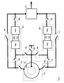
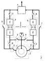
- the system comprises two power controllers (101) and (102) and one generator (110).
- the power converters (101) and (102) include the controllers needed for their operation.
- the wind turbine is represented acting as an FC system, so that the manoeuvre element (105) must be closed to short-circuit the rotor (113) of the generator; the rotor is electrically isolated by the open manoeuvring elements (104) and (106), and the stator of the generator is connected to the power converters by the closed manoeuvring elements (115) and (116). All the power of the generator is evacuated through the manoeuvring elements (109) and (107) connected to the power converters. The power converters are connected to the grid through the manoeuvring elements (103) and (108) (closed). Connection to the grid can be established directly or through a transformer (114).
- the operation mode configuration is changed from FC to DFIG.
- the process starts by isolating the power converter (101) or part thereof (101a and/or 101b) in which a failure has occurred, opening the manoeuvring elements (109 and/or 103 and 104).
- the generator stator is isolated from the grid (manoeuvring elements 115 and 116 open).
- the power converter (102) is connected to the rotor (113) of the generator (110), manoeuvring element (107) open, manoeuvring element (106) closed and manoeuvring element (105) open to undo the short-circuit of the generator rotor, and the generator stator is connected to the grid with the manoeuvring elements (115) and (116) closed.
- the manoeuvring elements 100, 111, 115 and 116) are closed. If the power converter (101) is disabled for operation in FC mode and one of its components (101a or 101b) is operative, this component can be used to generate reactive power.
- the manoeuvring element (109) is closed in case of failure of part (101b) (with 101a operative) or the manoeuvring element (103) is closed in cause of failure of part (101a) (with 101b operative).
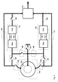
- a configuration change is performed from operation mode DFIG to AS ( figure 5 ).
- the process begins by isolating the two faulty power converters (101a and/or 101b) and (102a and/or 102b), with manoeuvring elements (104 and 106) open and the manoeuvring element needed to isolate the faulty part of the converter (109, 103, 107 and 108).
- the generator stator is isolated from the grid (manoeuvring elements 115 and 116 open).
- the generator stator is connected to the grid with the manoeuvring elements 115 and 116 closed, the rotor (113) of the generator (110) is short-circuited with the manoeuvring element (105) closed.
- the manoeuvre elements 100 and 111 are closed.
- the system can continue operating at up to 100% nominal power of the AS operation mode. If one of the components of the power converters (101a, 101b, 102a, 102b) are operative, they can be used to generate reactive power.
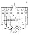
- a process similar to that of the previous case is followed, opening the manoeuvring elements of the faulty components and closing the manoeuvring elements of the operative components.
- the generator (110) is disconnected from the grid with the manoeuvring elements 115, 116, 104 and 106.
- the manoeuvring elements 100, 111, 109, 107, 103 and 108 are closed.
- the power converters (101a, 101b, 102a, 102b) can be used to generate reactive power.
- the invention is applicable to a doubly fed wind turbine, as it can be operated in DFIG or AS mode.
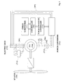
- a power converter (702) to allow coupling the wind turbine to the electric grid (703) at variable speed.
- the generator (704) is of the wound rotor induction type with its windings accessible to the power converter (702) by brush rings, allowing the power converter (702) to power the generator rotor (hence its name, doubly-fed induction generator, DFIG).
- the manoeuvring elements are a switch (707) that allows disconnecting the power converter (702) from the electric grid (703) and a switch (705) for connecting and disconnecting the stator from the electric grid (703).
- the manoeuvring elements (705 and 707) can be contactors, switches, thermo-magnetic relays, or the like.
- the controller of the wind turbine (709) is in charge of supervising and acting on all subsystems that make up the wind turbine, such as the hydraulic unit, pitch systems, yaw systems, atmospheric condition and electric grid monitoring systems, power converter controller (710), or the like.
- the power converter (702) In the wind turbine DFIG operation mode the power converter (702) is in charge of injecting in the rotor of the generator (704) current enabling to generate power at a variable speed.
- a set of manoeuvring elements (708 and 713) are introduced between the generator rotor and the power converter (702).
- these elements are external to the power converter (702) and operated by the wind turbine controller (709) together with the other subsystems mentioned above.
- the manoeuvring elements (708 and 713) are controlled by the power converter controller (710) or by a combination of both controllers (709 and 710).
- Figure 6 shows the specific case of the system operating in the DFIG operation mode, where:
Landscapes
- Engineering & Computer Science (AREA)
- Power Engineering (AREA)
- Life Sciences & Earth Sciences (AREA)
- Sustainable Development (AREA)
- Sustainable Energy (AREA)
- Chemical & Material Sciences (AREA)
- Combustion & Propulsion (AREA)
- Mechanical Engineering (AREA)
- General Engineering & Computer Science (AREA)
- Control Of Eletrric Generators (AREA)
Applications Claiming Priority (3)
| Application Number | Priority Date | Filing Date | Title |
|---|---|---|---|
| ES200800870A ES2327487B1 (es) | 2008-03-28 | 2008-03-28 | Sistema y metodo de operacion asincrona aplicable a un aerogenerador del tipo doblemente alimentado (dfig). |
| ES200803132A ES2351901B1 (es) | 2008-11-03 | 2008-11-03 | Método y sistema para operar un aerogenerador. |
| PCT/ES2009/000120 WO2009118433A1 (fr) | 2008-03-28 | 2009-03-06 | Procédé et système pour faire fonctionner un aérogénérateur |
Publications (1)
| Publication Number | Publication Date |
|---|---|
| EP2280166A1 true EP2280166A1 (fr) | 2011-02-02 |
Family
ID=41113002
Family Applications (1)
| Application Number | Title | Priority Date | Filing Date |
|---|---|---|---|
| EP09725503A Withdrawn EP2280166A1 (fr) | 2008-03-28 | 2009-03-06 | Procédé et système pour faire fonctionner un aérogénérateur |
Country Status (5)
| Country | Link |
|---|---|
| US (1) | US20110057446A1 (fr) |
| EP (1) | EP2280166A1 (fr) |
| CN (1) | CN102066748B (fr) |
| CA (1) | CA2719434A1 (fr) |
| WO (1) | WO2009118433A1 (fr) |
Cited By (6)
| Publication number | Priority date | Publication date | Assignee | Title |
|---|---|---|---|---|
| WO2011112571A3 (fr) * | 2010-03-11 | 2012-03-08 | Siemens Aktiengesellschaft | Procédé et système permettant d'atténuer des oscillations résonantes hyposynchrones dans un système électrique à l'aide d'une turbine éolienne |
| WO2012097816A1 (fr) | 2011-01-17 | 2012-07-26 | Vestas Wind Systems A/S | Exploitation de turbines éoliennes dans des conditions de défaillance de convertisseur |
| EP2492502A1 (fr) * | 2011-02-25 | 2012-08-29 | Siemens Aktiengesellschaft | Éolienne dotée d'un générateur |
| EP3182546A1 (fr) * | 2015-12-18 | 2017-06-21 | Gamesa Innovation & Technology, S.L. | Système de génération d'énergie d'une turbine éolienne à multiples convertisseurs et son procédé de commande |
| WO2019110090A1 (fr) * | 2017-12-05 | 2019-06-13 | Siemens Aktiengesellschaft | Dispositif comportant une machine asynchrone et procédé permettant son fonctionnement |
| WO2021197607A1 (fr) * | 2020-04-02 | 2021-10-07 | Abb Power Grids Switzerland Ag | Agencement de support électrique pour un réseau électrique |
Families Citing this family (17)
| Publication number | Priority date | Publication date | Assignee | Title |
|---|---|---|---|---|
| WO2004047284A1 (fr) * | 2002-11-15 | 2004-06-03 | Zephyr Corporation | Aerogenerateur |
| FI119086B (fi) * | 2006-11-06 | 2008-07-15 | Abb Oy | Menetelmä ja järjestely tuulivoimalan yhteydessä |
| JP5260555B2 (ja) * | 2009-06-05 | 2013-08-14 | 三菱重工業株式会社 | 系統安定化装置、方法、及び風力発電システム |
| AU2010257226A1 (en) * | 2010-11-30 | 2012-06-14 | Mitsubishi Heavy Industries, Ltd. | Wind turbine generator |
| DE102011000459B4 (de) * | 2011-02-02 | 2017-11-02 | Universität Kassel | Verfahren zur Lieferung von Blindstrom mit einem Umrichter sowie Umrichteranordnung und Energieversorgungsanlage |
| DK2492504T3 (en) * | 2011-02-25 | 2018-04-16 | Siemens Ag | Windmill |
| US8558405B2 (en) * | 2011-05-26 | 2013-10-15 | Siemens Aktiengesellschaft | Method and system for operating and controlling a wind turbine to prevent excitation of subsynchronous oscillations within the wind turbine |
| US8373307B2 (en) * | 2011-05-26 | 2013-02-12 | General Electric Company | Methods and systems for direct current power transmission |
| JP5942393B2 (ja) * | 2011-11-18 | 2016-06-29 | 株式会社日立製作所 | 回転電機システムまたは風力発電システム。 |
| DK177684B1 (en) * | 2012-12-21 | 2014-03-03 | Envision Energy Denmark Aps | Wind turbine having a HTS generator with a plurality of phases |
| CN103138669B (zh) * | 2013-02-06 | 2016-07-06 | 远景能源(江苏)有限公司 | 一种风力发电机组及其工作模式切换方法 |
| JP6158109B2 (ja) * | 2014-02-07 | 2017-07-05 | 株式会社東芝 | 過電圧保護装置 |
| ES2809478T3 (es) | 2015-03-17 | 2021-03-04 | Abb Schweiz Ag | Sistema de excitación con un dispositivo de protección frente a una falla de arco |
| CN106160606B (zh) * | 2015-03-24 | 2019-09-17 | 台达电子工业股份有限公司 | 风力发电系统及其控制方法 |
| ES2613902B1 (es) * | 2015-11-26 | 2018-03-14 | Gamesa Innovation & Technology, S.L. | Método y sistemas de monitorización en tiempo real del estado del aislamiento de los devanados de generadores eólicos |
| EP3923462A4 (fr) * | 2019-02-09 | 2022-11-23 | Nam Soo Myung | Machine électromagnétique utilisant la liaison de champ magnétique de multiples fils d'enroulement multiphase |
| CN111756284B (zh) * | 2020-06-17 | 2024-07-16 | 江西洪都航空工业集团有限责任公司 | 一种双余度设计的双通道飞机发电机控制装置 |
Family Cites Families (15)
| Publication number | Priority date | Publication date | Assignee | Title |
|---|---|---|---|---|
| US1A (en) | 1836-07-13 | John Ruggles | Locomotive steam-engine for rail and other roads | |
| US5028804A (en) * | 1989-06-30 | 1991-07-02 | The State Of Oregon Acting By And Through The State Board Of Higher Education On Behalf Of Oregon State University | Brushless doubly-fed generator control system |
| US5798631A (en) * | 1995-10-02 | 1998-08-25 | The State Of Oregon Acting By And Through The State Board Of Higher Education On Behalf Of Oregon State University | Performance optimization controller and control method for doubly-fed machines |
| US6600240B2 (en) * | 1997-08-08 | 2003-07-29 | General Electric Company | Variable speed wind turbine generator |
| US6628101B2 (en) * | 2001-04-20 | 2003-09-30 | General Electric Company | Electronic shorting of wound rotor windings |
| US20040021437A1 (en) * | 2002-07-31 | 2004-02-05 | Maslov Boris A. | Adaptive electric motors and generators providing improved performance and efficiency |
| EP1540811B1 (fr) * | 2002-09-10 | 2010-12-01 | DeWind Co. | Procede d'utilisation d'une installation eolienne comportant une cascade hypersynchrone |
| EP1625457A4 (fr) * | 2003-05-02 | 2015-04-22 | Xantrex Technology Inc | Systeme de commande de generateur d'induction a double alimentation |
| DE10327344A1 (de) | 2003-06-16 | 2005-01-27 | Repower Systems Ag | Windenergieanlage |
| DE102004003657B4 (de) * | 2004-01-24 | 2012-08-23 | Semikron Elektronik Gmbh & Co. Kg | Stromrichterschaltungsanordnung und zugehöriges Ansteuerverfahren für Generatoren mit dynamisch veränderlicher Leistungsabgabe |
| US7359223B2 (en) * | 2005-03-30 | 2008-04-15 | General Electric Company | Power converter system and method |
| US7239036B2 (en) | 2005-07-29 | 2007-07-03 | General Electric Company | System and method for power control in wind turbines |
| WO2007035411A2 (fr) * | 2005-09-16 | 2007-03-29 | Satcon Technology Corporation | Machine d'induction a rotor bobine |
| US7439714B2 (en) * | 2005-09-27 | 2008-10-21 | Gamesa Innovation & Technology, S.L. | Method for operation of a converter system |
| CN101507076B (zh) * | 2006-08-30 | 2011-08-31 | Abb研究有限公司 | 功率转换器装置和方法 |
-
2009
- 2009-03-06 WO PCT/ES2009/000120 patent/WO2009118433A1/fr not_active Ceased
- 2009-03-06 CA CA2719434A patent/CA2719434A1/fr not_active Abandoned
- 2009-03-06 EP EP09725503A patent/EP2280166A1/fr not_active Withdrawn
- 2009-03-06 US US12/934,073 patent/US20110057446A1/en not_active Abandoned
- 2009-03-06 CN CN2009801111494A patent/CN102066748B/zh not_active Expired - Fee Related
Non-Patent Citations (1)
| Title |
|---|
| See references of WO2009118433A1 * |
Cited By (11)
| Publication number | Priority date | Publication date | Assignee | Title |
|---|---|---|---|---|
| WO2011112571A3 (fr) * | 2010-03-11 | 2012-03-08 | Siemens Aktiengesellschaft | Procédé et système permettant d'atténuer des oscillations résonantes hyposynchrones dans un système électrique à l'aide d'une turbine éolienne |
| WO2012097816A1 (fr) | 2011-01-17 | 2012-07-26 | Vestas Wind Systems A/S | Exploitation de turbines éoliennes dans des conditions de défaillance de convertisseur |
| EP2492502A1 (fr) * | 2011-02-25 | 2012-08-29 | Siemens Aktiengesellschaft | Éolienne dotée d'un générateur |
| US8766467B2 (en) | 2011-02-25 | 2014-07-01 | Siemens Aktiengesellschaft | Wind turbine with a generator |
| EP3182546A1 (fr) * | 2015-12-18 | 2017-06-21 | Gamesa Innovation & Technology, S.L. | Système de génération d'énergie d'une turbine éolienne à multiples convertisseurs et son procédé de commande |
| US11081890B2 (en) | 2015-12-18 | 2021-08-03 | Siemens Gamesa Renewable Energy Innovation & Technology, S.L. | Power generation system of a multi-converter wind turbine and control method thereof |
| WO2019110090A1 (fr) * | 2017-12-05 | 2019-06-13 | Siemens Aktiengesellschaft | Dispositif comportant une machine asynchrone et procédé permettant son fonctionnement |
| US11482956B2 (en) | 2017-12-05 | 2022-10-25 | Siemens Energy Global GmbH & Co. KG | Arrangement comprising an asynchronous machine and method for operating same |
| WO2021197607A1 (fr) * | 2020-04-02 | 2021-10-07 | Abb Power Grids Switzerland Ag | Agencement de support électrique pour un réseau électrique |
| JP2023510033A (ja) * | 2020-04-02 | 2023-03-10 | ヒタチ・エナジー・スウィツァーランド・アクチェンゲゼルシャフト | 電力グリッド用の電力サポート装置 |
| US11996696B2 (en) | 2020-04-02 | 2024-05-28 | Hitachi Energy, Ltd | Power supporting arrangement for a power grid |
Also Published As
| Publication number | Publication date |
|---|---|
| US20110057446A1 (en) | 2011-03-10 |
| CN102066748A (zh) | 2011-05-18 |
| CN102066748B (zh) | 2013-07-24 |
| WO2009118433A1 (fr) | 2009-10-01 |
| CA2719434A1 (fr) | 2009-10-01 |
Similar Documents
| Publication | Publication Date | Title |
|---|---|---|
| EP2280166A1 (fr) | Procédé et système pour faire fonctionner un aérogénérateur | |
| US8013461B2 (en) | Power conversion system and method for a rotary power generation system | |
| EP1664527B1 (fr) | Systeme redondant de commande de pas d'aube con u pour une eolienne, et procede de commande d'une eolienne | |
| EP2197095A2 (fr) | Transformateurs électriques | |
| US20070279815A1 (en) | Redundant electrical brake and protection system for electric generators | |
| JP2014122628A (ja) | 高温超電導多相発電機を有する風力タービン | |
| EP2637278A1 (fr) | Unité de commande intelligente de l'alimentation pour un maintien d'alimentation en creux de tension, ainsi que son utilisation | |
| EP2400653A1 (fr) | Appareil de génération d'énergie éolienne | |
| US9797375B2 (en) | Blade pitch system with a dual winding actuator | |
| WO2020239425A1 (fr) | Commande de transformateur d'éolienne | |
| US12081161B2 (en) | Control system and method for the rotor side converter of a doubly-fed induction generator in a wind turbine | |
| US20140103886A1 (en) | Method for producing reactive current with a converter and converter arrangement and energy supply plant | |
| EP2017953A2 (fr) | Système de commande à vitesse variable | |
| US11434873B2 (en) | Method for operating electrical machines | |
| EP4084318A1 (fr) | Installation d'énergie éolienne et procédé | |
| EP4120547A1 (fr) | Installation d'énergie éolienne et procédé | |
| EP3840212B1 (fr) | Réponse sélective de limitation en tension d'un convertisseur de puissance pour atténuer les défaillances de dispositif | |
| US12140122B2 (en) | Wind turbine electrical power generating system | |
| EP4315587B1 (fr) | Installation d'énergie éolienne et procédé | |
| ES2327487B1 (es) | Sistema y metodo de operacion asincrona aplicable a un aerogenerador del tipo doblemente alimentado (dfig). | |
| EP4084319A1 (fr) | Installation d'énergie éolienne et procédé | |
| WO2024037696A1 (fr) | Protection haute tension d'électrolyseur dans un parc éolien | |
| ES2351901A1 (es) | Método y sistema para operar un aerogenerador. |
Legal Events
| Date | Code | Title | Description |
|---|---|---|---|
| PUAI | Public reference made under article 153(3) epc to a published international application that has entered the european phase |
Free format text: ORIGINAL CODE: 0009012 |
|
| 17P | Request for examination filed |
Effective date: 20101026 |
|
| AK | Designated contracting states |
Kind code of ref document: A1 Designated state(s): AT BE BG CH CY CZ DE DK EE ES FI FR GB GR HR HU IE IS IT LI LT LU LV MC MK MT NL NO PL PT RO SE SI SK TR |
|
| AX | Request for extension of the european patent |
Extension state: AL BA RS |
|
| RIN1 | Information on inventor provided before grant (corrected) |
Inventor name: AURTENETXEA LARRINAGA, SERGIO Inventor name: OLEA OREGI, ENEKO Inventor name: CALVO MADARIAGA, XABIER Inventor name: ELORRIAGA LLANOS, JOSU Inventor name: GARMENDIA OLARREAGA, IKER Inventor name: SIMON SEGURA, SUSANA Inventor name: PEREZ BARBACHANO, JAVIER Inventor name: SOLE LOPEZ, DAVID Inventor name: CARCAR MAYOR, AINHOA Inventor name: ACEDO SANCHEZ, JORGE Inventor name: MAYOR LUSARRETA, JESUS |
|
| DAX | Request for extension of the european patent (deleted) | ||
| RAP1 | Party data changed (applicant data changed or rights of an application transferred) |
Owner name: INGETEAM POWER TECHNOLOGY, S.A. |
|
| STAA | Information on the status of an ep patent application or granted ep patent |
Free format text: STATUS: THE APPLICATION IS DEEMED TO BE WITHDRAWN |
|
| 18D | Application deemed to be withdrawn |
Effective date: 20141001 |