EP2280182A1 - Kupplungselement mit einem Bewegungsübertragungsmechanismus mit Spulenfeder und Reibungseingriff - Google Patents
Kupplungselement mit einem Bewegungsübertragungsmechanismus mit Spulenfeder und Reibungseingriff Download PDFInfo
- Publication number
- EP2280182A1 EP2280182A1 EP10171318A EP10171318A EP2280182A1 EP 2280182 A1 EP2280182 A1 EP 2280182A1 EP 10171318 A EP10171318 A EP 10171318A EP 10171318 A EP10171318 A EP 10171318A EP 2280182 A1 EP2280182 A1 EP 2280182A1
- Authority
- EP
- European Patent Office
- Prior art keywords
- sleeve
- clutch member
- drum
- spring
- force
- Prior art date
- Legal status (The legal status is an assumption and is not a legal conclusion. Google has not performed a legal analysis and makes no representation as to the accuracy of the status listed.)
- Withdrawn
Links
Images

Classifications
-
- F—MECHANICAL ENGINEERING; LIGHTING; HEATING; WEAPONS; BLASTING
- F16—ENGINEERING ELEMENTS AND UNITS; GENERAL MEASURES FOR PRODUCING AND MAINTAINING EFFECTIVE FUNCTIONING OF MACHINES OR INSTALLATIONS; THERMAL INSULATION IN GENERAL
- F16D—COUPLINGS FOR TRANSMITTING ROTATION; CLUTCHES; BRAKES
- F16D13/00—Friction clutches
- F16D13/08—Friction clutches with a helical band or equivalent member, which may be built up from linked parts, with more than one turn embracing a drum or the like, with or without an additional clutch actuating the end of the band
-
- F—MECHANICAL ENGINEERING; LIGHTING; HEATING; WEAPONS; BLASTING
- F16—ENGINEERING ELEMENTS AND UNITS; GENERAL MEASURES FOR PRODUCING AND MAINTAINING EFFECTIVE FUNCTIONING OF MACHINES OR INSTALLATIONS; THERMAL INSULATION IN GENERAL
- F16D—COUPLINGS FOR TRANSMITTING ROTATION; CLUTCHES; BRAKES
- F16D23/00—Details of mechanically-actuated clutches not specific for one distinct type
- F16D23/12—Mechanical clutch-actuating mechanisms arranged outside the clutch as such
-
- F—MECHANICAL ENGINEERING; LIGHTING; HEATING; WEAPONS; BLASTING
- F16—ENGINEERING ELEMENTS AND UNITS; GENERAL MEASURES FOR PRODUCING AND MAINTAINING EFFECTIVE FUNCTIONING OF MACHINES OR INSTALLATIONS; THERMAL INSULATION IN GENERAL
- F16D—COUPLINGS FOR TRANSMITTING ROTATION; CLUTCHES; BRAKES
- F16D47/00—Systems of clutches, or clutches and couplings, comprising devices of types grouped under at least two of the following sets of groups: F16D1/00 - F16D9/00, F16D11/00 - F16D23/00, F16D25/00 - F16D29/00, F16D31/00 - F16D39/00, F16D41/00 - F16D45/00
- F16D47/02—Systems of clutches, or clutches and couplings, comprising devices of types grouped under at least two of the following sets of groups: F16D1/00 - F16D9/00, F16D11/00 - F16D23/00, F16D25/00 - F16D29/00, F16D31/00 - F16D39/00, F16D41/00 - F16D45/00 of which at least one is a coupling
Definitions
- the invention relates to the sector of clutch members for selective transmission of a rotational motion from a driving shaft always in movement to a driven shaft, particularly suitable for use on moving machine tools and vehicles in general.
- the invention relates to a clutch member in which the motion transmission mechanism is produced through a substantially cylindrical helical extension spring, arranged straddling the two shafts, wherein friction engagement means, which can be selectively activated or deactivated by external control means, determine driving of the two ends of said spring which, winding around said shafts, cause rotation in unison.
- a device of this type for use in photocopying machines is known from the patent US 4,440,280 .
- the member described comprises a first drum associated with a driving shaft and a second drum associated with a driven shaft.
- the driving shaft and the driven shaft are coaxial, in a manner such that the two drums are also coaxial.
- a coil spring is arranged around the two drums having the same external diameter.
- One end of the spring is fastened to the first drum and the other end is fastened to a first sleeve arranged therearound.
- a second sleeve is rotatingly mounted on the first sleeve and comprises a rubber ring facing a flange of the second drum.
- the spring does not touch the two drums, the first and the second sleeve and the coil spring rotate with the first drum but the second drum is motionless.
- the second sleeve is pressed against the flange of the second drum by a control disc that acts thereon, the rubber ring comes into contact with the flange, interrupting integral rotation between the first and the second sleeve.
- the spring therefore winds tightly around the first and the second drum to transfer the rotation movement of the first drum also to the second drum.
- a device of this kind presents limits and drawbacks that make it unsuitable for use on vehicles and machine tools that require to transfer high powers, forces and driving torques between two shafts and which work in movement, travelling over grounds that may even be very rough.
- the invention aims to overcome these limits, by producing a clutch member particularly suitable for use on moving means and vehicles in general, which makes use of machines safe for operators, does not cause undesirable actuation of the driven shaft, does not produce frictions, is reliable, of simple construction and does not require particular maintenance operations.
- a clutch member with motion transmission mechanism with coil spring and friction engagement comprising:
- the clutch member comprises an elastic element arranged for generating a force having the same direction as the axis of said driving and driven shafts, with a direction which opposes the movement of said first and second sleeve towards said flange.
- said elastic element comprises a counteracting spring arranged between said second drum and said first sleeve.
- said second sleeve is rotatingly associated with the first sleeve through the interposition of means to reduce sliding friction and said first sleeve is rotatingly associated with said first drum through further means to reduce sliding friction.
- the first sleeve that comes into contact with the flange of the first drum and a pad made of material with a high coefficient of friction can be interposed between the respective contact surfaces.
- the angle formed between the contact surfaces and the axis of the shafts differs from 90°.
- external actuator means of known type, which can be activated selectively by the operator, acting on the control lever to generate a force greater than the sum of the force of the counteracting spring and the minimum force suitable to produce engagement of the clutch member itself, in such a manner as to move the first sleeve against said flange and cause engagement of the clutch member itself.
- traction means acting on the same control lever selectively activatable by the operator, arranged for overcoming the force exerted by said spring and for moving said control lever away from said second sleeve, causing disengagement of the motion transmission member.
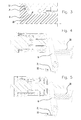
- a clutch member with motion transmission mechanism with coil spring and friction engagement of the normally open type, comprising a first drum 1 associated with a drive shaft 2 and a second drum 3 associated with a driven shaft 4, wherein said first and said second drum have the same external diameter and said driving and driven shafts are coaxial, i.e. are arranged along a same axis X.
- the transmission mechanism comprises a coil spring 5 arranged around the two drums 1 and 3, a first sleeve 6 arranged around said spring 5, slidingly associated with said driven shaft 4, a second sleeve 7 rotatingly associated with the first sleeve 6, a flange 8 associated with said first drum 1, a control lever 9 acting on said second sleeve 7 to move said first and second sleeve towards said flange 8, in opposition with a resisting elastic force generated by a counteracting spring 18.
- the coil spring 5 is produced with wire with substantially square section and comprises a first end 10 fastened to said first sleeve 6 and a second end 11 fastened to said second drum 3.
- the first sleeve 6 is rotatingly associated with the first drum 1 as a result of a ball bearing 12 interposed therebetween. Said ball bearing 12 can be omitted in the case in which there is no contact between the first sleeve 6 and the first drum 1.
- the second sleeve 7 is rotating associated with the first sleeve 6 as a result of a ball bearing 13 interposed therebetween.
- the flange 8 comprises a shoulder plane 14, to which there can be applied a pad 15 made of material with a high coefficient of friction, such as rubber, arranged for cooperating by sliding with a corresponding contact plane 16, which faces it, belonging to the first sleeve 6.
- the planes 14 and 16 form with the axis X an angle ⁇ that can be of around 90°, as shown in Figs. 1 and 2 , or of different amplitude, as shown in Fig. 3 .
- the control lever 9 is rotatingly associated with a fixed pin 17 in such a manner as to transmit, at the discretion of the operator acting thereon with actuator means, not shown, a force on the second sleeve 7 substantially directed along the axis X and with direction such as to cause movement of the sleeves 6 and 7 towards the flange 8.
- a counteracting spring 18 arranged for generating said resisting elastic force which opposes movement of said first and second sleeve towards said flange 8.
- a bearing 19 arranged for allowing mutual rotation without sliding friction between the two members.
- a clutch member with motion transmission mechanism with coil spring and friction engagement of the normally closed type, comprising all the components already illustrated above and with the same functions, besides a spring 20 acting constantly on the control lever 9, with a force greater than the one given by the sum of the force exerted by the counteracting spring 18 and the minimum force necessary to engage the clutch member itself, in such a manner as to hold the flange 8 and the first sleeve 6 constantly in mutual contact, ensuring constant engagement of the transmission member.
- the clutch member illustrated also comprises a cable 21 connected between the lever 9 and actuator means 22, for example of the pedal type, arranged for transmitting on the lever 9 a tractive force which, opposing the force generated by the spring 20, causes separation between the flange 8 and the first sleeve 6, and consequent disengagement of the transmission member.
- the external force to be applied to disengage the transmission member can be very small and substantially independent from the force transmitted between the two shafts.
- This closing makes the driving shaft 2 and the driven shaft 4 integral and obliges them to rotate with the same angular velocity, in a transient time that depends on the load acting on the driven shaft 4 and on the geometrical characteristics and the materials of the spring 5, of the drums 1 and 3, of the pad 15, of the thrust surface 16, etc..
- the characteristic of the clutch member lies in the fact that the tangential force required to close the spring 5 around the two drums 1 and 3, i.e. the force to be exerted at the end 10 of the same spring to cause engagement of the mechanical member, is much lower than the force that is created on the central coil of the spring, i.e. the coil that actually acts as connection between drum of the driving shaft and drum of the driven shaft and that in fact transmits the maximum force.
- the value of the engagement force is identical for the two ends 10 and 11. Its very low value also allows said ends of the spring 5 to be easily connected to the respective components of the transmission member.
- the clutch member according to the first variant of the invention requires a normally open clutch, which must be engaged only through the voluntary action of the operator on a control lever.
- the force required for actuation can be so low that it does not require any effort by the operator who, for example, simply by holding the guiding handlebars of the machine tool, already exerts this force without even feeling it.
- the member acts as any clutch of a mechanical transmission between rotating shafts, in which the driven shaft always rotates in unison with the driving shaft.
Landscapes
- Engineering & Computer Science (AREA)
- General Engineering & Computer Science (AREA)
- Mechanical Engineering (AREA)
- Physics & Mathematics (AREA)
- Electromagnetism (AREA)
- Vibration Dampers (AREA)
- Springs (AREA)
- Mechanical Operated Clutches (AREA)
Applications Claiming Priority (1)
| Application Number | Priority Date | Filing Date | Title |
|---|---|---|---|
| IT000031A ITCR20090031A1 (it) | 2009-07-30 | 2009-07-30 | Organo di innesto con meccanismo di trasmissione del moto a molla elicoidale e innesco ad attrito |
Publications (1)
| Publication Number | Publication Date |
|---|---|
| EP2280182A1 true EP2280182A1 (de) | 2011-02-02 |
Family
ID=41718402
Family Applications (1)
| Application Number | Title | Priority Date | Filing Date |
|---|---|---|---|
| EP10171318A Withdrawn EP2280182A1 (de) | 2009-07-30 | 2010-07-29 | Kupplungselement mit einem Bewegungsübertragungsmechanismus mit Spulenfeder und Reibungseingriff |
Country Status (2)
| Country | Link |
|---|---|
| EP (1) | EP2280182A1 (de) |
| IT (1) | ITCR20090031A1 (de) |
Cited By (7)
| Publication number | Priority date | Publication date | Assignee | Title |
|---|---|---|---|---|
| DE102012011998A1 (de) | 2012-06-16 | 2013-12-19 | Volkswagen Aktiengesellschaft | Schaltbare Kupplung und schaltbare Pumpe |
| WO2015048961A3 (de) * | 2013-10-01 | 2015-11-26 | Schaeffler Technologies AG & Co. KG | Baugruppe mit reibeinrichtung |
| CN107701606A (zh) * | 2016-08-09 | 2018-02-16 | 舍弗勒技术股份两合公司 | 双卷簧、旋转装置和待促动的系统 |
| CN107939859A (zh) * | 2017-10-23 | 2018-04-20 | 四川大学 | 一种新型的超声离合器 |
| CN108633116A (zh) * | 2017-11-29 | 2018-10-09 | 淄博职业学院 | 汽车维修用电感加热头 |
| CN109854642A (zh) * | 2019-03-19 | 2019-06-07 | 上海杰邦塑料五金制品有限公司 | 一种离合齿轮阻尼器 |
| US11333206B2 (en) | 2018-07-19 | 2022-05-17 | Borgwarner Sweden Ab | Electrical actuator |
Citations (4)
| Publication number | Priority date | Publication date | Assignee | Title |
|---|---|---|---|---|
| US1501978A (en) * | 1922-02-04 | 1924-07-22 | Webb Wire Works | Friction clutch |
| US3197002A (en) * | 1962-09-14 | 1965-07-27 | Ibm | Two torque clutch |
| US4294339A (en) * | 1979-12-21 | 1981-10-13 | The Toro Company | Clutch assembly |
| US4440280A (en) | 1980-08-01 | 1984-04-03 | Sharp Kabushiki Kaisha | Spring clutch mechanism |
-
2009
- 2009-07-30 IT IT000031A patent/ITCR20090031A1/it unknown
-
2010
- 2010-07-29 EP EP10171318A patent/EP2280182A1/de not_active Withdrawn
Patent Citations (4)
| Publication number | Priority date | Publication date | Assignee | Title |
|---|---|---|---|---|
| US1501978A (en) * | 1922-02-04 | 1924-07-22 | Webb Wire Works | Friction clutch |
| US3197002A (en) * | 1962-09-14 | 1965-07-27 | Ibm | Two torque clutch |
| US4294339A (en) * | 1979-12-21 | 1981-10-13 | The Toro Company | Clutch assembly |
| US4440280A (en) | 1980-08-01 | 1984-04-03 | Sharp Kabushiki Kaisha | Spring clutch mechanism |
Cited By (11)
| Publication number | Priority date | Publication date | Assignee | Title |
|---|---|---|---|---|
| DE102012011998A1 (de) | 2012-06-16 | 2013-12-19 | Volkswagen Aktiengesellschaft | Schaltbare Kupplung und schaltbare Pumpe |
| WO2015048961A3 (de) * | 2013-10-01 | 2015-11-26 | Schaeffler Technologies AG & Co. KG | Baugruppe mit reibeinrichtung |
| JP2016538487A (ja) * | 2013-10-01 | 2016-12-08 | シェフラー テクノロジーズ アー・ゲー ウント コー. カー・ゲーSchaeffler Technologies AG & Co. KG | 摩擦装置を備える構成群 |
| EP3232076A1 (de) * | 2013-10-01 | 2017-10-18 | Schaeffler Technologies GmbH & Co. KG | Baugruppe mit reibeinrichtung |
| CN107701606A (zh) * | 2016-08-09 | 2018-02-16 | 舍弗勒技术股份两合公司 | 双卷簧、旋转装置和待促动的系统 |
| CN107939859A (zh) * | 2017-10-23 | 2018-04-20 | 四川大学 | 一种新型的超声离合器 |
| CN107939859B (zh) * | 2017-10-23 | 2023-10-31 | 四川大学 | 一种新型的超声离合器 |
| CN108633116A (zh) * | 2017-11-29 | 2018-10-09 | 淄博职业学院 | 汽车维修用电感加热头 |
| CN108633116B (zh) * | 2017-11-29 | 2021-03-23 | 淄博职业学院 | 汽车维修用电感加热头 |
| US11333206B2 (en) | 2018-07-19 | 2022-05-17 | Borgwarner Sweden Ab | Electrical actuator |
| CN109854642A (zh) * | 2019-03-19 | 2019-06-07 | 上海杰邦塑料五金制品有限公司 | 一种离合齿轮阻尼器 |
Also Published As
| Publication number | Publication date |
|---|---|
| ITCR20090031A1 (it) | 2011-01-31 |
Similar Documents
| Publication | Publication Date | Title |
|---|---|---|
| EP2280182A1 (de) | Kupplungselement mit einem Bewegungsübertragungsmechanismus mit Spulenfeder und Reibungseingriff | |
| JP6166720B2 (ja) | 動力伝達装置 | |
| US9464676B2 (en) | Torque-actuated clutch | |
| EP2410194B1 (de) | Durch Grenzanlaufdrehmoment-Gleitdämpfung betätigte Kupplung | |
| EP1224853B1 (de) | Kupplungs- und Bremsvorrichtung für Buschschneider | |
| EP2740959A2 (de) | Durch Trägheitsmasse und Reibungsdämpfung betätigte Kupplung | |
| US3971463A (en) | Progressively engaged centrifugal clutch | |
| US20120018268A1 (en) | Centrifugal force cutting off sliding damping type torque actuated clutch | |
| WO2010064112A1 (en) | Positive clutch plate separator | |
| US4033195A (en) | Driven clutch device for V-belt type automatic transmission | |
| CA1316847C (en) | Centrifugal clutch for an actuator for rendering inoperative an automobile vehicle door latch | |
| EP3104040A1 (de) | Bewegungsumwandlungsvorrichtung und kupplungsaktuator | |
| EP2410195B1 (de) | Durch Drehmoment betätigte Kupplung | |
| CN115461551A (zh) | 换挡装置 | |
| US1935459A (en) | Clutch | |
| US2219877A (en) | Clutch construction | |
| US2637426A (en) | Impact type clutch | |
| US3470746A (en) | Rotary inertia vehicle antiskid braking systems | |
| KR101448394B1 (ko) | 자동화 수동변속기의 클러치 액추에이터 | |
| WO2011055400A1 (en) | Bidirectional coupling member with helical spring and friction trigger motion transmission mechanism | |
| RU2678639C1 (ru) | Центробежная муфта с клещевым захватом | |
| Dutta et al. | Engagement model of dry friction clutch with diaphragm spring | |
| SE437233B (sv) | Maskin arbetande med slag- och/eller vridverkan der verktygsnackens utformning avgor arbetssettet | |
| US2954856A (en) | Torque responsive clutch | |
| US10851849B2 (en) | Engine assembly |
Legal Events
| Date | Code | Title | Description |
|---|---|---|---|
| PUAI | Public reference made under article 153(3) epc to a published international application that has entered the european phase |
Free format text: ORIGINAL CODE: 0009012 |
|
| AK | Designated contracting states |
Kind code of ref document: A1 Designated state(s): AL AT BE BG CH CY CZ DE DK EE ES FI FR GB GR HR HU IE IS IT LI LT LU LV MC MK MT NL NO PL PT RO SE SI SK SM TR |
|
| AX | Request for extension of the european patent |
Extension state: BA ME RS |
|
| 17P | Request for examination filed |
Effective date: 20110729 |
|
| STAA | Information on the status of an ep patent application or granted ep patent |
Free format text: STATUS: THE APPLICATION IS DEEMED TO BE WITHDRAWN |
|
| 18D | Application deemed to be withdrawn |
Effective date: 20110813 |
|
| R18D | Application deemed to be withdrawn (corrected) |
Effective date: 20110803 |