EP2280187A1 - Chaîne et transmission par chaîne - Google Patents
Chaîne et transmission par chaîne Download PDFInfo
- Publication number
- EP2280187A1 EP2280187A1 EP09166643A EP09166643A EP2280187A1 EP 2280187 A1 EP2280187 A1 EP 2280187A1 EP 09166643 A EP09166643 A EP 09166643A EP 09166643 A EP09166643 A EP 09166643A EP 2280187 A1 EP2280187 A1 EP 2280187A1
- Authority
- EP
- European Patent Office
- Prior art keywords
- linkplate
- chain
- angle
- sprocket
- linkplates
- Prior art date
- Legal status (The legal status is an assumption and is not a legal conclusion. Google has not performed a legal analysis and makes no representation as to the accuracy of the status listed.)
- Withdrawn
Links
Images


Classifications
-
- F—MECHANICAL ENGINEERING; LIGHTING; HEATING; WEAPONS; BLASTING
- F16—ENGINEERING ELEMENTS AND UNITS; GENERAL MEASURES FOR PRODUCING AND MAINTAINING EFFECTIVE FUNCTIONING OF MACHINES OR INSTALLATIONS; THERMAL INSULATION IN GENERAL
- F16G—BELTS, CABLES, OR ROPES, PREDOMINANTLY USED FOR DRIVING PURPOSES; CHAINS; FITTINGS PREDOMINANTLY USED THEREFOR
- F16G13/00—Chains
- F16G13/02—Driving-chains
- F16G13/06—Driving-chains with links connected by parallel driving-pins with or without rollers so-called open links
-
- F—MECHANICAL ENGINEERING; LIGHTING; HEATING; WEAPONS; BLASTING
- F16—ENGINEERING ELEMENTS AND UNITS; GENERAL MEASURES FOR PRODUCING AND MAINTAINING EFFECTIVE FUNCTIONING OF MACHINES OR INSTALLATIONS; THERMAL INSULATION IN GENERAL
- F16H—GEARING
- F16H7/00—Gearings for conveying rotary motion by endless flexible members
- F16H7/06—Gearings for conveying rotary motion by endless flexible members with chains
Definitions
- the invention concerns a chain in accordance with the preamble of claim 1.
- Such chains are generally known as bush or roller chains, as there are often rollers or bushes around the hinge pins.
- these chains have two inner linkplates and two outer linkplates one after the other; these linkplates form inner and outer links of a simplex chain. If there are for each link of the chain more than two linkplates side by side, these chains are known as duplex or triplex chains.
- the hinge centres of the unsupported part of the chain form a straight line from the last supported hinge pin that is on the pitch circle of the sprocket. This straight line intersects the pitch circle of the sprocket.
- the chain is according to the characterizing part of claim 1.
- the first following linkplate is forced to make a second angle with the straight line and to push the rear rotation axis of the first following linkplate line, that is the most forward unsupported hinge centre, away from intersecting the pitch circle.
- the most forward linkplate which is the linkplate that has both hinge centres located on the pitch circle and which is nearest to the unsupported approaching linkplates, pushes the next hinge pin, which couples the first following linkplate and the second following linkplate, away from the pitch circle.
- the roller or bush around the next hinge pin does not impact/collide on the sprocket but is guided by the most forward linkplate to the pitch circle and settles on the sprocket with the hinge centre in or near the tangent point.
- the first contact between the rear cam and the front cam might cause the most forward linkplate to move relative to the sprocket where after it resettles on the sprocket under influence of the force in the chain. This first contact does not lead to vibrations in the sprocket and as there is no impact on the sprocket the noise and vibration levels are considerably reduced.
- the chain is according to claim 2.
- the lifting of the second following linkplate before the first angle increases to 0.8 times the pitch angle limits the downward vertical movements of the hinge centres approaching a sprocket and this reduces the vertical oscillations in a chain approaching the sprocket.
- the chain is according to claim 3.
- the most forward linkplate lifts the rear hinge centre of the first following linkplate further so that it is nearer the tangent of the sprocket and this reduces the vertical movements of the hinge centres approaching the sprocket further.
- the chain is according to claim 4.
- each hinge centre approaching the sprocket approximately follows a straight line that is tangent to the pitch circle of the sprocket and moves onto the pitch circle at the tangent point. This results in a chain that acts in a tangent line with a constant distance to the centre of the sprocket and so reduces variations in chain force and/or torque of the sprocket.
- the chain is according to claim 5.
- the most forward linkplate supports the second following linkplate in a direction that makes a larger angle with the centre line of the first following linkplate so that less force is needed to secure the rotative position of the first following linkplate.
- the cam radius which increases with an increasing of the angle between the preceding and following linkplates, is relative large. The result is that the contact force between the cams is low and hardly increases the forces in the linkplates and hinges. Also the Hertz contact stress on the cams is low, so that there is no wear.
- the chain is according to claim 6. In this way, it is easier to make a dimensional check on the shape of the linkplate. Also the linkplates are easier to produce with a high accuracy.
- the chain is according to claim 7.
- the play prevents touching of the cams which might occur due to fabrication tolerances. Unwanted touching of the cams may cause high compression forces between the cams. These high compression forces result in increased bearing forces of the hinge pin, which might lead to wear and must be avoided.
- the chain is according to claim 8. In this way, the tensions in the linkplates do not increase considerably as the forces between the cams remain lower and this avoids high stresses in the linkplates and the hinge pins.
- the chain is according to claim 9.
- the forces between the cams have a direction that is more perpendicular to the common centreline of the chain. This reduces the force on the cams. In situations where the number of teeth of the sprocket is very low and the preceding linkplate has to lift the following linkplate considerably, the reduced force is an advantage.
- the chain is according to claim 10.
- the sprocket can also have sprocket teeth in addition to the sprocket cavity for transmitting force from the chain to the sprocket.
- the chain is according to claim 11.
- the chain is suitable to support and/or transport objects that exert a force on the crossbeam.
- An example is a tank track for transporting a vehicle over rough terrain wherein the crossbeam is on the ground.
- a further example is a transport belt formed by chain links and the crossbeams support the objects on the belt.
- the chain is according to claim 12. In this way, sprockets can be located on both sides of the chain.
- the invention also concerns a chain transmission in accordance with claim 13.
- a chain transmission avoids unnecessary bending of the chain around a too small sprocket and the chain can cooperate with all sprockets in the loop.
- the chain transmission is according to claim 14. This avoids oscillations in a chain that is too slack.
- the chain transmission is according to claim 15. This avoids harmful bending of the chain around a too small tensioner.
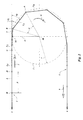
- Figure 1 shows a pitch circle 2 of a sprocket.
- the pitch circle 2 has a pitch circle radius r.
- a chain 1 in a first position indicated with a continuous line, has linkplates L, L 0 , L 1 , L 2 and L 3 ; part of the chain 1 is looped around the sprocket.
- the chain 1 comprises in longitudinal direction alternating inner linkplates and outer linkplates. Hinges with a hinge centre A, B, C, D or H couple the successive linkplates, the distance between the successive hinge centres is a pitch p.
- the pitch p and the number of teeth of the sprocket determine the pitch circle radius r and the number of teeth of the sprocket determines a pitch angle ⁇ .
- the pitch angle ⁇ is the angle between two adjacent hinge centres on the pitch circle 2 measured from a centre M of the sprocket.
- rollers or bushes Around the hinges between the inner linkplates there are rollers or bushes (not shown) that have the hinge centres A, B, C, D, H as rotation axes so that a tooth of the sprocket can fit between the inner linkplates and the rollers or bushes.
- the teeth of the sprocket can exert via the roller or bush and the hinge a force on the linkplates L, L 0 , L 1 , L 2 and L 3 .
- the rollers or bushes around the hinges form together with the inner linkplates an inner link; two outer linkplates connect the inner links.
- Such chains are available in many designs as bush chains or roller chains.
- the sprocket is indicated as having teeth that exert a force on the chain. It will be clear that this description of the invention is also applicable for chains that cooperate with sprockets that have cavities or other means to exert forces on the rollers or bushes, or on the linkplates of the chain.
- the hinge centres A, B and C are on the pitch circle 2 of a sprocket, which means that linkplates L 0 , L 1 and L 2 have a fixed position relative to the sprocket and the sprocket fully supports the linkplates.
- the chain 1 has a chain load 5 that pulls the chain 1 in a straight line in line with or parallel to a tangent 3 to the pitch circle 2.
- a radius vector 4 extends from the sprocket centre M perpendicular on the tangent 3.
- the hinge centre C is on the pitch circle 2 and on the tangent 3 and the linkplates L 3 and L extend along the tangent 3.
- the linkplate L 2 that is the last linkplate fully supported on the sprocket, makes an angle ⁇ 1 , with the common centreline of all linkplates that are not supported on the sprocket.
- an interrupted line indicates the chain 1' in a second rotative position of the sprocket after the sprocket rotated over half of the pitch angle ⁇ .
- the hinge centre C moved in a direction 9 along the pitch circle 2 to a position C'. Due to the chain load 5 in line with or parallel to tangent 3, the vertical position of the hinge centres D, H equals the vertical position of C.
- the line of small circles indicates the path of the unsupported hinge centres D and H during rotation of the sprocket.
- the linkplate L 2 rotates with the sprocket to a first angle ⁇ ' 1 with the common centre-line and the linkplates L 3 remains parallel to the tangent 3 or the common centre-line.
- the interrupted line and the full line illustrate the extreme positions of the chain 1 during rotation of the sprocket and indicate the amplitude of the path of the hinge centres.
- the linkplate L' 3 now has a fixed position relative to the sprocket and is fully supported on the sprocket and its centreline starts making a first angle ⁇ 1 with the tangent 3 and the first angle ⁇ 1 increases from 0 to the pitch angle ⁇ .
- Figure 2 shows a first embodiment of a chain 1 with internal guide means.
- the linkplate L 1 has both hinge centres A and B fully supported on the sprocket.
- the internal guide means which are elucidated hereafter, force the linkplate L 1 , when it rotates with the sprocket and makes a first angle ⁇ 1 relative a common centreline of all following unsupported linkplates, to rotate the linkplate L 2 .
- the linkplate L 2 rotates around the hinge centre B that is supported on the sprocket and has a second angle ⁇ 2 relative to the common centreline.
- the forced rotation of linkplate L 2 is designed such that during rotation of the sprocket in the direction of rotation 9 the hinge centre C and with that all following hinge centres D, H, are forced to follow the tangent 3. At the location where the tangent 3 meets the pitch circle 2 in a point of contact at the end of a radius vector 4, these hinge centres C, D, H will start to move along the pitch circle 2. This means that the bush or roller around the hinge centres C, D, H do not collide onto the sprocket but the internal guide means guide the hinge centres C, D, H towards and on the pitch circle 2 of the sprocket.
- the internal guide means acts between linkplates that are in the same plane. This means that the internal guide means acts either between inner linkplates or between outer linkplates.
- the internal guide means acts between the linkplate L 1 that has a fixed position relative to the sprocket, and the linkplate L 3 that has no fixed position relative to the sprocket.
- the linkplate L 2 couples the linkplate L 1 and linkplate L 3 with hinges that have hinge centres B and C respectively.
- the hinge centre B of linkplate L 2 is on the pitch circle 2 of the sprocket and its hinge centre C is free to move in an arc in respect to the hinge centre B on the sprocket so that linkplate L 2 has one degree of freedom.
- the centre line of the linkplate L 1 makes a first angle ⁇ 1 with the common centreline of all following unsupported linkplates and the centre line of linkplate L 2 makes a second angle ⁇ 2 with the common centre-line of all following unsupported linkplates.
- the internal guide means between linkplate L 1 and L 3 determines the second angle ⁇ 2 in dependence of the first angle ⁇ 1 . In this way the internal guide means between linkplate L 1 and linkplate L 3 determines the position of the hinge centre C and with that also the path of the hinge centres D, H prior to reaching pitch circle 2 during rotation of the sprocket.
- the second angle ⁇ 2 When the first angle ⁇ 1 is equal to 0.5 times the pitch angle ⁇ , which is the first rotative position where the linkplate L 1 is fully supported on the sprocket, the second angle ⁇ 2 will be approximately zero, as the chain load 5 pulls the linkplate L 2 in the direction of the tangent 3.
- the internal guide means force the second angle ⁇ 2 to increase from zero to approximately 0.5 times the pitch angle ⁇ .
- the first angle ⁇ 1 is equal to the pitch angle ⁇ the second angle ⁇ 2 has increased. In the shown embodiment the angle increased to at least 0.1 times the pitch angle ⁇ .
- each linkplate L, L 1 , L 2 , L 3 has at a front side 23 a front cam 18; the front cam 18 is on the most forward side of the linkplate seen in the direction of movement 7 of the chain. Also each linkplate L, L 1 , L 2 , L 3 has at a rear side 24 a rear cam 15 (see figure 6 ).
- the interactions of the front cam 18 at the front of the linkplate L 3 and the rear cam 15 at the rear of the linkplate L 1 form the internal guide means.
- the linkplate L 3 with the front cam 18 and the linkplate L 1 with the rear cam 15 are in the same plane at one side of the linkplate L 2 so that they can interact on each other.
- the rear cam 15 forces the rotation of the linkplate L 2 by having the front cam 18 pressing in a contact point Q (see figure 7 ) against the rear cam 15. This contact point Q changes for each first angle ⁇ 1 , exerts a force on the front cam 18 and forces linkplate L 2 to rotate and determines the second angle ⁇ 2 .
- an instantaneous pole 10 on the radius vector 4 indicates the point where linkplate L 1 , which is on the sprocket and which rotates around the sprocket centre M in a rotation direction 9, has a zero velocity relative to linkplate L 3 that moves in a direction 7.
- This instantaneous pole 10 has different positions for the different rotative positions of the sprocket, which means for the different values of the first angle ⁇ 1 .
- a polar curve 11 shown in figure 4 is a curve showing all instantaneous poles 10, which means for all values of the first angle ⁇ 1 , relative to linkplate L 1 seen from linkplate L 3 .
- the polar curve 11 is between forward hinge centre C of linkplate L 3 and a position 22 where the instantaneous pole 10 is at the rotative position of the sprocket whereon linkplate L 1 starts supporting linkplate L 3 and the first angle ⁇ 1 is 0.5 times the pitch angle ⁇ .
- a polar curve 12 shown in figure 5 is a curve showing all instantaneous poles 10 relative to linkplate L 3 seen from linkplate L 1 .
- the polar curve 12 is between rear hinge centre B of linkplate L 1 and a position 14 where the instantaneous pole 10 is at the rotative position of the sprocket whereon linkplate L 1 ends supporting linkplate L 3 and the sprocket fully supports the linkplate L 3 .
- Figure 6 shows the polar curve 11 at the linkplate front side 23 and polar curve 12 at the linkplate rear side 24 of a linkplate L respectively.
- Polar curve 11 determines the shape of the front cam 18
- polar curve 12 determines the shape of the rear cam 15.
- the front cam 18 is designed such, that in each point 19 on the front cam 18 there is perpendicular 20 on the front cam 18 that intersects the polar curve 11 in an instantaneous pole 21.
- Position 22, and the front hinge centre H determine the start 28 and finish 29 of the active part of the front cam 18.
- the rear hinge centre H and position 14 determine the start 26 and finish 27 of the active part of the rear cam 15. For each position on the polar curve 11, there is corresponding position on the polar curve 12. In this way by choosing one of the cams 15, 18 the other cam can be determined. This determining of the one cam using the shape of the other is done mathematically in the way described above or it can be done by generating the one cam numerically or graphically from the other.
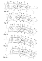
- Figure 7 shows the linkplates L 1 , L 2 and L 3 of a first embodiment as they start rotating around a sprocket with a pitch circle 2 that has a radius r.
- the linkplates are designed for cooperating with the sprocket that has 20 teeth.
- the hinge centres A and B of linkplate L 1 are on the pitch circle 2 so that a tooth space of the sprocket positions rollers or bushes 25 of the chain that are indicated by circular interrupted lines.
- the hinge centres C and D of linkplate L 3 are on the tangent 3.
- the linkplate L 2 has the hinge centres B and C that are on the tangent 3 and the hinge centre B is also on the pitch circle 2 at the end of the radius vector 4 (not shown).
- the linkplate L 2 and linkplate L 3 have a common centre line, which is the centreline of all linkplates that approach the sprocket.
- the centre lines s of linkplate L 2 which has the same direction as the common centreline, and linkplate L 1 make a first angle ⁇ 1 that is equal to 0.5 times the pitch angle ⁇ .
- the front cam 18 of linkplate L 3 touches the rear cam 15 of linkplate L 1 in contact point Q.
- Figure 7b shows the situation after the sprocket has rotated further and the first angle ⁇ 1 with the common centreline is approximately 0.75 times the pitch angle ⁇ and wherein the hinge centre B is no longer on the tangent 3.
- the linkplate L 2 makes a second angle ⁇ 2 with the common centreline.
- the contact point Q has shifted along the rear cam 15 and the front cam 18 and the interaction between the rear cam 15 and the front cam 18 lifts the hinge centre C so that the hinge centre C remains on the tangent 3 and is no longer on the same level as the hinge centre B.
- Figure 7c shows the situation where the sprocket has rotated further and the first angle ⁇ 1 with the common centreline is approximately 1.0 times the pitch angle ⁇ .
- Figure 7d shows the situation where the sprocket has rotated further and the first angle ⁇ 1 with the common centreline is approximately 1.25 times the pitch angle ⁇ .
- Figure 7e shows the situation where the sprocket has rotated further and is the first angle ⁇ 1 with the common centreline is approximately 1.5 times the pitch angle ⁇ .
- the linkplate L 2 is in the same position as the linkplate L 1 in figure 7a , and the centreline of the linkplate L 2 makes the second angle ⁇ 2 with the common centreline, which second angle ⁇ 2 is equal to 0.5 times the pitch angle ⁇ .
- the hinge centre C moves along tangent 3 as the front cam 18 of linkplate L 3 is supported by the rear cam 15 of linkplate L 1 until the ring or bush 25 surrounding hinge centre C is supported by the sprocket as shown in figure 7e .
- the sprocket After further rotation, the sprocket fully supports the linkplate L 2 and the same sequence repeats for the next hinge centre D.
- Figure 8 shows a second embodiment with an adapted linkplate L that is similar to linkplates of figure 7 .
- Figure 8 also illustrates the active part of the front cam 18 limited by the start 28 and the finish 29.
- the active part of the rear cam 15 shows the start 26 and the finish 27.
- the linkplate L comprises two hinge centres 32 at the pitch distance p.
- a line s indicates the longitudinal axis of the linkplate L.
- the rear cam 15 Immediately adjacent to the start 26 of the rear cam 15 the rear cam 15 has a circular section 31 around the rear hinge centre with an arc of 0.5 times the pitch angle ⁇ .
- an uninterrupted line in the rear cam 15 shows the recess 30 and an interrupted line in the front cam 18 shows the recess 30'.
- the recesses 30 or 30' can be in one or in both cams 15, 18. This small recess 30, 30' adds additional play in the situation where the link axes s form the common line. As soon as the linkplates L are no longer in line the front cam 18 touches the rear cam 15 as described earlier.
- the linkplate L shown in figure 8 is from material that extends at least a distance r c1 or r c2 from the hinge centre 32. This distance r c1 or r c2 is a measure for the strength of the linkplate L, as it determines the smallest load-bearing section of the linkplate L.
- the front cam 18 has a convex surface directed towards the sprocket around which it can be looped. Preferably, fillets R that have a minimum radius of approximately 0.3 mm, round off the circumference of the linkplate L where necessary, so that the linkplate L can be stamped from plate material using stamping dies that have acceptable wear resistance.
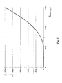
- line 33 which is the lowest line, shows the path of the hinge centres 32 of the chain with internal guide means.
- the hinge centres 32 approach the sprocket along the common centreline which in this case is the same as the tangent 3 and reach the pitch circle at the location of the radius vector 4. After the hinge centres 32 have passed the radius vector 4, they follow the pitch circle with the radius r of the sprocket as the sprocket rotates around its sprocket centre M.
- the interrupted line 34 indicates the path that the hinge centres 32 would have taken if the chain would have no internal guide means, as is the case in traditional bush or roller chains.
- the hinge centres 32 follow a path that follows the pitch circle with a radius r' before the hinge centre 32 has passed the radius vector 4. Due to the increased number of teeth, the radius r' is larger than the radius r. Before the hitch centres 32 reach the pitch circle, the hitch centres 32 follow a straight path that deviates slightly from the tangent 3.
- the interrupted line 34' indicates the path that the hinge centres 32 would have taken if the chain would have no internal guide means.
- This path is an arc with a radius r' that is equal to the pitch circle and the arc is tangent to the tangent 3.
- the figure shows that the internal guide means supports the hinge centres 32 before they reach the pitch circle and lifts the hinge centres 32 above the path that the hinge centres 32 would have taken if there is no internal guide means.
- the internal guide means lifts the unsupported hinge centre 32 as it approaches but before it reaches the sprocket. This shows that the hinge centres 32 do not impact on the sprocket, but are guided by the internal guide means towards the sprocket.
- the hinge centres 32 follow a path that follows the pitch circle with a radius r" before the hinge centre 32 has passed the radius vector 4. Due to the high number of teeth, the radius r" is larger than the radii r and r'.
- the hitch centres 32 follow an arc with a radius r" that is tangent to the tangent 3 and that changes near its lowest point in the straight line.
- the interrupted line 34" indicates the path that the hinge centres 32 would have taken if the chain would have no internal guide means.
- the internal guide means supports the hinge centres 32 for a short distance before they reach the pitch circle and lifts the hinge centres 32 above the path that the hinge centres 32 would have taken if there were no internal guide means.
- the internal guide means lifts the unsupported hinge centre 32 as it approaches but before it reaches the sprocket. This shows that the hinge centres 32 do not impact on the sprocket, but are guided by the internal guide means towards the sprocket.
- Figure 10 shows a fourth embodiment of a linkplate L.
- the linkplate L is suitable for a sprocket with 6 teeth, such a sprocket is suitable for use in chain transmission with a high transmission ratio.
- the front cam 18 has a convex surface directed towards the sprocket around which it can be looped.
- One of the longitudinal sides of the linkplate L is a straight line 41 that is parallel to the link centreline s. During production of the linkplates L, the straight line 41 is used for dimensional control.
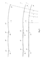
- Figure 11 shows a chain transmission with a small sprocket with a pitch circle 35 and a larger sprocket with a pitch circle 36.
- the small sprocket has six teeth and the larger sprocket has twelve teeth.
- the chain 1 looped around both sprockets has linkplates L that are similar to the linkplate L of figure 10 .
- the chain moves in a direction 39 and the sprockets rotate in a direction 40.
- the figure shows that the second following linkplate L 3 that approaches the fully supported linkplate L 1 on the smaller sprocket have a first contact 37.
- Figure 12 shows a fourth embodiment of linkplate L.
- the linkplate L is suitable for a sprocket with fourteen teeth.
- the rear cam 15 is a straight line that is perpendicular to the centreline s of the linkplate L.
- the start 26 of the rear cam 15 is on the centreline s.
- One or both longitudinal sides form straight sides 41. In this way, the production and dimensional control of the linkplate L is easy.
- Figure 13 shows a fifth embodiment of linkplate L.
- this linkplate has the bottom side of the linkplate L of figure 12 , and the bottom side of this linkplate is mirrored to the upper side, whereby the link centreline s forms the line of symmetry m.
- the link centreline s forms the line of symmetry m.
- a fillet 42 is added to prevent sharp corners in the cam 18.
- the loss of part of the front cam leads to a small but acceptable deviation in the straight path of the hinge centres 32, when they approach the sprockets.
- the advantage of this embodiment is that the chain now can bend around sprockets on both sides of the chain.
- Figure 14 shows the chain 1 around the first sprocket 47 with the direction of rotation 43 and the second sprocket 46 with a counter rotation 45.
- the sprockets 46 and 47 are on opposite sides of the chain 1 that moves in a direction 44.
Landscapes
- Engineering & Computer Science (AREA)
- General Engineering & Computer Science (AREA)
- Mechanical Engineering (AREA)
- Devices For Conveying Motion By Means Of Endless Flexible Members (AREA)
- Transmissions By Endless Flexible Members (AREA)
- Gears, Cams (AREA)
Priority Applications (2)
| Application Number | Priority Date | Filing Date | Title |
|---|---|---|---|
| EP09166643A EP2280187A1 (fr) | 2009-07-28 | 2009-07-28 | Chaîne et transmission par chaîne |
| PCT/EP2010/059679 WO2011012410A1 (fr) | 2009-07-28 | 2010-07-06 | Chaîne et transmission à chaîne |
Applications Claiming Priority (1)
| Application Number | Priority Date | Filing Date | Title |
|---|---|---|---|
| EP09166643A EP2280187A1 (fr) | 2009-07-28 | 2009-07-28 | Chaîne et transmission par chaîne |
Publications (1)
| Publication Number | Publication Date |
|---|---|
| EP2280187A1 true EP2280187A1 (fr) | 2011-02-02 |
Family
ID=41413369
Family Applications (1)
| Application Number | Title | Priority Date | Filing Date |
|---|---|---|---|
| EP09166643A Withdrawn EP2280187A1 (fr) | 2009-07-28 | 2009-07-28 | Chaîne et transmission par chaîne |
Country Status (2)
| Country | Link |
|---|---|
| EP (1) | EP2280187A1 (fr) |
| WO (1) | WO2011012410A1 (fr) |
Cited By (3)
| Publication number | Priority date | Publication date | Assignee | Title |
|---|---|---|---|---|
| GB2521916A (en) * | 2013-11-29 | 2015-07-08 | Tsubakimoto Chain Co | Chain and chain guide plate |
| KR20170096951A (ko) * | 2016-02-17 | 2017-08-25 | 가부시기가이샤쯔바기모도체인 | 체인 |
| US11840401B2 (en) | 2021-07-21 | 2023-12-12 | Forjas Bolivar S.A.S. | Plate chain with self-supported mechanism |
Families Citing this family (4)
| Publication number | Priority date | Publication date | Assignee | Title |
|---|---|---|---|---|
| USD731569S1 (en) | 2012-07-24 | 2015-06-09 | Nordischer Maschinenbau Rud. Baader Gmbh + Co. Kg | Sprocket for chain link |
| USD734590S1 (en) | 2012-07-24 | 2015-07-14 | Nordischer Maschinenbau Rud. Baader Gmbh + Co. Kg | Chain link |
| DE102012106708A1 (de) | 2012-07-24 | 2014-10-30 | Nordischer Maschinenbau Rud. Baader Gmbh + Co. Kg | Kettenglied, Stützkette und Stützvorrichtung |
| CN117113731B (zh) * | 2023-10-24 | 2024-02-09 | 北京中望数字科技有限公司 | 一种仿真链传动的方法、装置、设备及存储介质 |
Citations (3)
| Publication number | Priority date | Publication date | Assignee | Title |
|---|---|---|---|---|
| EP0494670A1 (fr) * | 1991-01-09 | 1992-07-15 | Shimano Inc. | Chaîne de bicyclette |
| EP1801453A1 (fr) * | 2005-12-22 | 2007-06-27 | Theodorus Henricus Johannes Carolina Korse | Transmission par chaîne |
| EP1843061A1 (fr) * | 2006-04-05 | 2007-10-10 | IAV GmbH Ingenieurgesellschaft Auto und Verkehr | Chaîne pour un entraînement de chaîne |
-
2009
- 2009-07-28 EP EP09166643A patent/EP2280187A1/fr not_active Withdrawn
-
2010
- 2010-07-06 WO PCT/EP2010/059679 patent/WO2011012410A1/fr not_active Ceased
Patent Citations (3)
| Publication number | Priority date | Publication date | Assignee | Title |
|---|---|---|---|---|
| EP0494670A1 (fr) * | 1991-01-09 | 1992-07-15 | Shimano Inc. | Chaîne de bicyclette |
| EP1801453A1 (fr) * | 2005-12-22 | 2007-06-27 | Theodorus Henricus Johannes Carolina Korse | Transmission par chaîne |
| EP1843061A1 (fr) * | 2006-04-05 | 2007-10-10 | IAV GmbH Ingenieurgesellschaft Auto und Verkehr | Chaîne pour un entraînement de chaîne |
Cited By (7)
| Publication number | Priority date | Publication date | Assignee | Title |
|---|---|---|---|---|
| GB2521916A (en) * | 2013-11-29 | 2015-07-08 | Tsubakimoto Chain Co | Chain and chain guide plate |
| GB2521916B (en) * | 2013-11-29 | 2016-04-13 | Tsubakimoto Chain Co | Chain and chain guide plate |
| KR101772450B1 (ko) | 2013-11-29 | 2017-08-30 | 가부시기가이샤쯔바기모도체인 | 체인 및 체인용 가이드 플레이트 |
| US9803720B2 (en) | 2013-11-29 | 2017-10-31 | Tsubakimoto Chain Co. | Chain and chain guide plate |
| KR20170096951A (ko) * | 2016-02-17 | 2017-08-25 | 가부시기가이샤쯔바기모도체인 | 체인 |
| KR102009553B1 (ko) | 2016-02-17 | 2019-08-09 | 가부시기가이샤쯔바기모도체인 | 체인 |
| US11840401B2 (en) | 2021-07-21 | 2023-12-12 | Forjas Bolivar S.A.S. | Plate chain with self-supported mechanism |
Also Published As
| Publication number | Publication date |
|---|---|
| WO2011012410A1 (fr) | 2011-02-03 |
Similar Documents
| Publication | Publication Date | Title |
|---|---|---|
| EP2280187A1 (fr) | Chaîne et transmission par chaîne | |
| US8157683B2 (en) | Chain for a chain transmission | |
| KR101659605B1 (ko) | 소팅 컨베이어 | |
| EP1054825B1 (fr) | Dispositif de manutention | |
| RU2438054C1 (ru) | Приводное средство и цепной привод | |
| US7690497B2 (en) | Transfer device for the lateral ejection of transported goods and transport unit | |
| US4232783A (en) | Step link for transportation apparatus | |
| US20110306452A1 (en) | Chain transmission mechanism | |
| TW201544732A (zh) | 3d推拉式鍊條 | |
| JP4122288B2 (ja) | 歩行者用コンベアシステムの逆転装置領域においてリンクプレートチェーンを案内する方法 | |
| EP2331445B1 (fr) | Dispositif de transfert de personnes, chaîne de transmission et procédé dans l'utilisation d'un dispositif de transfert de personnes | |
| EP1897837B1 (fr) | Chariot à roues motrices avant et arrière | |
| US7107754B2 (en) | Chain in particular a hoist chain | |
| CN101855473A (zh) | 动力传动链 | |
| JP2002227948A (ja) | バリエータ | |
| US10619705B2 (en) | Belt means and system for constructing a belt means | |
| EP3257793B1 (fr) | Courroie de transporteur | |
| EP0420907B1 (fr) | Transporteur a bande | |
| CZ176195A3 (en) | Driving system for arc-shape escalator | |
| MX2007009682A (es) | Portador para ascensor para un sistema de ascensores, el sistema de ascensores con tal portador para ascensor y procedimiento para el montaje de ese sistema de ascensores. | |
| KR101917539B1 (ko) | 트롤리 체인의 센터 링크 및 그 센터 링크를 포함한 트롤리 | |
| JP5261719B2 (ja) | リンクプレートチェーン | |
| CN107687505B (zh) | 链条传动装置 | |
| EP3144560A1 (fr) | Entraînement à chaîne | |
| TW202030116A (zh) | 驅動鏈條系統 |
Legal Events
| Date | Code | Title | Description |
|---|---|---|---|
| PUAI | Public reference made under article 153(3) epc to a published international application that has entered the european phase |
Free format text: ORIGINAL CODE: 0009012 |
|
| AK | Designated contracting states |
Kind code of ref document: A1 Designated state(s): AT BE BG CH CY CZ DE DK EE ES FI FR GB GR HR HU IE IS IT LI LT LU LV MC MK MT NL NO PL PT RO SE SI SK SM TR |
|
| AX | Request for extension of the european patent |
Extension state: AL BA RS |
|
| STAA | Information on the status of an ep patent application or granted ep patent |
Free format text: STATUS: THE APPLICATION IS DEEMED TO BE WITHDRAWN |
|
| 18D | Application deemed to be withdrawn |
Effective date: 20110803 |