EP2280189A2 - Automatikgetriebe - Google Patents
Automatikgetriebe Download PDFInfo
- Publication number
- EP2280189A2 EP2280189A2 EP10171347A EP10171347A EP2280189A2 EP 2280189 A2 EP2280189 A2 EP 2280189A2 EP 10171347 A EP10171347 A EP 10171347A EP 10171347 A EP10171347 A EP 10171347A EP 2280189 A2 EP2280189 A2 EP 2280189A2
- Authority
- EP
- European Patent Office
- Prior art keywords
- frictional element
- speed
- frictional
- gear
- clutch
- Prior art date
- Legal status (The legal status is an assumption and is not a legal conclusion. Google has not performed a legal analysis and makes no representation as to the accuracy of the status listed.)
- Granted
Links
- 230000005540 biological transmission Effects 0.000 title claims abstract description 120
- 230000000052 comparative effect Effects 0.000 description 23
- 230000009471 action Effects 0.000 description 9
- 239000000446 fuel Substances 0.000 description 9
- 230000012447 hatching Effects 0.000 description 8
- 230000001133 acceleration Effects 0.000 description 6
- 238000010572 single replacement reaction Methods 0.000 description 6
- 238000004519 manufacturing process Methods 0.000 description 4
- 230000004048 modification Effects 0.000 description 4
- 238000012986 modification Methods 0.000 description 4
- 230000009467 reduction Effects 0.000 description 4
- 230000004044 response Effects 0.000 description 4
- 230000001174 ascending effect Effects 0.000 description 3
- 230000008878 coupling Effects 0.000 description 3
- 238000010168 coupling process Methods 0.000 description 3
- 238000005859 coupling reaction Methods 0.000 description 3
- 230000006872 improvement Effects 0.000 description 3
- 238000004513 sizing Methods 0.000 description 2
- 238000001816 cooling Methods 0.000 description 1
- 230000003247 decreasing effect Effects 0.000 description 1
- 230000003111 delayed effect Effects 0.000 description 1
- 238000011156 evaluation Methods 0.000 description 1
- 238000005461 lubrication Methods 0.000 description 1
- 238000012423 maintenance Methods 0.000 description 1
- 230000007246 mechanism Effects 0.000 description 1
- 230000007704 transition Effects 0.000 description 1
Images




Classifications
-
- F—MECHANICAL ENGINEERING; LIGHTING; HEATING; WEAPONS; BLASTING
- F16—ENGINEERING ELEMENTS AND UNITS; GENERAL MEASURES FOR PRODUCING AND MAINTAINING EFFECTIVE FUNCTIONING OF MACHINES OR INSTALLATIONS; THERMAL INSULATION IN GENERAL
- F16H—GEARING
- F16H3/00—Toothed gearings for conveying rotary motion with variable gear ratio or for reversing rotary motion
- F16H3/44—Toothed gearings for conveying rotary motion with variable gear ratio or for reversing rotary motion using gears having orbital motion
- F16H3/62—Gearings having three or more central gears
- F16H3/66—Gearings having three or more central gears composed of a number of gear trains without drive passing from one train to another
- F16H3/666—Gearings having three or more central gears composed of a number of gear trains without drive passing from one train to another with intermeshing orbital gears
-
- F—MECHANICAL ENGINEERING; LIGHTING; HEATING; WEAPONS; BLASTING
- F16—ENGINEERING ELEMENTS AND UNITS; GENERAL MEASURES FOR PRODUCING AND MAINTAINING EFFECTIVE FUNCTIONING OF MACHINES OR INSTALLATIONS; THERMAL INSULATION IN GENERAL
- F16H—GEARING
- F16H3/00—Toothed gearings for conveying rotary motion with variable gear ratio or for reversing rotary motion
- F16H3/44—Toothed gearings for conveying rotary motion with variable gear ratio or for reversing rotary motion using gears having orbital motion
- F16H3/62—Gearings having three or more central gears
-
- F—MECHANICAL ENGINEERING; LIGHTING; HEATING; WEAPONS; BLASTING
- F16—ENGINEERING ELEMENTS AND UNITS; GENERAL MEASURES FOR PRODUCING AND MAINTAINING EFFECTIVE FUNCTIONING OF MACHINES OR INSTALLATIONS; THERMAL INSULATION IN GENERAL
- F16H—GEARING
- F16H2200/00—Transmissions for multiple ratios
- F16H2200/003—Transmissions for multiple ratios characterised by the number of forward speeds
- F16H2200/006—Transmissions for multiple ratios characterised by the number of forward speeds the gear ratios comprising eight forward speeds
-
- F—MECHANICAL ENGINEERING; LIGHTING; HEATING; WEAPONS; BLASTING
- F16—ENGINEERING ELEMENTS AND UNITS; GENERAL MEASURES FOR PRODUCING AND MAINTAINING EFFECTIVE FUNCTIONING OF MACHINES OR INSTALLATIONS; THERMAL INSULATION IN GENERAL
- F16H—GEARING
- F16H2200/00—Transmissions for multiple ratios
- F16H2200/0082—Transmissions for multiple ratios characterised by the number of reverse speeds
- F16H2200/0086—Transmissions for multiple ratios characterised by the number of reverse speeds the gear ratios comprising two reverse speeds
-
- F—MECHANICAL ENGINEERING; LIGHTING; HEATING; WEAPONS; BLASTING
- F16—ENGINEERING ELEMENTS AND UNITS; GENERAL MEASURES FOR PRODUCING AND MAINTAINING EFFECTIVE FUNCTIONING OF MACHINES OR INSTALLATIONS; THERMAL INSULATION IN GENERAL
- F16H—GEARING
- F16H2200/00—Transmissions for multiple ratios
- F16H2200/20—Transmissions using gears with orbital motion
- F16H2200/2002—Transmissions using gears with orbital motion characterised by the number of sets of orbital gears
- F16H2200/201—Transmissions using gears with orbital motion characterised by the number of sets of orbital gears with three sets of orbital gears
-
- F—MECHANICAL ENGINEERING; LIGHTING; HEATING; WEAPONS; BLASTING
- F16—ENGINEERING ELEMENTS AND UNITS; GENERAL MEASURES FOR PRODUCING AND MAINTAINING EFFECTIVE FUNCTIONING OF MACHINES OR INSTALLATIONS; THERMAL INSULATION IN GENERAL
- F16H—GEARING
- F16H2200/00—Transmissions for multiple ratios
- F16H2200/20—Transmissions using gears with orbital motion
- F16H2200/203—Transmissions using gears with orbital motion characterised by the engaging friction means not of the freewheel type, e.g. friction clutches or brakes
- F16H2200/2046—Transmissions using gears with orbital motion characterised by the engaging friction means not of the freewheel type, e.g. friction clutches or brakes with six engaging means
-
- F—MECHANICAL ENGINEERING; LIGHTING; HEATING; WEAPONS; BLASTING
- F16—ENGINEERING ELEMENTS AND UNITS; GENERAL MEASURES FOR PRODUCING AND MAINTAINING EFFECTIVE FUNCTIONING OF MACHINES OR INSTALLATIONS; THERMAL INSULATION IN GENERAL
- F16H—GEARING
- F16H2200/00—Transmissions for multiple ratios
- F16H2200/20—Transmissions using gears with orbital motion
- F16H2200/203—Transmissions using gears with orbital motion characterised by the engaging friction means not of the freewheel type, e.g. friction clutches or brakes
- F16H2200/2048—Transmissions using gears with orbital motion characterised by the engaging friction means not of the freewheel type, e.g. friction clutches or brakes with seven engaging means
Definitions
- the present invention relates to an automatic transmission which is suitable as a vehicular transmission mechanism for which multi-stage demand of gear shift stages and widening demand of a gear ratio width are present.
- a Japanese Patent Application First Publication No. 2001-182785 published on July 6, 2001 exemplifies a previously proposed automatic transmission achieving respective gear shift stages of eight forward speeds (speed ratios) by means of three planetary gearsets and six frictional elements and which is provided with a double pinion planetary gearset, a Ravineaux planetary gear unit (one double pinion planetary gearset and one single pinion planetary gearset), four clutches, and two brakes.
- an object of the present invention to provide an automatic transmission which is capable of improving the transmission efficiency of the drive energy by suppressing the frictional loss to be reduced while achieving the eight forward speeds with the three planetary gearset and six frictional elements.
- an automatic transmission comprising: a first planetary gearset (PG1) including a first sun gear (51), a first ring gear (R1), and a first carrier (PC1) supporting a first double pinion (P1s, P1r) meshed with the first sun gear and the first ring gear; a second planetary gearset (PG2) including a second sun gear (S2), a second carrier (PC2) supporting a second pinion (P2) meshed with the second sun gear, and a second ring gear (R3) meshed with the second pinion; a third planetary gearset (PG3) including a third sun gear (S3), a third carrier (PC3) supporting a third pinion (P3) meshed with the third sun gear, and a third ring gear (R3) meshed with the third pinion, the first sun gear and the second sun gear being at all times linked together to constitute a first rotary member (M1) and the second ring gear and the third sun gear being at all times linked together to constitute a first rotary member (M1) and the second
- Fig. 1 is a skeleton view representing an automatic transmission in a first preferred embodiment according to the present invention.
- Fig. 2 is a table representing engagement operations achieving eight forward speeds and one reverse speed by a combination of simultaneous engagements of three frictional elements from among six frictional elements.
- Fig. 3 is a plotted graph representing a variation characteristic of a step ratio which is a gear ratio variation rate at adjacent gear shift stages of eight forward speeds in the automatic transmission in the first preferred embodiment.
- Fig. 4 is an explanatory view of a gear shift section at a first speed gear shift stage (1-st speed) in the automatic transmission of the first preferred embodiment.
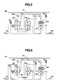
- Fig. 5 is an explanatory view of the gear shift section at a second gear shift stage (2-nd speed) in the automatic transmission of the first preferred embodiment.
- Fig. 6 is an explanatory view of the gear shift section at a third gear shift stage (3-rd speed) in the automatic transmission of the first preferred embodiment.
- Fig. 7 is an explanatory view of the gear shift section at a fourth gear shift stage (4-th speed) in the automatic transmission of the first preferred embodiment.
- Fig. 8 is an explanatory view of the gear shift section at a fifth gear shift stage (5-th speed) in the automatic transmission of the first preferred embodiment.
- Fig. 9 is an explanatory view of the gear shift section at a sixth gear shift stage (6-th speed) in the automatic transmission of the first preferred embodiment.
- Fig. 10 is an explanatory view of the gear shift section at a seventh gear shift stage (7-th speed) in the automatic transmission of the first preferred embodiment..
- Fig. 11 is an explanatory view of the gear shift section at an eighth gear shift stage (8-th speed) in the automatic transmission of the first embodiment.
- Fig. 12 is an explanatory view of the gear shift section at a reverse (Rev) gear shift stage in the first embodiment of the automatic transmission.
- Fig. 13 is a skeleton view representing an automatic transmission of a comparative example to the automatic transmission in the first preferred embodiment.
- Fig. 14 is a table representing engagement operations achieving the eight forward speed and two reverse speeds by a combination of two simultaneous clutches of six frictional elements in the automatic transmission in the comparative example.
- Fig. 15 is a table representing engagement operations achieving the eight forward speed and one reverse speed by a combination of simultaneous engagements from among sixth frictional elements in the automatic transmission of the second preferred embodiment according to the present invention.
- Fig. 16 is an explanatory view representing a gear shift operation at the gear shift stage of the fifth speed in a case of the automatic transmission in the second preferred embodiment
- Fig. 1 shows a skeleton view representing the automatic transmission in the first preferred embodiment according to the present invention.
- structures of planetary gearsets and frictional elements will be described below on a basis of Fig. 1 .
- the automatic transmission in the first embodiment includes, as shown in Fig. 1 , a first planetary gearset PG1, a second planetary gearset PG2, a third planetary gearset PG3, an input shaft IN, an output shaft OUT, a first rotary member M1, a second rotary member M2, a first clutch C1 (a first frictional element), a second clutch C2 (a second frictional element), a third clutch (a third frictional element), a fourth clutch C4 (a fourth frictional element), a first brake B1 (a fifth frictional element), a second brake B2 (a sixth frictional element), a transmission casing TC, and a one-way clutch OWC.
- First planetary gearset PG1 is a double pinion planetary gearset having a first double pinion Pis, P1r and including a first sun gear S1, pinion P1s meshed with first sun gear S1, a first carrier PC1 supporting a pinion P1r meshed with second pinion P2, and a first ring gear R1 meshed with pinion P1r.
- Second planetary gearset PG2 includes a single pinion planetary gearset and includes a second sun gear S2, a second carrier PC2 supporting a second pinion P2 meshed with second sun gear 52, and a second ring gear R2 meshed with second pinion P2.
- Third planetary gearset PG3 is the single pinion planetary gearset and includes a third sun gear S3, a third carrier PC3 supporting a third pinion P3 meshed with third sun gear S3, and a third ring gear R3 meshed with third pinion P3.
- Input shaft IN is an axle through which a revolution drive torque from a drive source (an engine and so forth) is inputted via a torque converter and so forth and is always linked with first ring gear PC3.
- Output shaft OUT is an axle through which the revolution drive torque after the gear shift to the drive wheels via the propeller shaft and the final gear and is at all times linked with first ring gear R1.
- First revolution (rotary) member M1 is a rotary member that at all times makes first sun gear S1 link with second sun gear S2 without intervention of the frictional element.
- Second revolution (rotary) member M2 is a rotary member that at all times makes second ring gear R2 link with third sun gear 53 without any intervention of the frictional elements.
- First clutch C1 is a first frictional element which selectively links between first carrier PC1 and second carrier PC2.
- Second clutch C2 is a second frictional element which selectively links between first ring gear R1 and second carrier PC2.
- Third clutch C3 is a third frictional element which selectively links between first rotary member M1 and third carrier PC3.
- Fourth clutch C4 is a fourth frictional element which selectively links between first rotary member M1 and third ring gear R3.
- First brake B1 is a fifth frictional element which is capable of stopping in an engaged state a revolution of first carrier PC1 with respect to transmission casing TC. It should be noted that one-way clutch OWC which performs a self-release during a coasting and which performs a self-lock during a drive at a position parallel to first brake B1.
- Second brake B2 is a sixth frictional element which is capable of stopping in the engaged state a revolution of third ring gear R3 with respect to transmission casing TC.
- a longitudinal arrangement of first planetary gearset PG1, second planetary gearset PG2, and third planetary gearset PG3 is made in a sequence from input shaft IN to which the drive source is connected to output shaft OUT, as shown in Fig. 1 .
- Fig. 2 shows a table representing the engagement operations achieving eight forward speeds and one reverse speed by a combination of simultaneous engagements of three frictional elements from among six frictional elements in the automatic transmission in the first preferred embodiment.
- the gear shift structure achieving the respective gear shift stages of the automatic transmission in the first preferred embodiment according to the present invention will be described below with reference to Fig. 2 .
- Automatic transmission in the first embodiment achieves the respective gear shift stages of the eight forward speeds (speed ratios) and one reverse speed as will be described later by the combination of simultaneous engagements of three of six frictional elements C1, C2, G3, C4, B1, and B2.
- the gear shift stage of a first speed (1-st) is achieved by the simultaneous engagements of second clutch C2, first brake B1 (or a one-way clutch OWC), and a second brake B2, as shown in Fig. 2 .
- the gear shift stage of a second speed (2-nd speed) is achieved by the simultaneous engagements of first clutch C1, second clutch C2, and second brake B2, as shown in Fig. 2 .
- the gear shift stage of a third speed (3-rd speed) is achieved by the simultaneous engagements of first clutch C1, fourth clutch C4, and second brake B2, as shown in Fig. 2 .
- the gear shift stage of a fourth speed (4-th speed) is achieved by the simultaneous engagements of first clutch C1, fourth clutch C4, and second brake B2, as shown in Fig. 2 .
- the gear shift stage of a fifth speed (5-th speed) is achieved by the simultaneous engagements of first clutch C1, fourth clutch C3, and fourth clutch C4, as shown in Fig. 2 .
- the gear shift stage of a sixth speed (6-th speed) is achieved by the simultaneous engagements of first clutch C1, fourth clutch C4, and first brake B1, as shown in Fig. 2 .
- the gear shift stage of a seventh speed (7-th speed) is achieved by the simultaneous engagements of second clutch C2, fourth clutch C4, and first brake B1, as shown in Fig. 2 .
- the gear shift stage of an eighth speed (8-th speed) is achieved by the simultaneous engagements of third clutch C3, fourth clutch C4, and first brake B1.
- the gear shift stage of a reverse speed (Rev) is achieved by the simultaneous engagements of first clutch C1, first brake B1, and second brake B2, as shown in Fig. 2 .
- second clutch C2 At the gear shift stage at the first speed (1-st) (ratio), second clutch C2, one-way clutch OWC, and second brake B2 are simultaneously engaged during a driving and second clutch C2, first brake B1, and second brake B2 are simultaneously engaged during a coasting.
- the engagement of second clutch C2 causes a direct coupling of second carrier PC2 to an input shaft IN.
- first brake B1 or a self-lock of one-way clutch OWC causes first carrier PC1 to be fixed to transmission casing TC.
- second brake B2 causes third ring gear R3 to be fixed to transmission casing TC.
- first clutch C1, second clutch C2, and second brake B2 are simultaneously engaged together, as shown in hatchings of Fig. 5 .
- first clutch C1 and second clutch C2 causes three rotary members S1, PC1, R1 of first planetary gearset PG1 to be rotated together in a unit and three rotary members S2, PC2, R2 of second planetary gearset PG2 to be rotated together in a unit. Then, the engagement of second brake B2 causes third ring gear R3 to be fixed to transmission casing TC.
- the input revolution speed is inputted to first ring gear R1 via input shaft IN.
- the input revolution speed from input shaft IN is outputted from second ring gear R2 passing through first planetary gearset PG1 in an integral revolution state ⁇ first rotary member M1 ⁇ second planetary gearset PG2 in the integral revolution state.
- third planetary gearset PG3 of the ring fixture state the input revolution speed of second ring gear R2 is inputted to third ring gear S3 passing through second rotary member M2.
- the revolution speed to which the input revolution speed is decelerated is outputted from third carrier PC3
- the output revolution speed of third carrier PC3 (the deceleration revolution which is higher than the first speed although lower than the input revolution speed) is directly transmitted to output shaft OUT from third carrier PC3 to achieve the second speed gear shift stage.
- first clutch C1, third clutch C3, and second brake B2 are simultaneously engaged as shown in the hatchings of Fig. 6 .
- first clutch C1 causes first carrier PC1 and second carrier PC2 to be directly coupled together.
- third clutch C3 and first rotary member M1 permits the direct coupling among first sun gear S1, second sun gear S2, and third carrier PC3.
- second brake B2 causes third ring gear R3 to be fixed to transmission casing TC.
- the input revolution speed is inputted to first ring gear R1 passing through input shaft IN.
- the revolution speeds of second sun gear S2 and second carrier PC2 are determined in second planetary gearset PG2 of the two inputs and one output.
- the revolution speed at which the revolution speed is increased in the positive direction with respect to the input revolution speed is inputted to third sun gear S3.
- the revolution speed at which the revolution speed of second ring gear R2 is decelerated is outputted from third carrier PC3.
- the output revolution speed of third carrier PC3 (the deceleration revolution higher than the third speed but lower than the input revolution speed) is directly transmitted from third carrier PC3 to output shaft OUT to achieve the gear shift stage of the fourth speed.
- first clutch C1, second clutch C2, and fourth clutch C4 are simultaneously engaged as denoted by the hatchings in Fig. 8 .
- first clutch C1, second clutch C2, and fourth clutch C4, first rotary member M1, and second rotary member M2 cause three rotary elements S1, PC1, and R1 in first planetary gearset PG1 to be rotated together in a unit, three rotary elements S2, PC2, R2 of second planetary gearset PG2 to be rotated together in a unit, and three rotary elements S3, PC3, and R3 of third planetary gearset PG3 to be rotated together in a unit.
- the input revolution speed when the input revolution speed is inputted to first ring gear R1 passing through input shaft IN, the input revolution speed causes first planetary gearset PG1, second planetary gearset PG2, and third planetary gearset PG3 to be rotated together in a unit.
- the revolution speed of output shaft OUT becomes the same revolution speed of the input revolution speed from input shaft IN to achieve the transmission in a 1-st gear shift ratio and fifth clutching (the direct coupled gear shift).
- first clutch C1, fourth clutch C4, and first brake B1 are simultaneously engaged, as shown by the hatchings of Fig. 9 .
- the input revolution speed is inputted to first ring gear R1 passing through input shaft IN.
- the revolution speed at which the increase in the revolution speed in the positive direction with respect to the input revolution speed is outputted from first sun gear S1.
- the revolution speed of first sun gear S1 is inputted to second sun gear S2 passing through first rotary member M1.
- the revolution speed of first rotary member M1 is inputted to third ring gear R3 passing through fourth clutch C4.
- the revolution speed to which the revolution speed of second ring gear R2 is increased is outputted from third carrier PC3.
- the output revolution speed (the revolution speed higher than the input revolution speed) is directly transmitted to output shaft OUT to achieve the gear shift stage of the sixth speed.
- second clutch C2, fourth clutch C4, and first brake B1 are simultaneously engaged as shown in the hatchings of Fig. 10 .
- the engagement of second clutch C2 causes the input revolution speed to be inputted to second carrier PC2.
- the engagement of fourth clutch C4 causes the direct coupling among first sun gear S1, second sun gear S2, and third ring gear R3.
- the engagement of first brake B1 causes first carrier PC1 to be fixed to transmission casing TC.
- third planetary gearset PG3 of the two inputs and one output the revolution speed of second ring gear R2 is inputted to third sun gear S3 via second rotary member M2 and the revolution speed of first rotary member M1 is inputted to third ring gear R3 via second rotary member M2.
- the revolution speed to which revolution speed of second ring gear R2 is increased is outputted to third carrier PC3.
- the output revolution speed of this third carrier PC3 (increased speed revolution higher than the input revolution speed and the sixth speed) is directly transmitted to output shaft OUT from third carrier PC3 to achieve the gear shift stage of 7-th speed.
- third clutch C3, fourth clutch C4, and first brake B1 are simultaneously engaged as shown in the hatchings of Fig. 11 .
- third clutch C3 and fourth clutch C4, first rotary member M1, and second rotary member M2 cause three rotary elements S2, PC2, R2 in second planetary gearset PG2 to be rotated together in a unit and cause three rotary elements S3, PC3, R3 in third planetary gearset PG3 to be rotated together in a unit.
- the engagements of first brake B1 cause first carrier PC1 to be fixed to transmission casing TC.
- first ring gear R1 when the input revolution speed is inputted to first ring gear R1 via input shaft IN, the revolution speed to which the input revolution speed is increased in the positive direction with respect to the input revolution speed is outputted from first sun gear S1.
- the output revolution from first sun gear S1 is increased in the positive direction and is outputted via first rotary member M1 ⁇ second planetary gearset PG2 (integrated rotation) ⁇ second rotary member M2 ⁇ third planetary gearset PG3 (integral revolution).
- This output revolution speed (increased speed revolution higher than the input revolution speed and higher than seventh speed) is directly transmitted to output shaft OUT via third carrier PC3 to achieve the gear shift stage of the eighth speed.
- first clutch C1, first brake B1, and second brake B2 are simultaneously engaged as shown in the hatchings in Fig. 12 .
- first clutch C1 and first brake B1 causes first carrier PC1 and second carrier PC2 to be fixed to transmission casing TC.
- the engagement of second brake B2 causes third ring gear R3 to be fixed to transmission casing TC.
- Fig. 13 shows a skeleton view representing the automatic transmission in the comparative example.
- Fig. 14 shows an engagement operation table by the simultaneous engagements of two frictional elements from among six frictional elements in the automatic transmission in the comparative example shown in Fig. 13 to achieve the eight forward speeds and two reverse speeds.
- Figs. 13 and 14 show the advantages of the automatic transmission in the first embodiment as compared with the comparative example.
- the automatic transmission in the first embodiment ( Figs. 1 and 2 ) is compared with the automatic transmission in the comparative example ( Figs. 13 and 14 ). At this time, a transmission performance can be equal to each other with respect to the following points.
- Both of the automatic transmission in the first embodiment and that in the comparative example achieve the gear shift stages of the eight forward speeds and first reverse speed by means of any three planetary and six frictional elements.
- Each of both of the automatic transmission in the first embodiment and that in the comparative example achieves the gear shift to an adjacent gear shift stage by a single replacement gear shift in which a release of one of the frictional elements and an engagement of one of the other frictional elements are made.
- the automatic transmission in the first embodiment has advantages over the automatic transmission in the following listed points.
- Friction loss in each of the gear shift stages In a case where each of the gear shift stages is obtained by engaging the frictional elements, the frictional loss cannot be avoided due to a drag of one frictional element (release element) which runs idle. However, in the automatic transmission, a smaller frictional loss is preferable.
- the two frictional elements are simultaneously engaged at the respective gear shift stages as shown in Fig. 14 . Therefore, for example, the frictional elements which run idle at the first speed (range) are first clutch C1, third clutch C3, fourth clutch C4, and first brake B1. In this way, the frictional elements which run idle are four at the respective gear shift stages. Therefore, the frictional loss becomes larger due to the drag from among the four frictional elements which run idle so that the worsening of the transmission efficiency of energy is introduced. For example, in a case where the automatic transmission in the comparative example is applied to the engine mounted vehicle, the frictional loss due to the four frictional elements which run idle provides a factor for introducing the worsening of the fuel economy performance.
- the three frictional elements are simultaneously engaged at their respective shift stages as shown in Fig. 2 to achieve the respective shift stages of the eight forward speeds. Therefore, for example, the frictional elements which run idle at the first speed (range) are first clutch C1, third clutch C3, and fourth clutch C4. Thus, the frictional elements at each of the gear shift stages are three.
- the frictional loss at the frictional elements which run idle is suppressed to be small as compared with the comparative example, the improvement in the transmission efficiency of a drive energy can be made.
- the automatic transmission in the first embodiment is applied to the engine mounted vehicle, the improvement in a fuel consumption performance is achievable.
- the double pinion planetary gearset and the Ravigneaux type planetary gear unit are used. That is to say, since the two double pinion planetary gearsets are substantially used, gear diameters of the pinions are made small and such problems that an endurance reliability is reduced and the number of parts are increased, and, accordingly, a manufacturing cost is increased are raised.
- first planetary gearset PG1 of the double pinion planetary gearset, second planetary gearset, and third planetary gearset are used.
- the number of uses of the double pinion planetary gearset are reduced. Consequently, since a rigidity of each of the pinions and a strength of a tooth surface can be increased, the endurance reliability can be improved, the number of parts are decreased, the decrease in the manufacturing cost can be achieved.
- the automatic transmission for the engine mounted vehicle is mounted in an engine compartment of a limited space together with the engine. Therefore, as a size of the automatic transmission becomes smaller, the better mountability can be assured. In addition, as the weight of the automatic transmission becomes lighter, the increase in a total weight of the vehicle is suppressed and is advantageous (effective) in terms of a fuel economy.
- RC value a minimum gear shift stage gear ratio/a maximum gear shift stage gear ratio: hereinafter, referred to as RC.
- RC value can be set to a further larger value (about 60% expansion than the automatic transmission in the comparative example) so that a compatibility between a starting performance at the minimum gear shift stage gear ratio and a high-speed fuel economy at the maximum gear shift stage gear ratio can be established.
- the meaning of the appropriate step ratio is such that, in a case where the step ratio at each of the gear shift stages is plotted and a characteristic line connecting plotted points can draw a line which is dropped at a smooth gradient from a low gear shift side to a high gear shift side and, thereafter, is transited in a sidewise movement state.
- the step ratio characteristic in the automatic transmission of the first embodiment draws the characteristic line having the appropriate step ratio such that the step ratio at the low gear side is highest as shown in Fig. 3 and is reduced at a smooth gradient toward the high gear side (2-nd/3-rd, 3-rd/4-th, 4-th/5-th) and, thereafter, is transited in the sidewise movement state (4-th/5-th, 5-th/6-th, 6-th/7-th, 7-th/8-th).
- a revolution speed transmitted actually to drive wheels of roads wheels is adjusted at a final gear ratio by a final differential unit mounted at a downstream position of the automatic transmission.
- an adjustment degree of freedom by the final gear ratio becomes higher.
- gasoline engine and diesel engine having different optimum fuel economy region and highest torque region.
- both of a start driving force and the fuel economy (a low revolution of engine speed) can become compatible.
- 1-st (First speed) gear ratio and reverse gear ratio are values determining a start acceleration characteristic of the vehicle and an ascending slope (up-hill) performance of the vehicle. For example, in a case where a ratio between 1-st (first) speed gear ratio and reverse gear ratio is not placed in a vicinity to 1, a difference in the driving force occurs during a switch between forward and backward starts. In addition, if the reverse gear ratio is lower than the first-speed gear ratio, the driving force during the reverse start becomes lower than that during the forward start so that the reverse start characteristic becomes inferior.
- Rev1/1-st a level such that an insufficient driving force during the reverse (backward) movement can be prevented from occurring is maintained.
- Rev1 reverse 1-st
- Rev2 reverse second speed
- the ratio between 1-st speed gear ratio and reverse gear ratio is made lower than 1.
- An automatic transmission comprising: a first planetary gearset (PG1) including a first sun gear(S1), a first ring gear (R1), and a first carrier (PC1) supporting a first double pinion (P1s, P1r) meshed with the first sun gear and the first ring gear; a second planetary gearset (PG2) including a second sun gear (S2), a second carrier (PC2) supporting a second pinion (P2) meshed with the second sun gear, and a second ring gear(R3) meshed with the second pinion; a third planetary gearset (PG3) including a third sun gear (S3), a third carrier (PC3) supporting a third pinion (P3) meshed with the third sun gear, and a third ring gear (R3) meshed with the third pinion, the first sun gear and the second sun gear being at all times linked together to constitute a first rotary member (M1) and the second ring gear and the third ring gear being at all times linked together to constitute a second rotary member (M2);
- an improvement in the transmission efficiency of the drive energy can be made by suppressing the frictional loss to be small while achieving the eight forward speeds with the three planetary gearset and the six frictional elements.
- the endurance reliability is improved and the manufacturing cost reduction can be achieved.
- the number of linkage members passing into the inside of sun gears S1, S2, and S3 become less as compared with the automatic transmission in the comparative example, the endurance reliability is improved and the manufacturing cost reduction can be achieved.
- the drive power is outputted from third carrier PC3 whose rigidity of parts is the highest, the rigidity of output shaft OUT can be secured.
- At least eight forward speeds comprise: the first speed achieved by the simultaneous engagements of the second frictional element (second clutch (C2)), the fifth frictional element (first brake B1), and the sixth frictional element (second brake B2); the second speed achieved by the simultaneous engagements of the first frictional element (first clutch C1), the second frictional element (second clutch C2), and sixth frictional element (second brake 82); the third speed achieved by the simultaneous engagements of the first frictional element (first clutch C1), third frictional element (third clutch C3), and sixth frictional element (second brake B2); the fourth speed achieved by the simultaneous engagements of the first frictional element (first clutch C1), the fourth frictional element (fourth clutch C4), and the sixth frictional element (second brake B2); the fifth speed achieved by the simultaneous engagements of the first frictional element (first clutch C1), the second frictional element (second clutch C2), and the fourth frictional element (fourth clutch C4); the sixth speed achieved by the simultaneous
- the gear shift toward one of the adjacent shift stages is achieved by the single replacement gear shift according to the engagement of one frictional element and the release of any one of the other frictional elements.
- a gear shift control thus, can advantageously be simplified.
- the RC value can be set to a required value while maintaining the appropriate step ratio achieving the compatibility between the start performance at the minimum gear shift stage and high-speed fuel economy at the maximum gear shift stage gear ratio.
- a second preferred embodiment has the same skeleton structure as the first embodiment but the elements during the fifth speed run from among the engagement operation table are made different from the first embodiment 1.
- Fig. 15 shows a table representing the engagement operations achieving the eight forward speeds and one reverse speed by the combination of the three simultaneous engagements from among the six frictional elements in the automatic transmission in the second embodiment.
- the automatic transmission in the second embodiment achieves each of the gear shift stages of the eight forward speeds and one reverse (1-st) speed by the combination of the three simultaneous engagements from among six frictional elements C1, C2, C3, C4, B1, and B2, as described below.
- the gear shift stage of the first speed (1-st) is achieved by the simultaneous engagements of second clutch C2, first brake B1 (or one-way clutch OWC), and second brake B2, as shown in Fig. 15 .
- the gear shift stage of the second speed (2-nd) is achieved by the simultaneous engagements of first clutch C1, second clutch C2, and second brake B2, as shown in Fig. 15 .
- the gear shift stage of the third speed (3-rd) is achieved by the simultaneous engagements of first clutch C1, third clutch C3, and second brake B2, as shown in Fig. 15 .
- the gear shift stage of the fourth speed (4-th) is achieved by the simultaneous engagements of first clutch C1, fourth clutch C4, and second brake B2, as shown in Fig. 15 .
- the gear shift stage of the fifth speed (5-th) is achieved by the simultaneous engagements of first clutch C1, third clutch C3, and fourth clutch C4, as shown in Fig. 15 .
- the gear shift stage of the sixth speed (6-th) is achieved by the simultaneous engagements of first clutch C1, fourth clutch C4, and first brake B1 as shown in Fig. 15 .
- the gear shift stage of the seventh speed (7-th) is achieved by the simultaneous engagements of second clutch C2, fourth clutch C4, and first brake B1 as shown in Fig. 15 . (as attached hereinbelow), as shown in Fig. 15 .
- the gear shift stage of the eighth speed (8-th) is achieved by the simultaneous engagements of third clutch C3, fourth clutch C4, and first brake B1 as shown in Fig. 15 .
- Fig. 16 shows an explanatory view of the gear shift action at the gear shift stage of the fifth speed in the automatic transmission of the second embodiment.
- a gear shift action at the gear shift stage of the fifth (5-th) speed will be described on a basis of Fig. 16 .
- first clutch C1, third clutch C3, and fourth clutch C4 are simultaneously engaged, as shown by the hatchings in Fig. 16 .
- first clutch C1, third clutch C3, and fourth clutch C4, first rotary member M1, and second rotary member M2 cause three revolutional (rotary) elements S1, PC1, R1 of first planetary gearset PG1 to be revolved together in a unit, three rotary elements S2, PC2, R2 of second planetary gearset PG2 to be revolved together in a unit, and three revolutional (rotary) elements S3, PC3, R3 of third planetary gearset PG3 to be revolved together in a unit.
- first planetary gearset Pug1, second planetary gearset PG2, and third planetary gearset PG3 are revolved together in a unit with the input revolution speed.
- the revolution speed of output shaft OUT is made equal to the input revolution speed from input shaft IN to achieve the gear shift stage of the fifth speed with the gear shift ratio of 1 (direct coupled gear shift stage).
- the vehicle travels using the second speed (range) and third speed (range) at an under-drive side.
- an acceleration release (accelerator foot release) operation is carried out to have an intention of a vehicle speed maintenance.
- a two-step up-shift from the second speed to the direct coupled stage (fifth speed) and a foot release up-shift according to a first stage skip up-shift from the third speed to the direct coupled stage (the fifth speed) is carried out.
- the sixth speed which is the direct coupled stage is obtained by a single engagement pattern of the simultaneous engagement of third clutch C3 and fourth clutch C4, as shown in Fig. 14 . Therefore, a three-step skip up-shift from the second speed to the direct coupled stage (sixth speed) and the two-step skip up-shift from the third speed to the direct coupled stage (sixth speed) indicate such a double gear shift replacement that the releases of two frictional elements and the engagements of any other two frictional elements are carried out.
- the fifth speed which is the direct coupled stage can be obtained by either of two engagement patterns of a first engagement pattern obtained by the simultaneous engagements of first clutch C1, second clutch C2, and fourth clutch C4 ( Fig. 2 ) and a second engagement pattern obtained by the simultaneous engagements of first clutch C1, third clutch C3, and fourth clutch C4 ( Fig. 15 ). Therefore, in a case of the two-step skip up-shift from the second speed to the direct coupled stage (fifth speed), the first engagement pattern ( Fig. 2 ) is selected to enable the achievement by the single replacement gear shift such that the first frictional engagement is released and the second frictional engagement is engaged.
- the second engagement pattern ( Fig. 15 ) is selected to enable the achievement by a single replacement gear shift such that one frictional element is released and any other one frictional element is engaged.
- the accelerator (pedal) depression is carried out.
- a depression responsive down-shift of a one-step skip down-shift from the seventh speed to the direct coupled stage (fifth speed) or a two-step skip down gear shift from the eighth speed to the direct coupled stage (the fifth speed) is carried out.
- the fifth speed which is the direct coupled stage can be obtained by either one of the first engagement pattern ( Fig. 2 ) obtained by the simultaneous engagements of first clutch C1, second clutch C2, and fourth clutch C4 or the second engagement pattern ( Fig. 15 ) obtained by the simultaneous engagements of first clutch C1, second clutch C2, and fourth clutch C4.
- the first engagement pattern ( Fig. 2 ) is selected so that the single gear shift replacement such that one frictional element is released and any one of the other frictional elements are carried out.
- the second engagement pattern ( Fig. 15 ) is selected so that the single gear shift replacement such that the release of the one frictional element and the engagement of any other one of the frictional elements are carried out can be achieved.
- the automatic transmission in the second embodiment can obtain the following advantages in addition to those described in (1) through (3) of the first embodiment.
- At least forward eighth speeds include: the first speed achieved by the simultaneous engagements of the second frictional element (second clutch C2), the fifth frictional element (first brake B1), and the sixth frictional element (second brake B2); the second speed achieved by the simultaneous engagements of the first frictional element (first clutch C1), the second frictional element (second clutch C2), and the sixth frictional element (second brake B2); the third speed achieved by the simultaneous engagements of the first frictional element (first clutch C1), the third frictional element (third clutch C3), and the sixth frictional element (second brake B2); the fourth speed achieved by the simultaneous engagements of the first frictional element (first clutch C1), the third frictional element (third clutch C3), and the sixth frictional element (second brake B2); the fifth speed achieved by the simultaneous engagements of the first frictional element (first clutch C1), the second frictional element (second clutch C2), and the fourth frictional element (fourth clutch C4); the sixth speed
- the gear shift to one of the adjacent gear shift stages is achieved by the single replacement of the gear shift of the engagement of one of the frictional elements while the release of another one of the other frictional elements.
- the gear shift control can advantageously be simplified.
- the RC value can be set to the value reached to the required value taking the compatibility between the start performance at the minimum gear shift stage gear ratio and the high-speed fuel economy at the maximum gear shift stage gear ratio.
- the skip gear shift with a good response can be achieved by the single replacement of the gear shift according to the engagement of one frictional element and the release of the other frictional element.
- gear ratio ⁇ of each of planetary gearsets PG1, PG2, and PG3 is a value within a range possible at the gear ratio setting. A specific value of this gear ratio is not limited to that described in the first embodiment if this gear ratio is set to the value in which the RC value is high or set to obtain the appropriate step ratio.
- the present invention is applicable to the automatic transmissions of various types vehicles of FF (Front-engine Front -drive) engine vehicle, a hybrid vehicle, an electric vehicle , and a fuel cell vehicle.
- FF Front-engine Front -drive
Landscapes
- Engineering & Computer Science (AREA)
- General Engineering & Computer Science (AREA)
- Mechanical Engineering (AREA)
- Structure Of Transmissions (AREA)
Applications Claiming Priority (1)
| Application Number | Priority Date | Filing Date | Title |
|---|---|---|---|
| JP2009178804A JP4773551B2 (ja) | 2009-07-31 | 2009-07-31 | 自動変速機 |
Publications (3)
| Publication Number | Publication Date |
|---|---|
| EP2280189A2 true EP2280189A2 (de) | 2011-02-02 |
| EP2280189A3 EP2280189A3 (de) | 2011-05-11 |
| EP2280189B1 EP2280189B1 (de) | 2012-05-09 |
Family
ID=42715200
Family Applications (1)
| Application Number | Title | Priority Date | Filing Date |
|---|---|---|---|
| EP10171347A Not-in-force EP2280189B1 (de) | 2009-07-31 | 2010-07-30 | Automatikgetriebe |
Country Status (6)
| Country | Link |
|---|---|
| US (1) | US8376898B2 (de) |
| EP (1) | EP2280189B1 (de) |
| JP (1) | JP4773551B2 (de) |
| KR (1) | KR101707686B1 (de) |
| CN (1) | CN101988562B (de) |
| AT (1) | ATE557202T1 (de) |
Families Citing this family (11)
| Publication number | Priority date | Publication date | Assignee | Title |
|---|---|---|---|---|
| JP5087747B2 (ja) * | 2010-07-02 | 2012-12-05 | ジヤトコ株式会社 | 自動変速機 |
| US8277355B2 (en) * | 2010-07-07 | 2012-10-02 | GM Global Technology Operations LLC | Multi-speed transmission having stacked planetary gear sets |
| CN102705458A (zh) * | 2012-06-18 | 2012-10-03 | 何忠明 | 10速多级变速器 |
| US9285014B2 (en) * | 2013-10-30 | 2016-03-15 | Ford Global Technologies, Llc | Multi-speed transmission |
| JP5942228B2 (ja) * | 2013-11-22 | 2016-06-29 | ジヤトコ株式会社 | 自動変速機 |
| US9494217B2 (en) * | 2014-03-20 | 2016-11-15 | Gm Global Technology Operations, Llc | Multi-speed transmission |
| KR101655578B1 (ko) | 2014-11-26 | 2016-09-07 | 현대자동차주식회사 | 하이브리드 차량용 변속장치 |
| KR101655580B1 (ko) | 2014-11-26 | 2016-09-07 | 현대자동차주식회사 | 하이브리드 차량용 구동장치 |
| KR101956402B1 (ko) | 2014-12-12 | 2019-06-24 | 현대자동차주식회사 | 하이브리드 차량용 구동장치 및 그 제어방법 |
| JP6546300B1 (ja) * | 2018-01-24 | 2019-07-17 | 本田技研工業株式会社 | 電動機用変速装置 |
| US10661804B2 (en) * | 2018-04-10 | 2020-05-26 | GM Global Technology Operations LLC | Shift management in model predictive based propulsion system control |
Citations (1)
| Publication number | Priority date | Publication date | Assignee | Title |
|---|---|---|---|---|
| JP2001182785A (ja) | 1999-12-24 | 2001-07-06 | Aisin Seiki Co Ltd | 変速装置 |
Family Cites Families (33)
| Publication number | Priority date | Publication date | Assignee | Title |
|---|---|---|---|---|
| JPH02129446A (ja) * | 1988-11-05 | 1990-05-17 | Toyota Motor Corp | 車両用遊星歯車式変速装置 |
| US5133697A (en) * | 1989-05-02 | 1992-07-28 | Nissan Motor Co., Ltd. | Planetary gear system |
| US20020183160A1 (en) | 2001-06-05 | 2002-12-05 | Chi-Kuan Kao | Six-speed planetary transmission mechanisms with two clutches and three brakes |
| US6659903B1 (en) | 2002-06-18 | 2003-12-09 | General Motors Corporation | Multi-speed transmissions with three gear sets and a stationary planetary member |
| US6767306B2 (en) | 2002-09-12 | 2004-07-27 | General Motors Corporation | Transmission mechanisms with three gear sets and a stationary gear member |
| US6743145B2 (en) | 2002-09-13 | 2004-06-01 | General Motors Corporation | Planetary transmissions with three interconnected gear sets and a stationary member |
| US6746358B2 (en) * | 2002-10-19 | 2004-06-08 | General Motors Corporation | Planetary transmissions with three interconnected gear sets and six selectable torque transmitting devices |
| JP2004340164A (ja) | 2003-05-13 | 2004-12-02 | Kyowa Metal Work Co Ltd | 多段変速遊星歯車列 |
| JP4380291B2 (ja) | 2003-10-27 | 2009-12-09 | トヨタ自動車株式会社 | 車両用遊星歯車式多段変速機 |
| US7094173B2 (en) | 2004-06-04 | 2006-08-22 | General Motors Corporation | Wide ratio transmissions having a stationary planetary member and at least four clutches |
| US7086986B2 (en) * | 2004-06-04 | 2006-08-08 | General Motors Corporation | Wide ratio transmissions with two fixed interconnecting members and at least three clutches |
| KR100579302B1 (ko) * | 2004-06-21 | 2006-05-11 | 현대자동차주식회사 | 차량용 다단 자동 변속기 |
| DE102004038516A1 (de) * | 2004-08-07 | 2006-02-23 | Zf Friedrichshafen Ag | Mehrstufengetriebe |
| US7081066B2 (en) * | 2004-08-18 | 2006-07-25 | General Motors Corporation | Planetary transmissions having three non-continuously interconnected gear sets |
| DE102004041509A1 (de) * | 2004-08-27 | 2006-03-16 | Zf Friedrichshafen Ag | Mehrstufengetriebe |
| DE102004041446A1 (de) | 2004-08-27 | 2006-03-16 | Zf Friedrichshafen Ag | Mehrstufengetriebe |
| US7153231B2 (en) | 2005-01-04 | 2006-12-26 | General Motors Corporation | Planetary transmissions having two interconnecting members and clutched input members |
| DE102006006644A1 (de) | 2006-02-14 | 2007-08-23 | Zf Friedrichshafen Ag | Mehrstufengetriebe |
| KR100911386B1 (ko) * | 2006-10-26 | 2009-08-07 | 현대자동차주식회사 | 차량용 자동 변속기의 기어 트레인 |
| US7488268B2 (en) * | 2006-11-29 | 2009-02-10 | Gm Global Technology Operations, Inc. | Multi-speed transmission |
| US7686732B2 (en) * | 2007-02-23 | 2010-03-30 | Gm Global Technology Operations, Inc. | Wide ratio transmissions with multiple gear ratios |
| US7811196B2 (en) * | 2007-03-30 | 2010-10-12 | Gm Global Technology Operations, Inc. | 8-speed transmission with two fixed interconnections |
| US7824298B2 (en) | 2007-03-30 | 2010-11-02 | Gm Global Technology Operations, Inc. | 8-speed transmission with two fixed interconnections |
| US7678009B2 (en) | 2007-05-21 | 2010-03-16 | Gm Global Technology Operations, Inc. | 8-speed transmission |
| US7674202B2 (en) * | 2007-06-01 | 2010-03-09 | Gm Global Technology Operations, Inc. | Eight speed transmission |
| US7695397B2 (en) | 2007-06-04 | 2010-04-13 | Gm Global Technology Operations, Inc. | 8-speed transmission |
| US7785227B2 (en) | 2007-07-19 | 2010-08-31 | Gm Global Technology Operations, Inc. | 8-speed transmissions |
| US7798936B2 (en) | 2007-07-20 | 2010-09-21 | Gm Global Technology Operations, Inc. | 8-speed transmissions |
| US7731622B2 (en) | 2007-07-20 | 2010-06-08 | Gm Global Technology Operations, Inc. | 8-speed transmissions |
| US7513846B2 (en) | 2007-08-01 | 2009-04-07 | Gm Global Technology Operations, Inc. | 8-speed transmission |
| US7691023B2 (en) | 2007-08-17 | 2010-04-06 | Gm Global Technology Operations, Inc. | 8-speed transmission |
| US7871351B2 (en) | 2008-02-25 | 2011-01-18 | GM Global Technology Operations LLC | Efficient eight speed automatic transmission |
| US8047953B2 (en) | 2009-01-16 | 2011-11-01 | GM Global Technology Operations LLC | Multi-speed transmission having three planetary gear sets |
-
2009
- 2009-07-31 JP JP2009178804A patent/JP4773551B2/ja not_active Expired - Fee Related
-
2010
- 2010-07-21 KR KR1020100070283A patent/KR101707686B1/ko not_active Expired - Fee Related
- 2010-07-23 CN CN201010237349.9A patent/CN101988562B/zh not_active Expired - Fee Related
- 2010-07-30 AT AT10171347T patent/ATE557202T1/de active
- 2010-07-30 EP EP10171347A patent/EP2280189B1/de not_active Not-in-force
- 2010-07-30 US US12/847,421 patent/US8376898B2/en not_active Expired - Fee Related
Patent Citations (1)
| Publication number | Priority date | Publication date | Assignee | Title |
|---|---|---|---|---|
| JP2001182785A (ja) | 1999-12-24 | 2001-07-06 | Aisin Seiki Co Ltd | 変速装置 |
Also Published As
| Publication number | Publication date |
|---|---|
| JP2011033099A (ja) | 2011-02-17 |
| ATE557202T1 (de) | 2012-05-15 |
| EP2280189A3 (de) | 2011-05-11 |
| EP2280189B1 (de) | 2012-05-09 |
| CN101988562B (zh) | 2015-04-22 |
| JP4773551B2 (ja) | 2011-09-14 |
| KR20110013241A (ko) | 2011-02-09 |
| US20110028262A1 (en) | 2011-02-03 |
| US8376898B2 (en) | 2013-02-19 |
| KR101707686B1 (ko) | 2017-02-27 |
| CN101988562A (zh) | 2011-03-23 |
Similar Documents
| Publication | Publication Date | Title |
|---|---|---|
| EP2280189B1 (de) | Automatikgetriebe | |
| CN104024690B (zh) | 车辆用自动变速器 | |
| CN102691758B (zh) | 自动变速器 | |
| CN102207176B (zh) | 用于车辆的自动变速器的齿轮系 | |
| CN102287496B (zh) | 自动变速器 | |
| CN102312964B (zh) | 自动变速器 | |
| CN107208751A (zh) | 自动变速器 | |
| JP5693509B2 (ja) | 車両用自動変速機 | |
| JP2013199957A (ja) | 車両用自動変速機 | |
| JP5039107B2 (ja) | 自動変速機 | |
| JP4965620B2 (ja) | 自動変速機 | |
| KR100412739B1 (ko) | 차량용 자동 변속기의 6속 변속 제어방법 | |
| JP5021009B2 (ja) | 自動変速機 | |
| JP5044622B2 (ja) | 自動変速機 | |
| KR100482582B1 (ko) | 차량용 자동 변속기의 파워 트레인 | |
| JP2011033137A (ja) | 自動変速機 | |
| JP5138651B2 (ja) | 自動変速機 | |
| JP5214669B2 (ja) | 自動変速機 | |
| JP4965621B2 (ja) | 自動変速機 | |
| JP5039108B2 (ja) | 自動変速機 | |
| KR100412738B1 (ko) | 차량용 자동 변속기의 6속 변속 제어방법 | |
| JP2012007665A (ja) | 自動変速機 | |
| JP2011064294A (ja) | 自動変速機 | |
| JP2011069399A (ja) | 自動変速機 |
Legal Events
| Date | Code | Title | Description |
|---|---|---|---|
| PUAI | Public reference made under article 153(3) epc to a published international application that has entered the european phase |
Free format text: ORIGINAL CODE: 0009012 |
|
| AK | Designated contracting states |
Kind code of ref document: A2 Designated state(s): AL AT BE BG CH CY CZ DE DK EE ES FI FR GB GR HR HU IE IS IT LI LT LU LV MC MK MT NL NO PL PT RO SE SI SK SM TR |
|
| AX | Request for extension of the european patent |
Extension state: BA ME RS |
|
| PUAL | Search report despatched |
Free format text: ORIGINAL CODE: 0009013 |
|
| AK | Designated contracting states |
Kind code of ref document: A3 Designated state(s): AL AT BE BG CH CY CZ DE DK EE ES FI FR GB GR HR HU IE IS IT LI LT LU LV MC MK MT NL NO PL PT RO SE SI SK SM TR |
|
| AX | Request for extension of the european patent |
Extension state: BA ME RS |
|
| 17P | Request for examination filed |
Effective date: 20110622 |
|
| RIC1 | Information provided on ipc code assigned before grant |
Ipc: F16H 3/66 20060101AFI20110719BHEP |
|
| GRAP | Despatch of communication of intention to grant a patent |
Free format text: ORIGINAL CODE: EPIDOSNIGR1 |
|
| GRAS | Grant fee paid |
Free format text: ORIGINAL CODE: EPIDOSNIGR3 |
|
| GRAA | (expected) grant |
Free format text: ORIGINAL CODE: 0009210 |
|
| AK | Designated contracting states |
Kind code of ref document: B1 Designated state(s): AL AT BE BG CH CY CZ DE DK EE ES FI FR GB GR HR HU IE IS IT LI LT LU LV MC MK MT NL NO PL PT RO SE SI SK SM TR |
|
| REG | Reference to a national code |
Ref country code: GB Ref legal event code: FG4D |
|
| REG | Reference to a national code |
Ref country code: DE Ref legal event code: R082 Ref document number: 602010001416 Country of ref document: DE Representative=s name: GRUENECKER, KINKELDEY, STOCKMAIR & SCHWANHAEUS, DE |
|
| REG | Reference to a national code |
Ref country code: AT Ref legal event code: REF Ref document number: 557202 Country of ref document: AT Kind code of ref document: T Effective date: 20120515 Ref country code: CH Ref legal event code: EP |
|
| REG | Reference to a national code |
Ref country code: IE Ref legal event code: FG4D |
|
| REG | Reference to a national code |
Ref country code: DE Ref legal event code: R096 Ref document number: 602010001416 Country of ref document: DE Effective date: 20120705 |
|
| REG | Reference to a national code |
Ref country code: NL Ref legal event code: VDEP Effective date: 20120509 |
|
| REG | Reference to a national code |
Ref country code: LT Ref legal event code: MG4D Effective date: 20120509 |
|
| PG25 | Lapsed in a contracting state [announced via postgrant information from national office to epo] |
Ref country code: FI Free format text: LAPSE BECAUSE OF FAILURE TO SUBMIT A TRANSLATION OF THE DESCRIPTION OR TO PAY THE FEE WITHIN THE PRESCRIBED TIME-LIMIT Effective date: 20120509 Ref country code: NO Free format text: LAPSE BECAUSE OF FAILURE TO SUBMIT A TRANSLATION OF THE DESCRIPTION OR TO PAY THE FEE WITHIN THE PRESCRIBED TIME-LIMIT Effective date: 20120809 Ref country code: PL Free format text: LAPSE BECAUSE OF FAILURE TO SUBMIT A TRANSLATION OF THE DESCRIPTION OR TO PAY THE FEE WITHIN THE PRESCRIBED TIME-LIMIT Effective date: 20120509 Ref country code: CY Free format text: LAPSE BECAUSE OF FAILURE TO SUBMIT A TRANSLATION OF THE DESCRIPTION OR TO PAY THE FEE WITHIN THE PRESCRIBED TIME-LIMIT Effective date: 20120509 Ref country code: IS Free format text: LAPSE BECAUSE OF FAILURE TO SUBMIT A TRANSLATION OF THE DESCRIPTION OR TO PAY THE FEE WITHIN THE PRESCRIBED TIME-LIMIT Effective date: 20120909 Ref country code: SE Free format text: LAPSE BECAUSE OF FAILURE TO SUBMIT A TRANSLATION OF THE DESCRIPTION OR TO PAY THE FEE WITHIN THE PRESCRIBED TIME-LIMIT Effective date: 20120509 Ref country code: LT Free format text: LAPSE BECAUSE OF FAILURE TO SUBMIT A TRANSLATION OF THE DESCRIPTION OR TO PAY THE FEE WITHIN THE PRESCRIBED TIME-LIMIT Effective date: 20120509 |
|
| REG | Reference to a national code |
Ref country code: AT Ref legal event code: MK05 Ref document number: 557202 Country of ref document: AT Kind code of ref document: T Effective date: 20120509 |
|
| PG25 | Lapsed in a contracting state [announced via postgrant information from national office to epo] |
Ref country code: SI Free format text: LAPSE BECAUSE OF FAILURE TO SUBMIT A TRANSLATION OF THE DESCRIPTION OR TO PAY THE FEE WITHIN THE PRESCRIBED TIME-LIMIT Effective date: 20120509 Ref country code: LV Free format text: LAPSE BECAUSE OF FAILURE TO SUBMIT A TRANSLATION OF THE DESCRIPTION OR TO PAY THE FEE WITHIN THE PRESCRIBED TIME-LIMIT Effective date: 20120509 Ref country code: GR Free format text: LAPSE BECAUSE OF FAILURE TO SUBMIT A TRANSLATION OF THE DESCRIPTION OR TO PAY THE FEE WITHIN THE PRESCRIBED TIME-LIMIT Effective date: 20120810 Ref country code: PT Free format text: LAPSE BECAUSE OF FAILURE TO SUBMIT A TRANSLATION OF THE DESCRIPTION OR TO PAY THE FEE WITHIN THE PRESCRIBED TIME-LIMIT Effective date: 20120910 Ref country code: HR Free format text: LAPSE BECAUSE OF FAILURE TO SUBMIT A TRANSLATION OF THE DESCRIPTION OR TO PAY THE FEE WITHIN THE PRESCRIBED TIME-LIMIT Effective date: 20120509 |
|
| PG25 | Lapsed in a contracting state [announced via postgrant information from national office to epo] |
Ref country code: BE Free format text: LAPSE BECAUSE OF FAILURE TO SUBMIT A TRANSLATION OF THE DESCRIPTION OR TO PAY THE FEE WITHIN THE PRESCRIBED TIME-LIMIT Effective date: 20120509 |
|
| PG25 | Lapsed in a contracting state [announced via postgrant information from national office to epo] |
Ref country code: NL Free format text: LAPSE BECAUSE OF FAILURE TO SUBMIT A TRANSLATION OF THE DESCRIPTION OR TO PAY THE FEE WITHIN THE PRESCRIBED TIME-LIMIT Effective date: 20120509 Ref country code: CZ Free format text: LAPSE BECAUSE OF FAILURE TO SUBMIT A TRANSLATION OF THE DESCRIPTION OR TO PAY THE FEE WITHIN THE PRESCRIBED TIME-LIMIT Effective date: 20120509 Ref country code: SK Free format text: LAPSE BECAUSE OF FAILURE TO SUBMIT A TRANSLATION OF THE DESCRIPTION OR TO PAY THE FEE WITHIN THE PRESCRIBED TIME-LIMIT Effective date: 20120509 Ref country code: RO Free format text: LAPSE BECAUSE OF FAILURE TO SUBMIT A TRANSLATION OF THE DESCRIPTION OR TO PAY THE FEE WITHIN THE PRESCRIBED TIME-LIMIT Effective date: 20120509 Ref country code: EE Free format text: LAPSE BECAUSE OF FAILURE TO SUBMIT A TRANSLATION OF THE DESCRIPTION OR TO PAY THE FEE WITHIN THE PRESCRIBED TIME-LIMIT Effective date: 20120509 Ref country code: AT Free format text: LAPSE BECAUSE OF FAILURE TO SUBMIT A TRANSLATION OF THE DESCRIPTION OR TO PAY THE FEE WITHIN THE PRESCRIBED TIME-LIMIT Effective date: 20120509 Ref country code: DK Free format text: LAPSE BECAUSE OF FAILURE TO SUBMIT A TRANSLATION OF THE DESCRIPTION OR TO PAY THE FEE WITHIN THE PRESCRIBED TIME-LIMIT Effective date: 20120509 |
|
| PG25 | Lapsed in a contracting state [announced via postgrant information from national office to epo] |
Ref country code: MC Free format text: LAPSE BECAUSE OF NON-PAYMENT OF DUE FEES Effective date: 20120731 Ref country code: MK Free format text: LAPSE BECAUSE OF FAILURE TO SUBMIT A TRANSLATION OF THE DESCRIPTION OR TO PAY THE FEE WITHIN THE PRESCRIBED TIME-LIMIT Effective date: 20120509 Ref country code: IT Free format text: LAPSE BECAUSE OF FAILURE TO SUBMIT A TRANSLATION OF THE DESCRIPTION OR TO PAY THE FEE WITHIN THE PRESCRIBED TIME-LIMIT Effective date: 20120509 |
|
| PLBE | No opposition filed within time limit |
Free format text: ORIGINAL CODE: 0009261 |
|
| STAA | Information on the status of an ep patent application or granted ep patent |
Free format text: STATUS: NO OPPOSITION FILED WITHIN TIME LIMIT |
|
| 26N | No opposition filed |
Effective date: 20130212 |
|
| PG25 | Lapsed in a contracting state [announced via postgrant information from national office to epo] |
Ref country code: ES Free format text: LAPSE BECAUSE OF FAILURE TO SUBMIT A TRANSLATION OF THE DESCRIPTION OR TO PAY THE FEE WITHIN THE PRESCRIBED TIME-LIMIT Effective date: 20120820 |
|
| REG | Reference to a national code |
Ref country code: IE Ref legal event code: MM4A |
|
| REG | Reference to a national code |
Ref country code: DE Ref legal event code: R097 Ref document number: 602010001416 Country of ref document: DE Effective date: 20130212 |
|
| PG25 | Lapsed in a contracting state [announced via postgrant information from national office to epo] |
Ref country code: MT Free format text: LAPSE BECAUSE OF FAILURE TO SUBMIT A TRANSLATION OF THE DESCRIPTION OR TO PAY THE FEE WITHIN THE PRESCRIBED TIME-LIMIT Effective date: 20120509 Ref country code: BG Free format text: LAPSE BECAUSE OF FAILURE TO SUBMIT A TRANSLATION OF THE DESCRIPTION OR TO PAY THE FEE WITHIN THE PRESCRIBED TIME-LIMIT Effective date: 20120809 Ref country code: IE Free format text: LAPSE BECAUSE OF NON-PAYMENT OF DUE FEES Effective date: 20120730 |
|
| PG25 | Lapsed in a contracting state [announced via postgrant information from national office to epo] |
Ref country code: AL Free format text: LAPSE BECAUSE OF FAILURE TO SUBMIT A TRANSLATION OF THE DESCRIPTION OR TO PAY THE FEE WITHIN THE PRESCRIBED TIME-LIMIT Effective date: 20120509 |
|
| REG | Reference to a national code |
Ref country code: DE Ref legal event code: R082 Ref document number: 602010001416 Country of ref document: DE Representative=s name: GRUENECKER, KINKELDEY, STOCKMAIR & SCHWANHAEUS, DE |
|
| REG | Reference to a national code |
Ref country code: DE Ref legal event code: R082 Ref document number: 602010001416 Country of ref document: DE Representative=s name: GRUENECKER, KINKELDEY, STOCKMAIR & SCHWANHAEUS, DE Effective date: 20120510 Ref country code: DE Ref legal event code: R081 Ref document number: 602010001416 Country of ref document: DE Owner name: JATCO LTD, JP Free format text: FORMER OWNER: JATCO LTD, FUJI, JP Effective date: 20140124 Ref country code: DE Ref legal event code: R082 Ref document number: 602010001416 Country of ref document: DE Representative=s name: GRUENECKER, KINKELDEY, STOCKMAIR & SCHWANHAEUS, DE Effective date: 20140124 Ref country code: DE Ref legal event code: R081 Ref document number: 602010001416 Country of ref document: DE Owner name: NISSAN MOTOR CO., LTD., JP Free format text: FORMER OWNER: JATCO LTD, FUJI, JP Effective date: 20140124 Ref country code: DE Ref legal event code: R081 Ref document number: 602010001416 Country of ref document: DE Owner name: JATCO LTD, JP Free format text: FORMER OWNER: JATCO LTD, FUJI, JP Effective date: 20120510 Ref country code: DE Ref legal event code: R081 Ref document number: 602010001416 Country of ref document: DE Owner name: NISSAN MOTOR CO., LTD., JP Free format text: FORMER OWNER: JATCO LTD, FUJI, JP Effective date: 20120510 Ref country code: DE Ref legal event code: R081 Ref document number: 602010001416 Country of ref document: DE Owner name: JATCO LTD, FUJI, JP Free format text: FORMER OWNER: JATCO LTD, FUJI, SHIZUOKA, JP Effective date: 20120510 Ref country code: DE Ref legal event code: R081 Ref document number: 602010001416 Country of ref document: DE Owner name: NISSAN MOTOR CO., LTD., YOKOHAMA-SHI, JP Free format text: FORMER OWNER: JATCO LTD, FUJI, SHIZUOKA, JP Effective date: 20120510 Ref country code: DE Ref legal event code: R081 Ref document number: 602010001416 Country of ref document: DE Owner name: JATCO LTD, FUJI, JP Free format text: FORMER OWNER: JATCO LTD, FUJI, SHIZUOKA, JP Effective date: 20140124 Ref country code: DE Ref legal event code: R081 Ref document number: 602010001416 Country of ref document: DE Owner name: NISSAN MOTOR CO., LTD., YOKOHAMA-SHI, JP Free format text: FORMER OWNER: JATCO LTD, FUJI, SHIZUOKA, JP Effective date: 20140124 Ref country code: DE Ref legal event code: R082 Ref document number: 602010001416 Country of ref document: DE Representative=s name: GRUENECKER PATENT- UND RECHTSANWAELTE PARTG MB, DE Effective date: 20120510 Ref country code: DE Ref legal event code: R082 Ref document number: 602010001416 Country of ref document: DE Representative=s name: GRUENECKER PATENT- UND RECHTSANWAELTE PARTG MB, DE Effective date: 20140124 |
|
| REG | Reference to a national code |
Ref country code: FR Ref legal event code: TQ Owner name: NISSAN MOTOR CO., LTD, JP Effective date: 20140217 Ref country code: FR Ref legal event code: TQ Owner name: JATCO LTD, JP Effective date: 20140217 |
|
| PG25 | Lapsed in a contracting state [announced via postgrant information from national office to epo] |
Ref country code: TR Free format text: LAPSE BECAUSE OF FAILURE TO SUBMIT A TRANSLATION OF THE DESCRIPTION OR TO PAY THE FEE WITHIN THE PRESCRIBED TIME-LIMIT Effective date: 20120509 |
|
| PG25 | Lapsed in a contracting state [announced via postgrant information from national office to epo] |
Ref country code: SM Free format text: LAPSE BECAUSE OF FAILURE TO SUBMIT A TRANSLATION OF THE DESCRIPTION OR TO PAY THE FEE WITHIN THE PRESCRIBED TIME-LIMIT Effective date: 20120509 Ref country code: LU Free format text: LAPSE BECAUSE OF NON-PAYMENT OF DUE FEES Effective date: 20120730 |
|
| PG25 | Lapsed in a contracting state [announced via postgrant information from national office to epo] |
Ref country code: HU Free format text: LAPSE BECAUSE OF FAILURE TO SUBMIT A TRANSLATION OF THE DESCRIPTION OR TO PAY THE FEE WITHIN THE PRESCRIBED TIME-LIMIT Effective date: 20100730 |
|
| REG | Reference to a national code |
Ref country code: CH Ref legal event code: PL |
|
| GBPC | Gb: european patent ceased through non-payment of renewal fee |
Effective date: 20140730 |
|
| PG25 | Lapsed in a contracting state [announced via postgrant information from national office to epo] |
Ref country code: LI Free format text: LAPSE BECAUSE OF NON-PAYMENT OF DUE FEES Effective date: 20140731 Ref country code: CH Free format text: LAPSE BECAUSE OF NON-PAYMENT OF DUE FEES Effective date: 20140731 |
|
| PG25 | Lapsed in a contracting state [announced via postgrant information from national office to epo] |
Ref country code: GB Free format text: LAPSE BECAUSE OF NON-PAYMENT OF DUE FEES Effective date: 20140730 |
|
| REG | Reference to a national code |
Ref country code: FR Ref legal event code: PLFP Year of fee payment: 7 |
|
| REG | Reference to a national code |
Ref country code: FR Ref legal event code: PLFP Year of fee payment: 8 |
|
| REG | Reference to a national code |
Ref country code: FR Ref legal event code: PLFP Year of fee payment: 9 |
|
| PGFP | Annual fee paid to national office [announced via postgrant information from national office to epo] |
Ref country code: FR Payment date: 20180612 Year of fee payment: 9 |
|
| PGFP | Annual fee paid to national office [announced via postgrant information from national office to epo] |
Ref country code: DE Payment date: 20180717 Year of fee payment: 9 |
|
| REG | Reference to a national code |
Ref country code: DE Ref legal event code: R119 Ref document number: 602010001416 Country of ref document: DE |
|
| PG25 | Lapsed in a contracting state [announced via postgrant information from national office to epo] |
Ref country code: DE Free format text: LAPSE BECAUSE OF NON-PAYMENT OF DUE FEES Effective date: 20200201 |
|
| PG25 | Lapsed in a contracting state [announced via postgrant information from national office to epo] |
Ref country code: FR Free format text: LAPSE BECAUSE OF NON-PAYMENT OF DUE FEES Effective date: 20190731 |