EP2280210A1 - Abzweigungsvorrichtung für eine Kanalisation zum Transport von Flüssigkeiten - Google Patents
Abzweigungsvorrichtung für eine Kanalisation zum Transport von Flüssigkeiten Download PDFInfo
- Publication number
- EP2280210A1 EP2280210A1 EP20100162030 EP10162030A EP2280210A1 EP 2280210 A1 EP2280210 A1 EP 2280210A1 EP 20100162030 EP20100162030 EP 20100162030 EP 10162030 A EP10162030 A EP 10162030A EP 2280210 A1 EP2280210 A1 EP 2280210A1
- Authority
- EP
- European Patent Office
- Prior art keywords
- saddle
- pipe
- assembly
- lower saddle
- lever
- Prior art date
- Legal status (The legal status is an assumption and is not a legal conclusion. Google has not performed a legal analysis and makes no representation as to the accuracy of the status listed.)
- Granted
Links
Images


Classifications
-
- F—MECHANICAL ENGINEERING; LIGHTING; HEATING; WEAPONS; BLASTING
- F16—ENGINEERING ELEMENTS AND UNITS; GENERAL MEASURES FOR PRODUCING AND MAINTAINING EFFECTIVE FUNCTIONING OF MACHINES OR INSTALLATIONS; THERMAL INSULATION IN GENERAL
- F16L—PIPES; JOINTS OR FITTINGS FOR PIPES; SUPPORTS FOR PIPES, CABLES OR PROTECTIVE TUBING; MEANS FOR THERMAL INSULATION IN GENERAL
- F16L47/00—Connecting arrangements or other fittings specially adapted to be made of plastics or to be used with pipes made of plastics
- F16L47/26—Connecting arrangements or other fittings specially adapted to be made of plastics or to be used with pipes made of plastics for branching pipes; for joining pipes to walls; Adaptors therefor
- F16L47/34—Tapping pipes, i.e. making connections through walls of pipes while carrying fluids; Fittings therefor
- F16L47/345—Tapping pipes, i.e. making connections through walls of pipes while carrying fluids; Fittings therefor making use of attaching means embracing the pipe
Definitions
- the present invention relates to a device simplifying the establishment of a connection socket on a pipe for transporting a fluid, particularly from the top of a dig well.
- the securing of the socket on the pipe is generally done by welding.
- the body of the saddle-shaped connection socket is then equipped with an electrical resistance connectable to a power source for performing the fusion welding operation of the sole of the socket and its welding on the part. the section of pipe in contact with this sole.
- a lower saddle is provided which is arranged under the pipe and to which is attached the upper saddle of the body of the plug connection.
- connection therefore systematically requires the approximation of two saddles, one lower, the other upper, the latter being secured to the socket connection.
- the branch plugs can be equipped with different types of saddles: they can be rigid and articulated together, or so linked to form a semi-rigid set, etc.
- the operation of placing the lower saddle of the known branch plugs is not easy, either remotely, from the top of the excavation, or nearby, when the dimensions of the excavation well allow the operator to approach the pipeline sufficiently.
- This tool comprises a support to which are connected means for maintaining the upper saddle, and a hinge articulated in rotation relative to the support.
- Actuating means such as a jack, make it possible to move the shoe between an insertion position and a pressure position.
- the tool allows to automatically perform, from the top of the excavation, the establishment of the lower saddle, and its maintenance by the hoof, the time that the two saddles are secured (for example by means of elements of screws).
- the invention aims to facilitate the installation of a connection socket and reduce the cost while reducing the necessary dimensions of the excavation pit. More specifically, the invention aims to provide a device for the automatic introduction, simply and quickly, the lower saddle and its temporary holding until it is secured to the upper saddle.
- the invention relates to an assembly for connecting a branch on a section of a pipe for transporting a fluid, particularly gas, characterized in that it comprises an upper saddle and a lower saddle, the two saddles having support faces, of complementary shape to that of the outer surface of the pipe, the lower saddle being hinged to the upper saddle, the lower saddle being secured to a tilting lever adapted to bear on an upper portion of the section of the pipe to cause the lower saddle to tilt from an open position to a closed position, in which the two saddles grip the pipe, the tilting of the lever and the lower saddle being effected by effect leverage due to the approach of the upper saddle and the upper surface of the pipe.
- the tilting lever is offset relative to the assembly formed by the upper and lower saddles, in the direction of the axis of rotation.
- the length of the tilting lever is less than or equal to one quarter of the circumference of the pipe.
- the tilting lever has a curved profile.
- the tilting lever is curved with a radius of curvature slightly less than the diameter of the pipe, for example less than 0.5 mm.
- the set for connection socket comprises retaining means of the lower saddle on the upper saddle for achieving a removable attachment by joining the two saddles.
- the retaining means are clipping means.
- the retaining means comprise a toothed rod secured to the lower saddle and adapted to cooperate with a passage hole secured to the upper saddle.
- the retaining means comprise a toothed rod secured to the lower saddle and adapted to cooperate with a portion of a free edge of the upper saddle.
- the retaining means are double.
- the tilting lever is removably attached to the lower saddle, for example by clipping.
- the set for connection socket comprises two tilt levers, arranged on either side of the lower saddle.
- the invention also relates to a branch plug comprising a barrel, a bypass line positioned on the barrel, and provided with a branch plug assembly as defined above.
- FIGS. 1a and 1b show a branch plug 10 which comprises an upper or main saddle 12 and a lower saddle or attachment 22.
- the main saddle 12 has a substantially semicylindrical bearing surface 14 of circular section with an axis 16, a retaining edge 18 and a free edge 20.
- the retaining edge 18 and the free edge 20 are disposed on either side of the bearing surface 14 and extend along the axis d 16.
- a barrel 2 extends substantially perpendicular to the axis of elongation 16 and has an inner passage opening into the bearing surface 14, substantially perpendicular to the latter. Said internal passage communicates with a branch line 4 intended to be connected to a new branch point.
- the saddle 22 has a substantially circular hemi-cylindrical bearing surface 24 and outer surface 25 having an elongation axis 26, a retaining edge 28 and a free edge 20.
- the bearing surface 24 of the saddle The lower edge is substantially complementary to the bearing surface 14 of the upper saddle 12.
- the holding edge 28 and the free edge 30 are disposed on either side of the bearing surface 24 and the outer surface 25. extend substantially along the axis of elongation 26.
- the lower and upper saddles are connected together near their holding edge so that the lower saddle 22 can pivot easily relative to the upper saddle 12 about an axis substantially parallel to the axis of extension 16.
- the two saddles are articulated in rotation about an axis of rotation 32, for example by means of a clevis type joint. Any other means ensuring easy rotation of the lower saddle can of course be substituted, such as a semi-rigid connection or a flexible connection.
- the axis of rotation 32 is arranged so that the median plane separating the two hemispherical saddles is substantially perpendicular to the axis of the barrel 2.
- the angle between the spokes passing respectively through the axis of rotation 32 and the axis of the shaft 2 is substantially equal to 90 °.
- the axis of the shaft 2 is substantially vertical, and the horizontal plane passing through the axis of rotation 32 also preferably passes through the axis at which the edges meet. free of both stools.
- a tilting lever 34 rigidly connected in rotation to the lower saddle. This lever is offset relative to the assembly formed by the two saddles in the direction formed by the hinge pin 32, and forms a projection towards the inside of the assembly formed by the two saddles when these are in the open position, as shown on the figure 1a .
- the figure 1a shows the first phase of the installation of the connection socket: it has gradually descended to the pipe 1, the lower saddle being free and hanging.
- the tilting lever presses on the upper part of a main pipe section 1, to cause the rotation of the lower saddle during the descent of the device 10.
- the tilting lever 34 comes into contact with the upper part of the pipe 1. If the descent of the device continues (under the action of gravity alone or by exerting a force), the lever then causes the rotation of the lower saddle 22 to its closed position shown in FIG. figure 1 b.
- Retaining means 36 of the lower saddle 22 are provided on the free edges 20, 30 of the two saddles 12, 22, these means making it possible to temporarily secure the two free edges, and therefore of the lower saddle on the upper saddle. .
- These retaining means are for example clipping means.
- the retaining means 36 comprise a toothed rod 361 disposed on the lower saddle and a through hole 362 of said rod secured to the upper saddle.
- the through hole 362 is shaped to allow easy passage of the toothed rod 361 in the direction of closure of the branch plug 10 and to maintain this closed position safely, while achieving a removable attachment by an operator .
- the figure 3 shows another alternative embodiment of the retaining means 36, wherein a toothed rod 363 is shaped so as to cooperate directly with a portion of the free edge 20 of the upper saddle, without resorting to a through hole.
- the shape of the free edge 20 is advantageously beveled (as visible in particular on the figure 3 ), to facilitate the passage of the toothed rod in the sense of closure.
- the retention retaining means 36 may be double (for example: two rods 361 cooperating respectively with two through holes 362.)
- a lower seat according to the invention is thus automatically set up and is secured, also automatically, to the upper saddle, under the sole effect of the tilting imposed by the lever 34.
- an operator only one is able to perform the operation of setting up a connection socket from the top of a search, in a simple manner, and without using tools.
- the shape and the dimension of the lever 34 is adapted to its function: in particular, its length, which will be a function of the diameter of the pipe considered, must be sufficient to come to press on the upper part of the pipe when the plug connection is relatively close to the vertical plane passing through the axis of the pipe. A length greater than or equal to about one-eighth of the circumference of the pipe in question makes it possible to respond to this constraint.
- the length of the tilt lever 34 must provide a sufficient lever arm to allow easy switching of the lower saddle by requiring a reasonable effort to the operator. However, it does not appear necessary that the length of the tilting lever is greater than a quarter of the circumference of the pipe considered.
- Its shape can be curved, a radius adapted to the outer surface of the pipe 1 to ensure a maximum contact surface between the lever 34 and the pipe.
- the tilting lever has a slightly squeezing effect. For this, it will be ensured that the profile of the lever is slightly closer to the pipe than the profile of the upper saddle.
- an inner diameter of a value of about 1 millimeter lower than the diameter of the pipe in question will achieve the desired clamping effect.
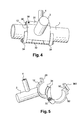
- the lower saddle 22 can be equipped with one or more tilting levers 34. As shown in FIGS. Figures 2a , 4 and 5 it can indeed provide two tilt levers, which will better distribute the load on the pipe, and also avoid a cantilever of all when the operator transmits his effort through the barrel.
- the operator can, depending on the case, proceed directly to the welding of the connection socket on the pipe, or take advantage of the temporary fixing to achieve a fixation more safe (for example by means of fasteners 38 passing through holes 40 provided for this purpose in the free edges of the two saddles, as shown on the Figures 2a and 2b ), before continuing installation of the service plug.
- the device is removably attached to the lower seat 22, it can be removed after welding of the socket, then reused.
- the device object of the invention therefore has the advantage of allowing the installation of a connection socket without the tools conventionally used, from the top of a dig well. Its manufacturing cost is low, and moreover, in its removable version, it is reusable.
- the implementation of the invention is simple and easy, for a reduced intervention time for the operator.
Landscapes
- Engineering & Computer Science (AREA)
- General Engineering & Computer Science (AREA)
- Mechanical Engineering (AREA)
- Branch Pipes, Bends, And The Like (AREA)
- Quick-Acting Or Multi-Walled Pipe Joints (AREA)
Applications Claiming Priority (1)
| Application Number | Priority Date | Filing Date | Title |
|---|---|---|---|
| FR0955441A FR2948745B1 (fr) | 2009-07-31 | 2009-07-31 | Ensemble pour prise de branchement d'une derivation sur une canalisation de transport de fluide |
Publications (2)
| Publication Number | Publication Date |
|---|---|
| EP2280210A1 true EP2280210A1 (de) | 2011-02-02 |
| EP2280210B1 EP2280210B1 (de) | 2015-07-29 |
Family
ID=41821233
Family Applications (1)
| Application Number | Title | Priority Date | Filing Date |
|---|---|---|---|
| EP10162030.0A Not-in-force EP2280210B1 (de) | 2009-07-31 | 2010-05-05 | Abzweigungsvorrichtung für eine Kanalisation zum Transport von Flüssigkeiten |
Country Status (4)
| Country | Link |
|---|---|
| EP (1) | EP2280210B1 (de) |
| CN (1) | CN101988608A (de) |
| ES (1) | ES2550802T3 (de) |
| FR (1) | FR2948745B1 (de) |
Cited By (2)
| Publication number | Priority date | Publication date | Assignee | Title |
|---|---|---|---|---|
| WO2016083786A1 (en) * | 2014-11-24 | 2016-06-02 | Thomas Dudley Limited | Boring device |
| FR3035701A1 (fr) * | 2015-04-30 | 2016-11-04 | South Offshore | Collier de montage |
Families Citing this family (4)
| Publication number | Priority date | Publication date | Assignee | Title |
|---|---|---|---|---|
| CN104696655A (zh) * | 2013-12-06 | 2015-06-10 | 瑞好聚合物(苏州)有限公司 | 管道鞍形座 |
| FR3024254B1 (fr) * | 2014-07-25 | 2018-08-03 | Suez Environnement | Procede de detection d'anomalies dans un reseau de distribution, en particulier distribution d'eau |
| CN110005520B (zh) * | 2019-03-25 | 2024-04-19 | 浙江创格科技股份有限公司 | 一种可调方向型发动机线束支架 |
| FR3140146B1 (fr) * | 2022-09-26 | 2025-02-21 | Avady Pool | Collier de prise en charge d’accessoire sur canalisation et ensemble formé d’un tel collier et d’une sonde de mesure |
Citations (5)
| Publication number | Priority date | Publication date | Assignee | Title |
|---|---|---|---|---|
| EP0536427A1 (de) * | 1991-07-10 | 1993-04-14 | agru Alois Gruber G.m.b.H. | Anbohrschelle für Fluidleitungen, insbesondere für Gas und Wasser |
| FR2768213A1 (fr) | 1997-09-10 | 1999-03-12 | Gaz De France | Procede et dispositif de mise en place d'une prise de branchement depuis le haut d'un puits de fouille |
| EP1331429A1 (de) * | 2002-01-12 | 2003-07-30 | agru Kunststofftechnik GmbH | Vorrichtung zum Anzapfen von Leitungen |
| FR2869089A1 (fr) | 2004-04-15 | 2005-10-21 | Gaz De France | Procede et dispositif pour poser une prise de branchement sur une canalisation |
| FR2924962A1 (fr) * | 2007-12-17 | 2009-06-19 | Gaz De France Sa | Dispositif de grattage d'un tube |
-
2009
- 2009-07-31 FR FR0955441A patent/FR2948745B1/fr not_active Expired - Fee Related
-
2010
- 2010-05-05 ES ES10162030.0T patent/ES2550802T3/es active Active
- 2010-05-05 EP EP10162030.0A patent/EP2280210B1/de not_active Not-in-force
- 2010-07-29 CN CN2010102448974A patent/CN101988608A/zh active Pending
Patent Citations (5)
| Publication number | Priority date | Publication date | Assignee | Title |
|---|---|---|---|---|
| EP0536427A1 (de) * | 1991-07-10 | 1993-04-14 | agru Alois Gruber G.m.b.H. | Anbohrschelle für Fluidleitungen, insbesondere für Gas und Wasser |
| FR2768213A1 (fr) | 1997-09-10 | 1999-03-12 | Gaz De France | Procede et dispositif de mise en place d'une prise de branchement depuis le haut d'un puits de fouille |
| EP1331429A1 (de) * | 2002-01-12 | 2003-07-30 | agru Kunststofftechnik GmbH | Vorrichtung zum Anzapfen von Leitungen |
| FR2869089A1 (fr) | 2004-04-15 | 2005-10-21 | Gaz De France | Procede et dispositif pour poser une prise de branchement sur une canalisation |
| FR2924962A1 (fr) * | 2007-12-17 | 2009-06-19 | Gaz De France Sa | Dispositif de grattage d'un tube |
Cited By (6)
| Publication number | Priority date | Publication date | Assignee | Title |
|---|---|---|---|---|
| WO2016083786A1 (en) * | 2014-11-24 | 2016-06-02 | Thomas Dudley Limited | Boring device |
| CN107110413A (zh) * | 2014-11-24 | 2017-08-29 | 托马斯达德利有限公司 | 钻孔装置 |
| US10018295B2 (en) | 2014-11-24 | 2018-07-10 | Thomas Dudley Limited | Boring device |
| CN107110413B (zh) * | 2014-11-24 | 2019-07-26 | 托马斯达德利有限公司 | 钻孔装置 |
| AU2020239737B2 (en) * | 2014-11-24 | 2021-11-04 | Thomas Dudley Limited | Boring device |
| FR3035701A1 (fr) * | 2015-04-30 | 2016-11-04 | South Offshore | Collier de montage |
Also Published As
| Publication number | Publication date |
|---|---|
| FR2948745B1 (fr) | 2011-10-07 |
| CN101988608A (zh) | 2011-03-23 |
| FR2948745A1 (fr) | 2011-02-04 |
| ES2550802T3 (es) | 2015-11-12 |
| EP2280210B1 (de) | 2015-07-29 |
Similar Documents
| Publication | Publication Date | Title |
|---|---|---|
| EP2280210B1 (de) | Abzweigungsvorrichtung für eine Kanalisation zum Transport von Flüssigkeiten | |
| EP0902229B1 (de) | Verfahren und Vorrichtung zum Positionieren eines unterirdischen Rohrabzweigungsstückes von der Oberfläche aus | |
| EP0661492B1 (de) | Vorrichtung zum Setzen eines Rohrabzweigstückes an eine Rohrleitung | |
| WO2007110514A1 (fr) | Support dit orbital comprenant au moins deux pieces en forme de segment de cercle raccordables l'une a l'autre; dispositif de soudage bout a bout de conduits pour former une canalisation de type pipeline comprenant un tel support orbital | |
| FR2544296A1 (fr) | Enrouleur portable pour tuyauterie souple, notamment pour vehicules automobiles, caravanes, autobus, bateaux, terrasses et petits jardins | |
| FR2643838A1 (fr) | Dispositif de fixation rigide pour des pieces suspendues telles que poincons de presse-plieuse | |
| FR2721013A1 (fr) | Appareil d'ouverture et de fermeture d'un couvercle de trou d'homme. | |
| FR2981722A1 (fr) | Dispositif support de positionnement pour cables le long de conduits de type pipeline immerges | |
| EP2384963B1 (de) | Unterwasserverbindungsstück zur Verbindung einer Erdölanlage, das mit einer Trennschutzvorrichtung ausgestattet ist | |
| EP1586801B1 (de) | Verfahren und Vorrichtung zum Setzen eines Rohrabzweigstückes an eine Rohrleitung | |
| EP1586802A1 (de) | Verfahren zum Verbinden eines Abzweigrohrs an eine Hauptleitung und ein unterirdisches Flüssigkeitsverteilungsnetz | |
| FR3016950A1 (fr) | Raccord pour circuit de transport de fluide et circuit de transport de fluide comprenant un tel raccord | |
| WO2012143474A1 (fr) | Système de connexion pour la fixation d'un dispositif de portage | |
| EP2548206B1 (de) | Verstopfungsvorrichtung zum verstopfen einer rohrleitung für eine flüssigkeit, beispielsweise zum einsatz in einer kernreaktoranlage, insbesondere in verbindung mit einer an der bodenseite eines dampferzeugers angebrachten abflussleitung | |
| FR2952625A1 (fr) | Outil de levage de plaques de voirie | |
| FR3044379A1 (fr) | Dispositif de maintien en position d'un tuyau a auto-serrage | |
| FR2939062A1 (fr) | Dispositif et procede pour redresser une conduite souple ayant une portion d'extremite recourbee, en vue de son raccordement | |
| FR2654798A1 (fr) | Outil pour la mise en place d'un embout a une extremite d'un tube. | |
| FR2982339A1 (fr) | Outil d'emboitement et de deboitement pour elements s'emboitant composant une tuyauterie | |
| EP1170200B1 (de) | Montierhilfe für Raupenkette | |
| FR2779206A1 (fr) | Dispositif de maintien d'une canalisation secondaire sur une prise de branchement et procede utilisant ce dispositif pour relier une canalisation secondaire a une canalisation principale | |
| EP0726417B1 (de) | Verbindungsvorrichtung zum Schnellverbinden von zwei Rohren | |
| BE1020845A5 (fr) | Regard de chaussee a cadre et tampon ameliores. | |
| EP2010720B1 (de) | Vorrichtung zur verbindung eines werkzeugs mit dem ausleger einer maschine, wie zum beispiel einem hydraulikbagger | |
| EP1541915B1 (de) | Vorrichtung zum Verbinden von Leitungselementen und entsprechendes Verbindungsverfahren |
Legal Events
| Date | Code | Title | Description |
|---|---|---|---|
| PUAI | Public reference made under article 153(3) epc to a published international application that has entered the european phase |
Free format text: ORIGINAL CODE: 0009012 |
|
| AK | Designated contracting states |
Kind code of ref document: A1 Designated state(s): AL AT BE BG CH CY CZ DE DK EE ES FI FR GB GR HR HU IE IS IT LI LT LU LV MC MK MT NL NO PL PT RO SE SI SK SM TR |
|
| AX | Request for extension of the european patent |
Extension state: BA ME RS |
|
| RAP1 | Party data changed (applicant data changed or rights of an application transferred) |
Owner name: GDF SUEZ |
|
| 17P | Request for examination filed |
Effective date: 20110802 |
|
| 17Q | First examination report despatched |
Effective date: 20120801 |
|
| GRAP | Despatch of communication of intention to grant a patent |
Free format text: ORIGINAL CODE: EPIDOSNIGR1 |
|
| INTG | Intention to grant announced |
Effective date: 20141104 |
|
| GRAS | Grant fee paid |
Free format text: ORIGINAL CODE: EPIDOSNIGR3 |
|
| GRAP | Despatch of communication of intention to grant a patent |
Free format text: ORIGINAL CODE: EPIDOSNIGR1 |
|
| INTG | Intention to grant announced |
Effective date: 20150413 |
|
| GRAA | (expected) grant |
Free format text: ORIGINAL CODE: 0009210 |
|
| AK | Designated contracting states |
Kind code of ref document: B1 Designated state(s): AL AT BE BG CH CY CZ DE DK EE ES FI FR GB GR HR HU IE IS IT LI LT LU LV MC MK MT NL NO PL PT RO SE SI SK SM TR |
|
| REG | Reference to a national code |
Ref country code: GB Ref legal event code: FG4D Free format text: NOT ENGLISH |
|
| REG | Reference to a national code |
Ref country code: CH Ref legal event code: EP |
|
| REG | Reference to a national code |
Ref country code: AT Ref legal event code: REF Ref document number: 739606 Country of ref document: AT Kind code of ref document: T Effective date: 20150815 |
|
| REG | Reference to a national code |
Ref country code: IE Ref legal event code: FG4D Free format text: LANGUAGE OF EP DOCUMENT: FRENCH |
|
| REG | Reference to a national code |
Ref country code: DE Ref legal event code: R096 Ref document number: 602010026164 Country of ref document: DE |
|
| REG | Reference to a national code |
Ref country code: ES Ref legal event code: FG2A Ref document number: 2550802 Country of ref document: ES Kind code of ref document: T3 Effective date: 20151112 |
|
| REG | Reference to a national code |
Ref country code: AT Ref legal event code: MK05 Ref document number: 739606 Country of ref document: AT Kind code of ref document: T Effective date: 20150729 |
|
| REG | Reference to a national code |
Ref country code: LT Ref legal event code: MG4D |
|
| REG | Reference to a national code |
Ref country code: NL Ref legal event code: MP Effective date: 20150729 |
|
| PG25 | Lapsed in a contracting state [announced via postgrant information from national office to epo] |
Ref country code: GR Free format text: LAPSE BECAUSE OF FAILURE TO SUBMIT A TRANSLATION OF THE DESCRIPTION OR TO PAY THE FEE WITHIN THE PRESCRIBED TIME-LIMIT Effective date: 20151030 Ref country code: NO Free format text: LAPSE BECAUSE OF FAILURE TO SUBMIT A TRANSLATION OF THE DESCRIPTION OR TO PAY THE FEE WITHIN THE PRESCRIBED TIME-LIMIT Effective date: 20151029 Ref country code: FI Free format text: LAPSE BECAUSE OF FAILURE TO SUBMIT A TRANSLATION OF THE DESCRIPTION OR TO PAY THE FEE WITHIN THE PRESCRIBED TIME-LIMIT Effective date: 20150729 Ref country code: LT Free format text: LAPSE BECAUSE OF FAILURE TO SUBMIT A TRANSLATION OF THE DESCRIPTION OR TO PAY THE FEE WITHIN THE PRESCRIBED TIME-LIMIT Effective date: 20150729 Ref country code: LV Free format text: LAPSE BECAUSE OF FAILURE TO SUBMIT A TRANSLATION OF THE DESCRIPTION OR TO PAY THE FEE WITHIN THE PRESCRIBED TIME-LIMIT Effective date: 20150729 |
|
| PG25 | Lapsed in a contracting state [announced via postgrant information from national office to epo] |
Ref country code: PL Free format text: LAPSE BECAUSE OF FAILURE TO SUBMIT A TRANSLATION OF THE DESCRIPTION OR TO PAY THE FEE WITHIN THE PRESCRIBED TIME-LIMIT Effective date: 20150729 Ref country code: HR Free format text: LAPSE BECAUSE OF FAILURE TO SUBMIT A TRANSLATION OF THE DESCRIPTION OR TO PAY THE FEE WITHIN THE PRESCRIBED TIME-LIMIT Effective date: 20150729 Ref country code: AT Free format text: LAPSE BECAUSE OF FAILURE TO SUBMIT A TRANSLATION OF THE DESCRIPTION OR TO PAY THE FEE WITHIN THE PRESCRIBED TIME-LIMIT Effective date: 20150729 Ref country code: PT Free format text: LAPSE BECAUSE OF FAILURE TO SUBMIT A TRANSLATION OF THE DESCRIPTION OR TO PAY THE FEE WITHIN THE PRESCRIBED TIME-LIMIT Effective date: 20151130 Ref country code: IS Free format text: LAPSE BECAUSE OF FAILURE TO SUBMIT A TRANSLATION OF THE DESCRIPTION OR TO PAY THE FEE WITHIN THE PRESCRIBED TIME-LIMIT Effective date: 20151129 Ref country code: SE Free format text: LAPSE BECAUSE OF FAILURE TO SUBMIT A TRANSLATION OF THE DESCRIPTION OR TO PAY THE FEE WITHIN THE PRESCRIBED TIME-LIMIT Effective date: 20150729 |
|
| PG25 | Lapsed in a contracting state [announced via postgrant information from national office to epo] |
Ref country code: NL Free format text: LAPSE BECAUSE OF FAILURE TO SUBMIT A TRANSLATION OF THE DESCRIPTION OR TO PAY THE FEE WITHIN THE PRESCRIBED TIME-LIMIT Effective date: 20150729 |
|
| REG | Reference to a national code |
Ref country code: FR Ref legal event code: PLFP Year of fee payment: 7 |
|
| PG25 | Lapsed in a contracting state [announced via postgrant information from national office to epo] |
Ref country code: SK Free format text: LAPSE BECAUSE OF FAILURE TO SUBMIT A TRANSLATION OF THE DESCRIPTION OR TO PAY THE FEE WITHIN THE PRESCRIBED TIME-LIMIT Effective date: 20150729 Ref country code: CZ Free format text: LAPSE BECAUSE OF FAILURE TO SUBMIT A TRANSLATION OF THE DESCRIPTION OR TO PAY THE FEE WITHIN THE PRESCRIBED TIME-LIMIT Effective date: 20150729 Ref country code: EE Free format text: LAPSE BECAUSE OF FAILURE TO SUBMIT A TRANSLATION OF THE DESCRIPTION OR TO PAY THE FEE WITHIN THE PRESCRIBED TIME-LIMIT Effective date: 20150729 Ref country code: DK Free format text: LAPSE BECAUSE OF FAILURE TO SUBMIT A TRANSLATION OF THE DESCRIPTION OR TO PAY THE FEE WITHIN THE PRESCRIBED TIME-LIMIT Effective date: 20150729 |
|
| REG | Reference to a national code |
Ref country code: DE Ref legal event code: R097 Ref document number: 602010026164 Country of ref document: DE |
|
| PG25 | Lapsed in a contracting state [announced via postgrant information from national office to epo] |
Ref country code: RO Free format text: LAPSE BECAUSE OF FAILURE TO SUBMIT A TRANSLATION OF THE DESCRIPTION OR TO PAY THE FEE WITHIN THE PRESCRIBED TIME-LIMIT Effective date: 20150729 |
|
| PLBE | No opposition filed within time limit |
Free format text: ORIGINAL CODE: 0009261 |
|
| STAA | Information on the status of an ep patent application or granted ep patent |
Free format text: STATUS: NO OPPOSITION FILED WITHIN TIME LIMIT |
|
| 26N | No opposition filed |
Effective date: 20160502 |
|
| PG25 | Lapsed in a contracting state [announced via postgrant information from national office to epo] |
Ref country code: SI Free format text: LAPSE BECAUSE OF FAILURE TO SUBMIT A TRANSLATION OF THE DESCRIPTION OR TO PAY THE FEE WITHIN THE PRESCRIBED TIME-LIMIT Effective date: 20150729 Ref country code: BE Free format text: LAPSE BECAUSE OF NON-PAYMENT OF DUE FEES Effective date: 20160531 |
|
| PG25 | Lapsed in a contracting state [announced via postgrant information from national office to epo] |
Ref country code: LU Free format text: LAPSE BECAUSE OF FAILURE TO SUBMIT A TRANSLATION OF THE DESCRIPTION OR TO PAY THE FEE WITHIN THE PRESCRIBED TIME-LIMIT Effective date: 20160505 |
|
| REG | Reference to a national code |
Ref country code: CH Ref legal event code: PL |
|
| PG25 | Lapsed in a contracting state [announced via postgrant information from national office to epo] |
Ref country code: LI Free format text: LAPSE BECAUSE OF NON-PAYMENT OF DUE FEES Effective date: 20160531 Ref country code: CH Free format text: LAPSE BECAUSE OF NON-PAYMENT OF DUE FEES Effective date: 20160531 |
|
| REG | Reference to a national code |
Ref country code: IE Ref legal event code: MM4A |
|
| REG | Reference to a national code |
Ref country code: FR Ref legal event code: PLFP Year of fee payment: 8 |
|
| PG25 | Lapsed in a contracting state [announced via postgrant information from national office to epo] |
Ref country code: IE Free format text: LAPSE BECAUSE OF NON-PAYMENT OF DUE FEES Effective date: 20160505 |
|
| REG | Reference to a national code |
Ref country code: FR Ref legal event code: PLFP Year of fee payment: 9 |
|
| PG25 | Lapsed in a contracting state [announced via postgrant information from national office to epo] |
Ref country code: HU Free format text: LAPSE BECAUSE OF FAILURE TO SUBMIT A TRANSLATION OF THE DESCRIPTION OR TO PAY THE FEE WITHIN THE PRESCRIBED TIME-LIMIT; INVALID AB INITIO Effective date: 20100505 Ref country code: CY Free format text: LAPSE BECAUSE OF FAILURE TO SUBMIT A TRANSLATION OF THE DESCRIPTION OR TO PAY THE FEE WITHIN THE PRESCRIBED TIME-LIMIT Effective date: 20150729 Ref country code: SM Free format text: LAPSE BECAUSE OF FAILURE TO SUBMIT A TRANSLATION OF THE DESCRIPTION OR TO PAY THE FEE WITHIN THE PRESCRIBED TIME-LIMIT Effective date: 20150729 |
|
| PG25 | Lapsed in a contracting state [announced via postgrant information from national office to epo] |
Ref country code: TR Free format text: LAPSE BECAUSE OF FAILURE TO SUBMIT A TRANSLATION OF THE DESCRIPTION OR TO PAY THE FEE WITHIN THE PRESCRIBED TIME-LIMIT Effective date: 20150729 Ref country code: MT Free format text: LAPSE BECAUSE OF FAILURE TO SUBMIT A TRANSLATION OF THE DESCRIPTION OR TO PAY THE FEE WITHIN THE PRESCRIBED TIME-LIMIT Effective date: 20150729 Ref country code: MK Free format text: LAPSE BECAUSE OF FAILURE TO SUBMIT A TRANSLATION OF THE DESCRIPTION OR TO PAY THE FEE WITHIN THE PRESCRIBED TIME-LIMIT Effective date: 20150729 Ref country code: MC Free format text: LAPSE BECAUSE OF FAILURE TO SUBMIT A TRANSLATION OF THE DESCRIPTION OR TO PAY THE FEE WITHIN THE PRESCRIBED TIME-LIMIT Effective date: 20150729 |
|
| PG25 | Lapsed in a contracting state [announced via postgrant information from national office to epo] |
Ref country code: BG Free format text: LAPSE BECAUSE OF FAILURE TO SUBMIT A TRANSLATION OF THE DESCRIPTION OR TO PAY THE FEE WITHIN THE PRESCRIBED TIME-LIMIT Effective date: 20150729 |
|
| PG25 | Lapsed in a contracting state [announced via postgrant information from national office to epo] |
Ref country code: AL Free format text: LAPSE BECAUSE OF FAILURE TO SUBMIT A TRANSLATION OF THE DESCRIPTION OR TO PAY THE FEE WITHIN THE PRESCRIBED TIME-LIMIT Effective date: 20150729 |
|
| REG | Reference to a national code |
Ref country code: GB Ref legal event code: 732E Free format text: REGISTERED BETWEEN 20190131 AND 20190206 |
|
| REG | Reference to a national code |
Ref country code: ES Ref legal event code: PC2A Owner name: GRTGAZ Effective date: 20190823 |
|
| PGFP | Annual fee paid to national office [announced via postgrant information from national office to epo] |
Ref country code: DE Payment date: 20210421 Year of fee payment: 12 Ref country code: IT Payment date: 20210422 Year of fee payment: 12 |
|
| PGFP | Annual fee paid to national office [announced via postgrant information from national office to epo] |
Ref country code: ES Payment date: 20210601 Year of fee payment: 12 Ref country code: GB Payment date: 20210422 Year of fee payment: 12 |
|
| REG | Reference to a national code |
Ref country code: DE Ref legal event code: R081 Ref document number: 602010026164 Country of ref document: DE Owner name: GRTGAZ S.A., FR Free format text: FORMER OWNER: GDF SUEZ, COURBEVOIE, FR |
|
| REG | Reference to a national code |
Ref country code: DE Ref legal event code: R119 Ref document number: 602010026164 Country of ref document: DE |
|
| GBPC | Gb: european patent ceased through non-payment of renewal fee |
Effective date: 20220505 |
|
| PG25 | Lapsed in a contracting state [announced via postgrant information from national office to epo] |
Ref country code: GB Free format text: LAPSE BECAUSE OF NON-PAYMENT OF DUE FEES Effective date: 20220505 Ref country code: DE Free format text: LAPSE BECAUSE OF NON-PAYMENT OF DUE FEES Effective date: 20221201 |
|
| REG | Reference to a national code |
Ref country code: ES Ref legal event code: FD2A Effective date: 20230703 |
|
| PG25 | Lapsed in a contracting state [announced via postgrant information from national office to epo] |
Ref country code: IT Free format text: LAPSE BECAUSE OF NON-PAYMENT OF DUE FEES Effective date: 20220505 Ref country code: ES Free format text: LAPSE BECAUSE OF NON-PAYMENT OF DUE FEES Effective date: 20220506 |
|
| PGFP | Annual fee paid to national office [announced via postgrant information from national office to epo] |
Ref country code: FR Payment date: 20240530 Year of fee payment: 15 |
|
| PG25 | Lapsed in a contracting state [announced via postgrant information from national office to epo] |
Ref country code: FR Free format text: LAPSE BECAUSE OF NON-PAYMENT OF DUE FEES Effective date: 20250531 |