EP2280225A2 - Effusionskühlung für doppelwandige Gasturbinenbrennkammern - Google Patents
Effusionskühlung für doppelwandige Gasturbinenbrennkammern Download PDFInfo
- Publication number
- EP2280225A2 EP2280225A2 EP10170528A EP10170528A EP2280225A2 EP 2280225 A2 EP2280225 A2 EP 2280225A2 EP 10170528 A EP10170528 A EP 10170528A EP 10170528 A EP10170528 A EP 10170528A EP 2280225 A2 EP2280225 A2 EP 2280225A2
- Authority
- EP
- European Patent Office
- Prior art keywords
- effusion cooling
- cooling holes
- row
- disposed
- gas turbine
- Prior art date
- Legal status (The legal status is an assumption and is not a legal conclusion. Google has not performed a legal analysis and makes no representation as to the accuracy of the status listed.)
- Granted
Links
Images


Classifications
-
- F—MECHANICAL ENGINEERING; LIGHTING; HEATING; WEAPONS; BLASTING
- F23—COMBUSTION APPARATUS; COMBUSTION PROCESSES
- F23R—GENERATING COMBUSTION PRODUCTS OF HIGH PRESSURE OR HIGH VELOCITY, e.g. GAS-TURBINE COMBUSTION CHAMBERS
- F23R3/00—Continuous combustion chambers using liquid or gaseous fuel
- F23R3/02—Continuous combustion chambers using liquid or gaseous fuel characterised by the air-flow or gas-flow configuration
- F23R3/04—Air inlet arrangements
- F23R3/06—Arrangement of apertures along the flame tube
-
- F—MECHANICAL ENGINEERING; LIGHTING; HEATING; WEAPONS; BLASTING
- F23—COMBUSTION APPARATUS; COMBUSTION PROCESSES
- F23R—GENERATING COMBUSTION PRODUCTS OF HIGH PRESSURE OR HIGH VELOCITY, e.g. GAS-TURBINE COMBUSTION CHAMBERS
- F23R3/00—Continuous combustion chambers using liquid or gaseous fuel
- F23R3/005—Combined with pressure or heat exchangers
-
- F—MECHANICAL ENGINEERING; LIGHTING; HEATING; WEAPONS; BLASTING
- F23—COMBUSTION APPARATUS; COMBUSTION PROCESSES
- F23R—GENERATING COMBUSTION PRODUCTS OF HIGH PRESSURE OR HIGH VELOCITY, e.g. GAS-TURBINE COMBUSTION CHAMBERS
- F23R2900/00—Special features of, or arrangements for continuous combustion chambers; Combustion processes therefor
- F23R2900/03041—Effusion cooled combustion chamber walls or domes
-
- F—MECHANICAL ENGINEERING; LIGHTING; HEATING; WEAPONS; BLASTING
- F23—COMBUSTION APPARATUS; COMBUSTION PROCESSES
- F23R—GENERATING COMBUSTION PRODUCTS OF HIGH PRESSURE OR HIGH VELOCITY, e.g. GAS-TURBINE COMBUSTION CHAMBERS
- F23R2900/00—Special features of, or arrangements for continuous combustion chambers; Combustion processes therefor
- F23R2900/03044—Impingement cooled combustion chamber walls or subassemblies
-
- Y—GENERAL TAGGING OF NEW TECHNOLOGICAL DEVELOPMENTS; GENERAL TAGGING OF CROSS-SECTIONAL TECHNOLOGIES SPANNING OVER SEVERAL SECTIONS OF THE IPC; TECHNICAL SUBJECTS COVERED BY FORMER USPC CROSS-REFERENCE ART COLLECTIONS [XRACs] AND DIGESTS
- Y02—TECHNOLOGIES OR APPLICATIONS FOR MITIGATION OR ADAPTATION AGAINST CLIMATE CHANGE
- Y02T—CLIMATE CHANGE MITIGATION TECHNOLOGIES RELATED TO TRANSPORTATION
- Y02T50/00—Aeronautics or air transport
- Y02T50/60—Efficient propulsion technologies, e.g. for aircraft
Definitions
- the present invention relates to gas turbine engines, and more particularly, to dual wall, gas turbine engine combustors.
- a gas turbine engine may be used to power various types of vehicles and systems.
- a particular type of gas turbine engine that may be used to power aircraft is a turbofan gas turbine engine.
- a turbofan gas turbine engine conventionally includes, for example, five major sections: a fan section, a compressor section, a combustor section, a turbine section, and an exhaust section.
- the fan section is typically positioned at the inlet section of the engine and includes a fan that induces air from the surrounding environment into the engine and accelerates a portion of this air toward the compressor section. The remaining portion of air induced into the fan section is accelerated into and through a bypass plenum and out the exhaust section.
- the compressor section raises the pressure of the air received from the fan section.
- the compressed air from the compressor section then enters a combustion chamber of the combustor section, where a ring of fuel nozzles injects a steady stream of fuel.
- the fuel and air mixture is ignited to form combustion gases from which energy is extracted in the turbine section.
- Known combustors include inner and outer liners that define the annular combustion chamber.
- the combustors in gas turbine engines typically operate at relatively high temperatures, including temperatures over 3500° F. Such high temperatures can adversely impact the service life of a combustor.
- some form of cooling is typically provided for the combustor.
- One example of combustor cooling is known as effusion cooling.
- Effusion cooling involves a matrix of relatively small diameter effusion cooling holes extending through the combustor liners to admit a flow of cooling air.
- the effusion cooling holes are typically angled relative to a surface of the combustor to generate a cooling film on the inner wall of the liners. This angle also increases the length of the effusion holes through the liners, which increases the surface area from which the cooling flow removes heat from the liner.
- effusion cooling is generally effective, it does suffer certain drawbacks.
- one characteristic of effusion cooling is that the film effectiveness may be relatively low at or near upstream sections of the combustor liner.
- the cooling film once it is sufficiently established, may be interrupted by one or more rows of major combustor orifices, such as dilution holes.
- some form of cooling augmentation may be used in the upstream sections of effusion cooled combustor liners and/or at locations downstream of major combustor orifices. Such cooling augmentation can complicate the construction of combustor and increase overall size, weight, and/or costs.
- a gas turbine engine combustor has an upstream end and a downstream end and extends in an axial direction between the upstream and downstream ends.
- a dual wall outer liner has a hot wall, a cold wall at least partially surrounding the hot wall, an upstream end, and a downstream end. The outer liner extends in the axial direction between the upstream and downstream ends. The outer liner is spaced apart from, and at least partially surrounding, the inner liner.
- a dome assembly is coupled between the upstream ends of the inner and outer liners to define a combustion chamber between the inner liner and the hot wall of the outer liner.
- a plurality of rows of effusion cooling holes are disposed in the hot wall, including a first row of effusion cooling holes disposed at a tangential angle of between about 70° and about 90° relative to the axial direction and a second row of effusion cooling holes disposed at a tangential angle of between about 0° and about 20° relative to the axial direction.
- a combustor liner segment includes a hot side; a cold side opposing the hot side and having an upstream end and a downstream end, the cold side extending in an axial direction between the upstream and downstream ends; and a plurality of effusion cooling holes extending from the cold side to the hot side, including a first row of effusion cooling holes disposed at a tangential angle of between about 70° and about 90° relative to the axial direction and a second row of effusion cooling holes disposed at a tangential angle of between about 0° and about 20° relative to the axial direction.
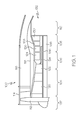
- FIG. 1 is a simplified cross-sectional side view of an exemplary multi-spool turbofan gas turbine jet engine according to an exemplary embodiment
- FIG. 2 is a cross-sectional view of an exemplary combustor that may be used in the engine of FIG. 1 ;
- FIG. 3 is a plan view of a portion of a combustor liner according to an exemplary embodiment that may be used in the combustor shown in FIG. 2 ;
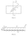
- FIG. 4 is a close-up view of the exemplary combustor liner shown in FIG. 3 , depicting the configuration of an exemplary effusion cooling hole that extends therethrough;
- FIG. 5 is a cross section view of a portion of the exemplary combustor liner shown in FIG. 3 ;
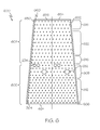
- FIG. 6 is a plan view of a combustor liner section that may be used in the combustor shown in FIG. 2 in accordance with an alternate exemplary embodiment.
- exemplary embodiments disclosed herein provide dual wall combustors with liners having hot and cold walls.
- the hot wall may include an upstream row of effusion cooling holes disposed in a tangential direction and a downstream row of effusion cooling holes disposed in an axial direction. Downstream of dilution openings, the hot wall may have another row with effusion cooling holes disposed in the tangential direction.
- the combustor may further have impingement cooling holes in the cold wall of the dual wall liner.
- FIG. 1 An exemplary embodiment of a multi-spool turbofan gas turbine jet engine 100 is depicted in FIG. 1 , and includes an intake section 102, a compressor section 104, a combustion section 106, a turbine section 108, and an exhaust section 110.
- the intake section 102 includes a fan 112, which is mounted in a fan case 114.
- the fan 112 draws in and accelerates air into the intake section 102.
- a fraction of the accelerated air exhausted from the fan 112 is directed through a bypass section 116 disposed between the fan case 114 and an engine cowl 118.
- the remaining fraction of air exhausted from the fan 112 is directed into the compressor section 104.
- the compressor section 104 includes an intermediate pressure compressor 120 and a high pressure compressor 122.
- the intermediate pressure compressor 120 raises the pressure of the air from the fan 112 and directs the compressed air into the high pressure compressor 122.
- the high pressure compressor 122 compresses the air further and directs the high pressure air into the combustion section 106.
- the combustion section 106 the high pressure air is mixed with fuel and combusted in a combustor 124. The combusted air is then directed into the turbine section 108.
- the turbine section 108 may have three turbines disposed in axial flow series, including a high pressure turbine 126, an intermediate pressure turbine 128, and a low pressure turbine 130.
- the combusted air from the combustion section 106 expands through each turbine, causing it to rotate.
- the air is then exhausted through a propulsion nozzle 132 disposed in the exhaust section 110.
- each drives equipment in the engine 100 via concentrically disposed shafts or spools.
- the high pressure turbine 126 drives the high pressure compressor 122 via a high pressure spool 134
- the intermediate pressure turbine 128 drives the intermediate pressure compressor 120 via an intermediate pressure spool 136
- the low pressure turbine 130 drives the fan 112 via a low pressure spool 138.
- the air is then exhausted through a propulsion nozzle 132 disposed in the exhaust section 110.
- the combustor 124 which in the depicted embodiment is implemented as an annular combustor, includes an inner liner 202, an outer liner 204, and a dome 206.
- the inner liner 202 is a dual wall liner with a hot wall 208 and a cold wall 210 with upstream and downstream ends 212, 214.
- the outer liner 204 which at least partially surrounds the inner liner 202, is also a dual wall liner that includes a hot wall 216 and a cold wall 218 with upstream and downstream ends 220, 222.
- the dome 206 is coupled between the upstream ends 212, 220 of the inner and outer liners 202, 204 to form a combustion chamber 228 therebetween.
- the downstream ends 214, 222 of the inner and outer liners 202, 204 form an opening 230 through which combusted air flows into the turbine section 108 ( FIG. 1 ).
- the inner and outer liners 202, 204 may each include at least one circumferential row of dilution openings 232, 234.
- the dilution openings 232, 234 generally admit additional air into the combustion chamber 228 to establish combustor aerodynamics and cool the exhaust gases to acceptable levels before entering the turbine section 108 ( FIG. 1 ).
- two rows of dilution openings 232, 234 are provided, including primary dilution openings 232 and secondary dilution openings 234.
- the dome 206 also includes a number of circumferentially spaced, axially facing swirler assembly openings 236.
- Each of the swirler assembly openings 236 is configured to have mounted therein a swirler assembly 250.
- the swirler assemblies mix fuel and air, and the fuel/air mixture is then discharged into the combustion chamber 228 where it is ignited by one or more igniters (not shown).
- the inner and outer liners 202, 204 include a plurality of impingement cooling holes and a plurality of effusion cooling holes.
- the impingement cooling holes are arranged in the cold walls 210, 218 of the inner and outer liner 202, 204, and the effusion cooling holes are arranged in the hot walls 208, 216 of the inner and outer liners 202, 204.
- the impingement cooling holes allow cooling air to flow through the cold walls 210, 218 to the hot walls 208, 216.
- the effusion cooling holes enable air flow to cool the hot walls 208, 216 via convective heat transfer and by generating a cooling film on the inner surfaces of the inner and outer liners 202, 204.
- FIG. 3 is a plan view of a portion the outer liner 204.
- the plan view of FIG. 3 shows the hot wall 216 of the outer liner 204 between the upstream and downstream ends 224, 226.
- the hot wall 216 of the outer liner 204 includes a number of effusion cooling holes 304 that may be considered to be arranged in upstream and downstream sets 300, 302. It will be appreciated that the number of effusion cooling hole sets 300, 302 may vary, and may be selected to meet needed or desired cooling requirements.
- the upstream effusion cooling hole set 300 is disposed upstream of, or circumferentially aligned with, major combustor orifices, such as the dilution openings 232, 234, and the downstream effusion cooling hole set 302 is disposed downstream of, or circumferentially aligned with, the major combustor orifices.
- the upstream effusion cooling hole set 300 is upstream of and at least partially aligned with the dilution openings 232, 234 and the downstream effusion cooling hole set 302 is downstream of the dilution openings 232, 234.
- outer liner 204 could be implemented with more than two effusion cooling hole sets 300, 302 if needed or desired.
- the inner liner 202 is typically configured to include similarly arranged effusion cooling holes sets.
- Each effusion cooling hole set 300, 302 includes a number of effusion cooling holes 304 that extend through the hot wall 216 of the outer liner 204.
- the effusion cooling holes 304 in each effusion cooling hole set 300, 302 typically have a diameter of between about 0.01 inches and about 0.03 inches and are configured in a number of rows.
- each effusion cooling hole set 300, 302 includes one or more initial rows 306, 316 of effusion cooling holes 304, one or more final rows 308, 318 of effusion cooling holes 304 disposed downstream of the one or more initial rows 306, 316, and a number of interposed rows 312, 322 of effusion cooling holes 304 disposed between the initial rows 306, 316 and final rows 308, 318.
- the initial rows 306, 316 are disposed at the upstream-most extent of each effusion cooling hole set 300, 302, and the final rows 308, 318 are concomitantly disposed at the downstream-most extent of each effusion cooling hole set 300, 302.
- the total number of rows 306, 316, 308, 318, 312, 322 in an effusion cooling hole set 300, 302 may vary, and the number of initial rows 306, 316, final rows 308, 318, and interposed rows 312, 322 within an effusion cooling hole set 300, 302 may vary.
- each hole 304 is disposed at a tangential angle ( ⁇ T ) relative to an axial line 314 that extends between the outer liner upstream and downstream ends 224, 226. More specifically, and as shown more clearly in FIG. 4 , each effusion cooling hole 304 is disposed such that a centerline 402 thereof forms an angle ( ⁇ T ) relative to the axial line 314.
- each effusion cooling hole 304 in an initial row 306, 316 is typically disposed at a tangential angle ( ⁇ T ) of between about 70° and about 90°, particularly at about 90°, and each effusion cooling hole 304 in a final row 308, 318 is typically disposed at a tangential angle ( ⁇ T ) of between about 0° and about 20°, particularly at about 0°.
- the effusion cooling holes 304 in each of the interposed rows 312, 322 are typically disposed at a tangential angle ( ⁇ T ) that is less than the tangential angle ( ⁇ T ) of the effusion cooling holes 304 in each initial row 306, 316 and greater than the tangential angle ( ⁇ T ) of the effusion cooling holes 304 in each final row 308, 318.
- the tangential angle ( ⁇ T ) of the effusion cooling holes 304 in each of the interposed rows 312, 322 has a multiplicity of values that vary in a graduated manner as the rows 312, 322 progress downstream.
- each effusion cooling hole 304 is also preferably disposed at an inward angle ( ⁇ I ). More specifically, and as shown more clearly in FIG. 5 , each effusion cooling hole 304 extends through the liners 202, 204 at an acute angle relative to the liner outer surface. Although the inward angle ( ⁇ I ) may vary, in a particular exemplary embodiment, the inward angle ( ⁇ I ) is between about 10° and about 30°. As noted above, the outer liner 204 is a dual wall liner, and particularly is a dual wall liner with impingement-effusion cooling.
- the cold wall 218 includes a number of impingement cooling holes 510 that admit impingement jets 512 of cooling air to the hot wall 216.
- the impingement cooling holes 510 are typically 90° to the surface of the cold wall 218, although other arrangements are possible.
- the effusion cooling holes 304 of the hot wall 216 are relatively small, closely spaced holes serving to direct a flow of cooling air through the hot wall 216 such that a film of cooling air forms on the hot wall 216, as discussed in greater detail below.
- the inner liner 202 is similarly configured to be cooled with impingement-effusion cooling.
- the substantially transversely disposed effusion cooling holes 304 in each of the initial rows 306, 316 serve to establish a cooling film on the liner inner surfaces.
- the transition of the effusion cooling holes 304 from the substantially transverse tangential angle ( ⁇ T ) to the substantially axial tangential angle ( ⁇ T ) encourages cooling air flow in the downstream direction, which provides continued effective cooling of the liner inner surfaces while mitigating the swirl component of the upstream effusion cooling holes 304.
- FIG. 6 is a plan view of a combustor liner section 600 that may be used in the combustor shown in FIG. 2 in accordance with an alternate exemplary embodiment.
- the combustor 124 may have liners that are sectioned.
- the hot wall of the inner and/or outer liner may be constructed of a plurality of adjacent liner sections.
- One such liner section (or heat shield) 600 is shown in FIG. 6 .
- Each liner section 600 may include radially raised rails or edges 650, 652 that extend between an upstream end 624 and a downstream end 626.
- a raised rail or edge 654 may also be provided at the downstream end 626.
- the liner section 600 has effusion cooling holes 304 that are generally the same configuration as the view in FIG. 3 .
- the liner section 600 has effusion cooling holes 304 arranged in first and second effusion cooling hole sets 600, 602 corresponding to the effusion cooling hole sets 300, 302, including an initial row 606, 616 with effusion cooling holes 304 typically disposed at a tangential angle ( ⁇ T ) of between about 70° and about 90°, a final row 608, 618 is typically disposed at a tangential angle ( ⁇ T ) of between about 0° and about 20°, and interposed rows 612, 622 are typically disposed at a tangential angle ( ⁇ T ) that is less than the tangential angle ( ⁇ T ) of the initial row 606, 616 and greater than the tangential angle ( ⁇ T ) of each final row 608, 618.
- An additional row 660 of effusion cooling holes 304 may be arranged in an axial direction.
- the additional row 660 of effusion cooling holes 304 provides cooling air flow to the rail 650.
- another additional row 660 may be arranged adjacent to the rail 652.
- the effusion cooling holes 304 of the additional row 660 are disposed at a tangential angle of between about 70° and about 90°.
- the effusion cooling holes 304 of the additional row 660 are disposed at 90° relative to an axial direction, i.e., parallel to rail 650, although other angles are possible.
- a dual wall combustor has more challenging cooling requirements.
- the respective walls and other components may move relative to one another during operation, and as a result, different parts of the combustor may experience different amounts of thermal growth, stress and strain.
- the impingement-effusion cooling configuration described herein sufficiently cool the combustion chamber to accommodate, prevent or decrease thermal growth, stress and strain. In some embodiments, this is accomplished without additional cooling augmentation.
Landscapes
- Engineering & Computer Science (AREA)
- Chemical & Material Sciences (AREA)
- Combustion & Propulsion (AREA)
- Mechanical Engineering (AREA)
- General Engineering & Computer Science (AREA)
- Turbine Rotor Nozzle Sealing (AREA)
Applications Claiming Priority (1)
| Application Number | Priority Date | Filing Date | Title |
|---|---|---|---|
| US12/512,816 US9897320B2 (en) | 2009-07-30 | 2009-07-30 | Effusion cooled dual wall gas turbine combustors |
Publications (3)
| Publication Number | Publication Date |
|---|---|
| EP2280225A2 true EP2280225A2 (de) | 2011-02-02 |
| EP2280225A3 EP2280225A3 (de) | 2017-11-15 |
| EP2280225B1 EP2280225B1 (de) | 2019-07-10 |
Family
ID=43033214
Family Applications (1)
| Application Number | Title | Priority Date | Filing Date |
|---|---|---|---|
| EP10170528.3A Active EP2280225B1 (de) | 2009-07-30 | 2010-07-22 | Gasturbinenbrennkammer mit Effusionskühlung |
Country Status (2)
| Country | Link |
|---|---|
| US (1) | US9897320B2 (de) |
| EP (1) | EP2280225B1 (de) |
Cited By (4)
| Publication number | Priority date | Publication date | Assignee | Title |
|---|---|---|---|---|
| CN104197373A (zh) * | 2014-08-26 | 2014-12-10 | 南京航空航天大学 | 一种采用变截面台阶形多斜孔冷却结构的航空发动机燃烧室 |
| EP3077726A4 (de) * | 2013-12-06 | 2017-04-12 | United Technologies Corporation | Kühlung eines brennkammerhitzeschilds in der nähe einer löschöffnung |
| CN107257904A (zh) * | 2015-02-25 | 2017-10-17 | 赛峰直升机发动机公司 | 涡轮发动机的包括具有开口的贯通部件的燃烧室 |
| EP3851744A1 (de) * | 2020-01-17 | 2021-07-21 | Raytheon Technologies Corporation | Konvektionskühlung im bereich niedriger effusionsdichte einer brennkammerplatte |
Families Citing this family (26)
| Publication number | Priority date | Publication date | Assignee | Title |
|---|---|---|---|---|
| US8739546B2 (en) * | 2009-08-31 | 2014-06-03 | United Technologies Corporation | Gas turbine combustor with quench wake control |
| FR2979416B1 (fr) * | 2011-08-26 | 2013-09-20 | Turbomeca | Paroi de chambre de combustion |
| FR2982008B1 (fr) | 2011-10-26 | 2013-12-13 | Snecma | Paroi annulaire de chambre de combustion a refroidissement ameliore au niveau des trous primaires et de dilution |
| EP2644995A1 (de) * | 2012-03-27 | 2013-10-02 | Siemens Aktiengesellschaft | Verbesserte Lochanordnung von Auskleidungen einer Brennkammer eines Gasturbinenmotors mit niedriger Verbrennungsdynamik und niedrigen Emissionen |
| US9052111B2 (en) | 2012-06-22 | 2015-06-09 | United Technologies Corporation | Turbine engine combustor wall with non-uniform distribution of effusion apertures |
| US20140190171A1 (en) * | 2013-01-10 | 2014-07-10 | Honeywell International Inc. | Combustors with hybrid walled liners |
| CA2904200A1 (en) | 2013-03-05 | 2014-09-12 | Rolls-Royce Corporation | Dual-wall impingement, convection, effusion combustor tile |
| US9518739B2 (en) * | 2013-03-08 | 2016-12-13 | Pratt & Whitney Canada Corp. | Combustor heat shield with carbon avoidance feature |
| EP2971973B1 (de) * | 2013-03-14 | 2018-02-21 | United Technologies Corporation | Brennkammerplatte und brennkammer mit hitzeschild mit erhöhter beständigkeit |
| US10808928B2 (en) * | 2013-09-12 | 2020-10-20 | Raytheon Technologies Corporation | Boss for combustor panel |
| EP3066391B1 (de) * | 2013-11-05 | 2019-01-16 | United Technologies Corporation | Gekühlte brennkammerschwebewandplatte |
| EP3967854B1 (de) * | 2013-11-25 | 2023-07-05 | Raytheon Technologies Corporation | Anordnung für ein turbinentriebwerk |
| US10317080B2 (en) * | 2013-12-06 | 2019-06-11 | United Technologies Corporation | Co-swirl orientation of combustor effusion passages for gas turbine engine combustor |
| US10935241B2 (en) * | 2014-05-09 | 2021-03-02 | Raytheon Technologies Corporation | Additively manufactured hotspot portion of a turbine engine component having heat resistant properties and method of manufacture |
| WO2016099662A2 (en) * | 2014-10-31 | 2016-06-23 | General Electric Company | Engine component assembly |
| US20160258623A1 (en) * | 2015-03-05 | 2016-09-08 | United Technologies Corporation | Combustor and heat shield configurations for a gas turbine engine |
| EP3109550B1 (de) | 2015-06-19 | 2019-09-04 | Rolls-Royce Corporation | Turbinengekühlte kühlluft strömend durch eine rohranordnung |
| CA2933884A1 (en) * | 2015-06-30 | 2016-12-30 | Rolls-Royce Corporation | Combustor tile |
| GB201518345D0 (en) * | 2015-10-16 | 2015-12-02 | Rolls Royce | Combustor for a gas turbine engine |
| US10041677B2 (en) | 2015-12-17 | 2018-08-07 | General Electric Company | Combustion liner for use in a combustor assembly and method of manufacturing |
| US10816202B2 (en) | 2017-11-28 | 2020-10-27 | General Electric Company | Combustor liner for a gas turbine engine and an associated method thereof |
| JP6452877B1 (ja) * | 2018-04-10 | 2019-01-16 | 隆 長谷川 | 高揚力装置、飛行機の主翼、水中翼船の水中翼、及び飛行機のエンジンカウル |
| US11255543B2 (en) | 2018-08-07 | 2022-02-22 | General Electric Company | Dilution structure for gas turbine engine combustor |
| US11306919B2 (en) | 2018-10-19 | 2022-04-19 | Raytheon Technologies Corporation | Combustor panel cooling hole arrangement |
| US10775044B2 (en) | 2018-10-26 | 2020-09-15 | Honeywell International Inc. | Gas turbine engine dual-wall hot section structure |
| US11181269B2 (en) | 2018-11-15 | 2021-11-23 | General Electric Company | Involute trapped vortex combustor assembly |
Family Cites Families (19)
| Publication number | Priority date | Publication date | Assignee | Title |
|---|---|---|---|---|
| GB2044912B (en) * | 1979-03-22 | 1983-02-23 | Rolls Royce | Gas turbine combustion chamber |
| GB2221979B (en) * | 1988-08-17 | 1992-03-25 | Rolls Royce Plc | A combustion chamber for a gas turbine engine |
| GB9018014D0 (en) * | 1990-08-16 | 1990-10-03 | Rolls Royce Plc | Gas turbine engine combustor |
| DE19502328A1 (de) * | 1995-01-26 | 1996-08-01 | Bmw Rolls Royce Gmbh | Hitzeschild für eine Gasturbinen-Brennkammer |
| US6408629B1 (en) * | 2000-10-03 | 2002-06-25 | General Electric Company | Combustor liner having preferentially angled cooling holes |
| GB2373319B (en) * | 2001-03-12 | 2005-03-30 | Rolls Royce Plc | Combustion apparatus |
| US6513331B1 (en) | 2001-08-21 | 2003-02-04 | General Electric Company | Preferential multihole combustor liner |
| US7093439B2 (en) * | 2002-05-16 | 2006-08-22 | United Technologies Corporation | Heat shield panels for use in a combustor for a gas turbine engine |
| US20060037323A1 (en) * | 2004-08-20 | 2006-02-23 | Honeywell International Inc., | Film effectiveness enhancement using tangential effusion |
| US7506512B2 (en) * | 2005-06-07 | 2009-03-24 | Honeywell International Inc. | Advanced effusion cooling schemes for combustor domes |
| US7509809B2 (en) * | 2005-06-10 | 2009-03-31 | Pratt & Whitney Canada Corp. | Gas turbine engine combustor with improved cooling |
| US7631502B2 (en) * | 2005-12-14 | 2009-12-15 | United Technologies Corporation | Local cooling hole pattern |
| US7665307B2 (en) * | 2005-12-22 | 2010-02-23 | United Technologies Corporation | Dual wall combustor liner |
| US7546737B2 (en) * | 2006-01-24 | 2009-06-16 | Honeywell International Inc. | Segmented effusion cooled gas turbine engine combustor |
| FR2899315B1 (fr) * | 2006-03-30 | 2012-09-28 | Snecma | Configuration d'ouvertures de dilution dans une paroi de chambre de combustion de turbomachine |
| US7942006B2 (en) * | 2007-03-26 | 2011-05-17 | Honeywell International Inc. | Combustors and combustion systems for gas turbine engines |
| US7905094B2 (en) * | 2007-09-28 | 2011-03-15 | Honeywell International Inc. | Combustor systems with liners having improved cooling hole patterns |
| US20090188256A1 (en) | 2008-01-25 | 2009-07-30 | Honeywell International Inc. | Effusion cooling for gas turbine combustors |
| US8161752B2 (en) * | 2008-11-20 | 2012-04-24 | Honeywell International Inc. | Combustors with inserts between dual wall liners |
-
2009
- 2009-07-30 US US12/512,816 patent/US9897320B2/en active Active
-
2010
- 2010-07-22 EP EP10170528.3A patent/EP2280225B1/de active Active
Non-Patent Citations (1)
| Title |
|---|
| None |
Cited By (6)
| Publication number | Priority date | Publication date | Assignee | Title |
|---|---|---|---|---|
| EP3077726A4 (de) * | 2013-12-06 | 2017-04-12 | United Technologies Corporation | Kühlung eines brennkammerhitzeschilds in der nähe einer löschöffnung |
| CN104197373A (zh) * | 2014-08-26 | 2014-12-10 | 南京航空航天大学 | 一种采用变截面台阶形多斜孔冷却结构的航空发动机燃烧室 |
| CN104197373B (zh) * | 2014-08-26 | 2016-04-06 | 南京航空航天大学 | 一种采用变截面台阶形多斜孔冷却结构的航空发动机燃烧室 |
| CN107257904A (zh) * | 2015-02-25 | 2017-10-17 | 赛峰直升机发动机公司 | 涡轮发动机的包括具有开口的贯通部件的燃烧室 |
| CN107257904B (zh) * | 2015-02-25 | 2020-05-26 | 赛峰直升机发动机公司 | 涡轮发动机的包括具有开口的贯通部件的燃烧室 |
| EP3851744A1 (de) * | 2020-01-17 | 2021-07-21 | Raytheon Technologies Corporation | Konvektionskühlung im bereich niedriger effusionsdichte einer brennkammerplatte |
Also Published As
| Publication number | Publication date |
|---|---|
| EP2280225A3 (de) | 2017-11-15 |
| US9897320B2 (en) | 2018-02-20 |
| EP2280225B1 (de) | 2019-07-10 |
| US20110023495A1 (en) | 2011-02-03 |
Similar Documents
| Publication | Publication Date | Title |
|---|---|---|
| US9897320B2 (en) | Effusion cooled dual wall gas turbine combustors | |
| US7546737B2 (en) | Segmented effusion cooled gas turbine engine combustor | |
| US20110185739A1 (en) | Gas turbine combustors with dual walled liners | |
| US10317078B2 (en) | Cooling a multi-walled structure of a turbine engine | |
| US10612782B2 (en) | Fuel spray nozzle having a splitter with by-pass ducts | |
| US9835333B2 (en) | System and method for utilizing cooling air within a combustor | |
| JP7109884B2 (ja) | ガスタービンの流れスリーブの取り付け | |
| US20100162713A1 (en) | Cooled flameholder swirl cup | |
| US9134028B2 (en) | Combustor for gas turbine engine | |
| CN113864818B (zh) | 燃烧器空气流动路径 | |
| US20170356652A1 (en) | Combustor Effusion Plate Assembly | |
| EP2230456A2 (de) | Brennermantel mit Mischlochansatz | |
| US9890954B2 (en) | Combustor cap assembly | |
| EP2573464B1 (de) | Verbrennungsabschnitte von Gasturbinenmotoren mit Konvektionsschirmanordnungen | |
| JP2012140955A (ja) | タービンエンジン用燃焼器組立体及びその組み立て方法 | |
| US10344978B2 (en) | Combustion liner cooling | |
| US9964308B2 (en) | Combustor cap assembly | |
| EP3220048B1 (de) | Brennkammerwandkühlung |
Legal Events
| Date | Code | Title | Description |
|---|---|---|---|
| PUAI | Public reference made under article 153(3) epc to a published international application that has entered the european phase |
Free format text: ORIGINAL CODE: 0009012 |
|
| 17P | Request for examination filed |
Effective date: 20100722 |
|
| AK | Designated contracting states |
Kind code of ref document: A2 Designated state(s): AL AT BE BG CH CY CZ DE DK EE ES FI FR GB GR HR HU IE IS IT LI LT LU LV MC MK MT NL NO PL PT RO SE SI SK SM TR |
|
| AX | Request for extension of the european patent |
Extension state: BA ME RS |
|
| RAP1 | Party data changed (applicant data changed or rights of an application transferred) |
Owner name: HONEYWELL INTERNATIONAL INC. |
|
| PUAL | Search report despatched |
Free format text: ORIGINAL CODE: 0009013 |
|
| AK | Designated contracting states |
Kind code of ref document: A3 Designated state(s): AL AT BE BG CH CY CZ DE DK EE ES FI FR GB GR HR HU IE IS IT LI LT LU LV MC MK MT NL NO PL PT RO SE SI SK SM TR |
|
| AX | Request for extension of the european patent |
Extension state: BA ME RS |
|
| RIC1 | Information provided on ipc code assigned before grant |
Ipc: F23R 3/06 20060101AFI20171012BHEP Ipc: F23R 3/00 20060101ALI20171012BHEP |
|
| STAA | Information on the status of an ep patent application or granted ep patent |
Free format text: STATUS: EXAMINATION IS IN PROGRESS |
|
| 17Q | First examination report despatched |
Effective date: 20171219 |
|
| GRAP | Despatch of communication of intention to grant a patent |
Free format text: ORIGINAL CODE: EPIDOSNIGR1 |
|
| STAA | Information on the status of an ep patent application or granted ep patent |
Free format text: STATUS: GRANT OF PATENT IS INTENDED |
|
| INTG | Intention to grant announced |
Effective date: 20190215 |
|
| GRAS | Grant fee paid |
Free format text: ORIGINAL CODE: EPIDOSNIGR3 |
|
| GRAA | (expected) grant |
Free format text: ORIGINAL CODE: 0009210 |
|
| STAA | Information on the status of an ep patent application or granted ep patent |
Free format text: STATUS: THE PATENT HAS BEEN GRANTED |
|
| AK | Designated contracting states |
Kind code of ref document: B1 Designated state(s): AL AT BE BG CH CY CZ DE DK EE ES FI FR GB GR HR HU IE IS IT LI LT LU LV MC MK MT NL NO PL PT RO SE SI SK SM TR |
|
| REG | Reference to a national code |
Ref country code: GB Ref legal event code: FG4D |
|
| REG | Reference to a national code |
Ref country code: CH Ref legal event code: EP Ref country code: AT Ref legal event code: REF Ref document number: 1153991 Country of ref document: AT Kind code of ref document: T Effective date: 20190715 |
|
| REG | Reference to a national code |
Ref country code: DE Ref legal event code: R096 Ref document number: 602010059920 Country of ref document: DE |
|
| REG | Reference to a national code |
Ref country code: IE Ref legal event code: FG4D |
|
| REG | Reference to a national code |
Ref country code: NL Ref legal event code: MP Effective date: 20190710 |
|
| REG | Reference to a national code |
Ref country code: LT Ref legal event code: MG4D |
|
| REG | Reference to a national code |
Ref country code: AT Ref legal event code: MK05 Ref document number: 1153991 Country of ref document: AT Kind code of ref document: T Effective date: 20190710 |
|
| PG25 | Lapsed in a contracting state [announced via postgrant information from national office to epo] |
Ref country code: FI Free format text: LAPSE BECAUSE OF FAILURE TO SUBMIT A TRANSLATION OF THE DESCRIPTION OR TO PAY THE FEE WITHIN THE PRESCRIBED TIME-LIMIT Effective date: 20190710 Ref country code: PT Free format text: LAPSE BECAUSE OF FAILURE TO SUBMIT A TRANSLATION OF THE DESCRIPTION OR TO PAY THE FEE WITHIN THE PRESCRIBED TIME-LIMIT Effective date: 20191111 Ref country code: HR Free format text: LAPSE BECAUSE OF FAILURE TO SUBMIT A TRANSLATION OF THE DESCRIPTION OR TO PAY THE FEE WITHIN THE PRESCRIBED TIME-LIMIT Effective date: 20190710 Ref country code: LT Free format text: LAPSE BECAUSE OF FAILURE TO SUBMIT A TRANSLATION OF THE DESCRIPTION OR TO PAY THE FEE WITHIN THE PRESCRIBED TIME-LIMIT Effective date: 20190710 Ref country code: SE Free format text: LAPSE BECAUSE OF FAILURE TO SUBMIT A TRANSLATION OF THE DESCRIPTION OR TO PAY THE FEE WITHIN THE PRESCRIBED TIME-LIMIT Effective date: 20190710 Ref country code: NL Free format text: LAPSE BECAUSE OF FAILURE TO SUBMIT A TRANSLATION OF THE DESCRIPTION OR TO PAY THE FEE WITHIN THE PRESCRIBED TIME-LIMIT Effective date: 20190710 Ref country code: BG Free format text: LAPSE BECAUSE OF FAILURE TO SUBMIT A TRANSLATION OF THE DESCRIPTION OR TO PAY THE FEE WITHIN THE PRESCRIBED TIME-LIMIT Effective date: 20191010 Ref country code: AT Free format text: LAPSE BECAUSE OF FAILURE TO SUBMIT A TRANSLATION OF THE DESCRIPTION OR TO PAY THE FEE WITHIN THE PRESCRIBED TIME-LIMIT Effective date: 20190710 Ref country code: NO Free format text: LAPSE BECAUSE OF FAILURE TO SUBMIT A TRANSLATION OF THE DESCRIPTION OR TO PAY THE FEE WITHIN THE PRESCRIBED TIME-LIMIT Effective date: 20191010 |
|
| PG25 | Lapsed in a contracting state [announced via postgrant information from national office to epo] |
Ref country code: IS Free format text: LAPSE BECAUSE OF FAILURE TO SUBMIT A TRANSLATION OF THE DESCRIPTION OR TO PAY THE FEE WITHIN THE PRESCRIBED TIME-LIMIT Effective date: 20191110 Ref country code: AL Free format text: LAPSE BECAUSE OF FAILURE TO SUBMIT A TRANSLATION OF THE DESCRIPTION OR TO PAY THE FEE WITHIN THE PRESCRIBED TIME-LIMIT Effective date: 20190710 Ref country code: ES Free format text: LAPSE BECAUSE OF FAILURE TO SUBMIT A TRANSLATION OF THE DESCRIPTION OR TO PAY THE FEE WITHIN THE PRESCRIBED TIME-LIMIT Effective date: 20190710 Ref country code: LV Free format text: LAPSE BECAUSE OF FAILURE TO SUBMIT A TRANSLATION OF THE DESCRIPTION OR TO PAY THE FEE WITHIN THE PRESCRIBED TIME-LIMIT Effective date: 20190710 Ref country code: GR Free format text: LAPSE BECAUSE OF FAILURE TO SUBMIT A TRANSLATION OF THE DESCRIPTION OR TO PAY THE FEE WITHIN THE PRESCRIBED TIME-LIMIT Effective date: 20191011 |
|
| REG | Reference to a national code |
Ref country code: CH Ref legal event code: PL |
|
| PG25 | Lapsed in a contracting state [announced via postgrant information from national office to epo] |
Ref country code: TR Free format text: LAPSE BECAUSE OF FAILURE TO SUBMIT A TRANSLATION OF THE DESCRIPTION OR TO PAY THE FEE WITHIN THE PRESCRIBED TIME-LIMIT Effective date: 20190710 |
|
| REG | Reference to a national code |
Ref country code: BE Ref legal event code: MM Effective date: 20190731 |
|
| PG25 | Lapsed in a contracting state [announced via postgrant information from national office to epo] |
Ref country code: PL Free format text: LAPSE BECAUSE OF FAILURE TO SUBMIT A TRANSLATION OF THE DESCRIPTION OR TO PAY THE FEE WITHIN THE PRESCRIBED TIME-LIMIT Effective date: 20190710 Ref country code: EE Free format text: LAPSE BECAUSE OF FAILURE TO SUBMIT A TRANSLATION OF THE DESCRIPTION OR TO PAY THE FEE WITHIN THE PRESCRIBED TIME-LIMIT Effective date: 20190710 Ref country code: DK Free format text: LAPSE BECAUSE OF FAILURE TO SUBMIT A TRANSLATION OF THE DESCRIPTION OR TO PAY THE FEE WITHIN THE PRESCRIBED TIME-LIMIT Effective date: 20190710 Ref country code: IT Free format text: LAPSE BECAUSE OF FAILURE TO SUBMIT A TRANSLATION OF THE DESCRIPTION OR TO PAY THE FEE WITHIN THE PRESCRIBED TIME-LIMIT Effective date: 20190710 Ref country code: RO Free format text: LAPSE BECAUSE OF FAILURE TO SUBMIT A TRANSLATION OF THE DESCRIPTION OR TO PAY THE FEE WITHIN THE PRESCRIBED TIME-LIMIT Effective date: 20190710 |
|
| PG25 | Lapsed in a contracting state [announced via postgrant information from national office to epo] |
Ref country code: BE Free format text: LAPSE BECAUSE OF NON-PAYMENT OF DUE FEES Effective date: 20190731 Ref country code: SK Free format text: LAPSE BECAUSE OF FAILURE TO SUBMIT A TRANSLATION OF THE DESCRIPTION OR TO PAY THE FEE WITHIN THE PRESCRIBED TIME-LIMIT Effective date: 20190710 Ref country code: SM Free format text: LAPSE BECAUSE OF FAILURE TO SUBMIT A TRANSLATION OF THE DESCRIPTION OR TO PAY THE FEE WITHIN THE PRESCRIBED TIME-LIMIT Effective date: 20190710 Ref country code: IS Free format text: LAPSE BECAUSE OF FAILURE TO SUBMIT A TRANSLATION OF THE DESCRIPTION OR TO PAY THE FEE WITHIN THE PRESCRIBED TIME-LIMIT Effective date: 20200224 Ref country code: LU Free format text: LAPSE BECAUSE OF NON-PAYMENT OF DUE FEES Effective date: 20190722 Ref country code: MC Free format text: LAPSE BECAUSE OF FAILURE TO SUBMIT A TRANSLATION OF THE DESCRIPTION OR TO PAY THE FEE WITHIN THE PRESCRIBED TIME-LIMIT Effective date: 20190710 Ref country code: LI Free format text: LAPSE BECAUSE OF NON-PAYMENT OF DUE FEES Effective date: 20190731 Ref country code: CZ Free format text: LAPSE BECAUSE OF FAILURE TO SUBMIT A TRANSLATION OF THE DESCRIPTION OR TO PAY THE FEE WITHIN THE PRESCRIBED TIME-LIMIT Effective date: 20190710 Ref country code: CH Free format text: LAPSE BECAUSE OF NON-PAYMENT OF DUE FEES Effective date: 20190731 |
|
| REG | Reference to a national code |
Ref country code: DE Ref legal event code: R097 Ref document number: 602010059920 Country of ref document: DE |
|
| PLBE | No opposition filed within time limit |
Free format text: ORIGINAL CODE: 0009261 |
|
| STAA | Information on the status of an ep patent application or granted ep patent |
Free format text: STATUS: NO OPPOSITION FILED WITHIN TIME LIMIT |
|
| PG2D | Information on lapse in contracting state deleted |
Ref country code: IS |
|
| PG25 | Lapsed in a contracting state [announced via postgrant information from national office to epo] |
Ref country code: IE Free format text: LAPSE BECAUSE OF NON-PAYMENT OF DUE FEES Effective date: 20190722 |
|
| 26N | No opposition filed |
Effective date: 20200603 |
|
| PG25 | Lapsed in a contracting state [announced via postgrant information from national office to epo] |
Ref country code: SI Free format text: LAPSE BECAUSE OF FAILURE TO SUBMIT A TRANSLATION OF THE DESCRIPTION OR TO PAY THE FEE WITHIN THE PRESCRIBED TIME-LIMIT Effective date: 20190710 |
|
| GBPC | Gb: european patent ceased through non-payment of renewal fee |
Effective date: 20191010 |
|
| PG25 | Lapsed in a contracting state [announced via postgrant information from national office to epo] |
Ref country code: GB Free format text: LAPSE BECAUSE OF NON-PAYMENT OF DUE FEES Effective date: 20191010 Ref country code: FR Free format text: LAPSE BECAUSE OF NON-PAYMENT OF DUE FEES Effective date: 20190910 |
|
| PG25 | Lapsed in a contracting state [announced via postgrant information from national office to epo] |
Ref country code: CY Free format text: LAPSE BECAUSE OF FAILURE TO SUBMIT A TRANSLATION OF THE DESCRIPTION OR TO PAY THE FEE WITHIN THE PRESCRIBED TIME-LIMIT Effective date: 20190710 |
|
| PG25 | Lapsed in a contracting state [announced via postgrant information from national office to epo] |
Ref country code: MT Free format text: LAPSE BECAUSE OF FAILURE TO SUBMIT A TRANSLATION OF THE DESCRIPTION OR TO PAY THE FEE WITHIN THE PRESCRIBED TIME-LIMIT Effective date: 20190710 Ref country code: HU Free format text: LAPSE BECAUSE OF FAILURE TO SUBMIT A TRANSLATION OF THE DESCRIPTION OR TO PAY THE FEE WITHIN THE PRESCRIBED TIME-LIMIT; INVALID AB INITIO Effective date: 20100722 |
|
| PG25 | Lapsed in a contracting state [announced via postgrant information from national office to epo] |
Ref country code: MK Free format text: LAPSE BECAUSE OF FAILURE TO SUBMIT A TRANSLATION OF THE DESCRIPTION OR TO PAY THE FEE WITHIN THE PRESCRIBED TIME-LIMIT Effective date: 20190710 |
|
| P01 | Opt-out of the competence of the unified patent court (upc) registered |
Effective date: 20230525 |
|
| PGFP | Annual fee paid to national office [announced via postgrant information from national office to epo] |
Ref country code: DE Payment date: 20250728 Year of fee payment: 16 |