EP2280239A1 - Dispositif d'éclairage pour l'éclairage d'une zone de surveillance - Google Patents
Dispositif d'éclairage pour l'éclairage d'une zone de surveillance Download PDFInfo
- Publication number
- EP2280239A1 EP2280239A1 EP09166515A EP09166515A EP2280239A1 EP 2280239 A1 EP2280239 A1 EP 2280239A1 EP 09166515 A EP09166515 A EP 09166515A EP 09166515 A EP09166515 A EP 09166515A EP 2280239 A1 EP2280239 A1 EP 2280239A1
- Authority
- EP
- European Patent Office
- Prior art keywords
- illumination
- axis
- field
- lenses
- lighting device
- Prior art date
- Legal status (The legal status is an assumption and is not a legal conclusion. Google has not performed a legal analysis and makes no representation as to the accuracy of the status listed.)
- Granted
Links
- 238000005286 illumination Methods 0.000 title claims abstract description 97
- 230000003287 optical effect Effects 0.000 claims abstract description 28
- 238000000034 method Methods 0.000 claims abstract description 15
- 238000012544 monitoring process Methods 0.000 claims abstract description 13
- 238000003384 imaging method Methods 0.000 claims abstract description 10
- 238000011144 upstream manufacturing Methods 0.000 claims abstract description 3
- 238000011156 evaluation Methods 0.000 claims description 7
- 238000004422 calculation algorithm Methods 0.000 claims description 4
- 230000001788 irregular Effects 0.000 claims description 2
- 238000009826 distribution Methods 0.000 description 15
- 230000008901 benefit Effects 0.000 description 7
- 230000000694 effects Effects 0.000 description 5
- 239000000835 fiber Substances 0.000 description 3
- 239000004065 semiconductor Substances 0.000 description 3
- 235000010678 Paulownia tomentosa Nutrition 0.000 description 2
- 240000002834 Paulownia tomentosa Species 0.000 description 2
- 230000008878 coupling Effects 0.000 description 2
- 238000010168 coupling process Methods 0.000 description 2
- 238000005859 coupling reaction Methods 0.000 description 2
- 238000013461 design Methods 0.000 description 2
- 238000001514 detection method Methods 0.000 description 2
- 238000006073 displacement reaction Methods 0.000 description 2
- 238000005516 engineering process Methods 0.000 description 2
- 239000011521 glass Substances 0.000 description 2
- 238000004519 manufacturing process Methods 0.000 description 2
- 239000000463 material Substances 0.000 description 2
- 230000001681 protective effect Effects 0.000 description 2
- 238000007493 shaping process Methods 0.000 description 2
- QNRATNLHPGXHMA-XZHTYLCXSA-N (r)-(6-ethoxyquinolin-4-yl)-[(2s,4s,5r)-5-ethyl-1-azabicyclo[2.2.2]octan-2-yl]methanol;hydrochloride Chemical compound Cl.C([C@H]([C@H](C1)CC)C2)CN1[C@@H]2[C@H](O)C1=CC=NC2=CC=C(OCC)C=C21 QNRATNLHPGXHMA-XZHTYLCXSA-N 0.000 description 1
- 230000009118 appropriate response Effects 0.000 description 1
- 238000003491 array Methods 0.000 description 1
- 230000009286 beneficial effect Effects 0.000 description 1
- 230000005540 biological transmission Effects 0.000 description 1
- 238000004364 calculation method Methods 0.000 description 1
- 238000005266 casting Methods 0.000 description 1
- 230000001427 coherent effect Effects 0.000 description 1
- 230000003247 decreasing effect Effects 0.000 description 1
- 230000007547 defect Effects 0.000 description 1
- 230000004069 differentiation Effects 0.000 description 1
- 230000009977 dual effect Effects 0.000 description 1
- 229910052736 halogen Inorganic materials 0.000 description 1
- 150000002367 halogens Chemical class 0.000 description 1
- 231100001261 hazardous Toxicity 0.000 description 1
- 230000036039 immunity Effects 0.000 description 1
- 238000012886 linear function Methods 0.000 description 1
- 238000005259 measurement Methods 0.000 description 1
- 230000005693 optoelectronics Effects 0.000 description 1
- 230000003071 parasitic effect Effects 0.000 description 1
- 238000009304 pastoral farming Methods 0.000 description 1
- 230000035515 penetration Effects 0.000 description 1
- 238000002360 preparation method Methods 0.000 description 1
- 230000008569 process Effects 0.000 description 1
- 230000004044 response Effects 0.000 description 1
- 238000004088 simulation Methods 0.000 description 1
- 238000001228 spectrum Methods 0.000 description 1
- 230000001502 supplementing effect Effects 0.000 description 1
- 238000012360 testing method Methods 0.000 description 1
- 238000012546 transfer Methods 0.000 description 1
- 230000007704 transition Effects 0.000 description 1
- 239000012780 transparent material Substances 0.000 description 1
- 238000004804 winding Methods 0.000 description 1
Images


Classifications
-
- G—PHYSICS
- G01—MEASURING; TESTING
- G01B—MEASURING LENGTH, THICKNESS OR SIMILAR LINEAR DIMENSIONS; MEASURING ANGLES; MEASURING AREAS; MEASURING IRREGULARITIES OF SURFACES OR CONTOURS
- G01B11/00—Measuring arrangements characterised by the use of optical techniques
- G01B11/24—Measuring arrangements characterised by the use of optical techniques for measuring contours or curvatures
- G01B11/25—Measuring arrangements characterised by the use of optical techniques for measuring contours or curvatures by projecting a pattern, e.g. one or more lines, moiré fringes on the object
-
- F—MECHANICAL ENGINEERING; LIGHTING; HEATING; WEAPONS; BLASTING
- F16—ENGINEERING ELEMENTS AND UNITS; GENERAL MEASURES FOR PRODUCING AND MAINTAINING EFFECTIVE FUNCTIONING OF MACHINES OR INSTALLATIONS; THERMAL INSULATION IN GENERAL
- F16P—SAFETY DEVICES IN GENERAL; SAFETY DEVICES FOR PRESSES
- F16P3/00—Safety devices acting in conjunction with the control or operation of a machine; Control arrangements requiring the simultaneous use of two or more parts of the body
- F16P3/12—Safety devices acting in conjunction with the control or operation of a machine; Control arrangements requiring the simultaneous use of two or more parts of the body with means, e.g. feelers, which in case of the presence of a body part of a person in or near the danger zone influence the control or operation of the machine
- F16P3/14—Safety devices acting in conjunction with the control or operation of a machine; Control arrangements requiring the simultaneous use of two or more parts of the body with means, e.g. feelers, which in case of the presence of a body part of a person in or near the danger zone influence the control or operation of the machine the means being photocells or other devices sensitive without mechanical contact
- F16P3/142—Safety devices acting in conjunction with the control or operation of a machine; Control arrangements requiring the simultaneous use of two or more parts of the body with means, e.g. feelers, which in case of the presence of a body part of a person in or near the danger zone influence the control or operation of the machine the means being photocells or other devices sensitive without mechanical contact using image capturing devices
-
- F—MECHANICAL ENGINEERING; LIGHTING; HEATING; WEAPONS; BLASTING
- F16—ENGINEERING ELEMENTS AND UNITS; GENERAL MEASURES FOR PRODUCING AND MAINTAINING EFFECTIVE FUNCTIONING OF MACHINES OR INSTALLATIONS; THERMAL INSULATION IN GENERAL
- F16P—SAFETY DEVICES IN GENERAL; SAFETY DEVICES FOR PRESSES
- F16P3/00—Safety devices acting in conjunction with the control or operation of a machine; Control arrangements requiring the simultaneous use of two or more parts of the body
- F16P3/12—Safety devices acting in conjunction with the control or operation of a machine; Control arrangements requiring the simultaneous use of two or more parts of the body with means, e.g. feelers, which in case of the presence of a body part of a person in or near the danger zone influence the control or operation of the machine
- F16P3/14—Safety devices acting in conjunction with the control or operation of a machine; Control arrangements requiring the simultaneous use of two or more parts of the body with means, e.g. feelers, which in case of the presence of a body part of a person in or near the danger zone influence the control or operation of the machine the means being photocells or other devices sensitive without mechanical contact
- F16P3/144—Safety devices acting in conjunction with the control or operation of a machine; Control arrangements requiring the simultaneous use of two or more parts of the body with means, e.g. feelers, which in case of the presence of a body part of a person in or near the danger zone influence the control or operation of the machine the means being photocells or other devices sensitive without mechanical contact using light grids
-
- G—PHYSICS
- G02—OPTICS
- G02B—OPTICAL ELEMENTS, SYSTEMS OR APPARATUS
- G02B3/00—Simple or compound lenses
- G02B3/0006—Arrays
- G02B3/0037—Arrays characterized by the distribution or form of lenses
- G02B3/0062—Stacked lens arrays, i.e. refractive surfaces arranged in at least two planes, without structurally separate optical elements in-between
- G02B3/0068—Stacked lens arrays, i.e. refractive surfaces arranged in at least two planes, without structurally separate optical elements in-between arranged in a single integral body or plate, e.g. laminates or hybrid structures with other optical elements
Definitions
- the invention relates to a lighting apparatus and a method for illuminating a surveillance area according to the preamble of claim 1 and 12, respectively.
- a typical safety application is the protection of a dangerous machine, such as a press or a robot, where protection is provided when a body part is engaged in a hazardous area around the machine. Depending on the situation, this can be the shutdown of the machine or the move to a safe position.
- Three-dimensional monitoring procedures based on stereoscopy are particularly demanding.
- images of the scenery are obtained from slightly different perspectives.
- the same structures are identified and calculated from the disparity and the optical parameters of the camera system by means of triangulation distances and thus a three-dimensional image or a depth map.
- Stereoscopic camera systems offer the advantage compared to conventional safety-related sensors such as scanners and light grids to determine area-wide depth information from a two-dimensionally recorded observation scene.
- safety areas can be defined more variably and more accurately and more and more accurate classes of permitted object movements can be distinguished, for example, movements of the robot itself or movements of a body part on the dangerous machine in a different depth level, which in itself completely harmless is, but can not be differentiated from a two-dimensional camera.
- Active stereo measurement systems therefore use, in addition to the receiving system, ie essentially two calibrated cameras, a lighting unit whose function is to illuminate the observed scene with structured light and thus to generate features through the numerous light-dark transitions in the images the stereo algorithm can extract reliable and dense distance data from the scenery.
- Such patterns may also be self-dissimilar, that is to say that for the present monitors there are in the first place no regions which are symmetrical relative to displacements.
- lighting units with projection techniques similar to a slide projector or based on diffractive optical elements (DOE) are proposed as pattern generators.
- Light losses in the projector, for example in a slide are accepted.
- the required high light output provide halogen lamps, which are relatively short-lived.
- Semiconductor light sources have a long service life and simplify the monitoring task compared to conventional broadband lamps, because the defined narrow frequency spectrum of their useful light can be distinguished from ambient light by optical filters.
- high-power LEDs or high-power lasers can be used.
- Laser bars cost-effectively deliver the required light output.
- their illumination field and their intensity distribution with known optics does not meet the requirements for a uniform illumination of a surveillance area. Therefore, laser bars are not used in conventional projectors, but projectors are operated with conventional lamps or LEDs.
- the coherence of a laser light source is even undesirable because it leads to parasitic effects in the projected image.
- an opto-electronic sensor for determining the distance of an object with a lighting unit which has a laser stack and a DOE in order to generate a regular dot pattern.
- no measures are disclosed to form the illumination field of the laser stack.
- the illumination line of a camera-based code reader is generated by a plurality of LEDs arranged in a row.
- each LED is associated with a lens which, via an offset relative to the optical axis of the LED, a variation of the pitch or wedge surfaces, achieves a desired superimposition of the individual LEDs.
- the illumination line is unsuitable for planar monitoring tasks.
- the US 5,139,609 is an example of the use of laser bar micro-lens arrays, used here to pump a solid-state laser.
- Such conventional microlens fields do not provide rectangular illumination fields that could be used to illuminate a camera sensor.
- the invention is based on the basic idea of ensuring the most homogeneous possible illumination of the monitoring area. Then the available brightness dynamics of the sensor can be used completely to compensate for remission dynamics or external light dynamics, and only little light is lost through internal losses. For this purpose, the light of the light sources is redistributed defined, so as to obtain a lighting field of the desired shape and intensity distribution.
- the desired intensity distribution is usually homogeneous. In some situations, it may be beneficial to deviate from this purpose, for example, by increasing the light output at the edges to compensate for corresponding edge losses in the camera.
- the illumination field is formed in two steps, wherein initially in the first axis a line and then by the tilting or deflection of an illumination field respectively desired intensity distribution is formed.
- the invention has the advantage that very inexpensive and powerful light sources can be used. It is a compact design of the lighting device possible. In the illumination field a very good homogeneity with low light losses and without affecting the coherence is achieved. The light distribution can also deliberately deviate from a homogeneous distribution and is so very flexible.
- the microlens array has a dual optical effect, namely intensity redistribution in the first axis and light distribution on the illumination field in the second axis. These two effects can also be realized in two separate optical elements.
- the microlens array is then planar and provides a line of illumination of the desired intensity distribution.
- An upstream or downstream prism field that is, for example, an array of wedges of an optically transparent material, such as glass, draws the line to the illumination field. This has manufacturing advantages, but also brings a certain adjustment effort and additional interface losses with it.
- both embodiments can also be mixed by assigning a prism field to a non-planar microlens field and thus adding the deflections in the second axis.
- the light sources arranged in a line are preferably the emitters of a laser bar whose slow axis coincides with the first axis and whose fast axis coincides with the second axis, wherein the laser bar has, in particular, internal collimating optics for the collimation of the emitted light bundles in the second axis. If more than one line of light sources is provided, then correspondingly a plurality of laser bars are used, which can also be stacked to form a laser stack. This achieves even higher light outputs.
- laser bars with a large number of 10 or more emitter surfaces. They are narrow band and have high output power. In addition, the laser cost per watt output power is very low. Laser bars are thus more powerful and, above all, significantly cheaper than for single lasers (single emitters). They have a high-beam axis (fast axis) and a slow-axis axis. The laser bar is aligned so that the first axis coincides with the slow axis. The first axis is thus at the same time the Kollimtechnikslegi the lenses of the microlens array and the direction of extension of the illumination line. In addition, the laser bar is aligned so that the second axis coincides with the fast axis.
- the resulting illumination field is accordingly spanned in the direction of the first and the second axis.
- the third vertical axis is the transmission direction of the illumination device or its optical axis.
- the lenses are preferably similar to each other and in particular formed as spherical cylindrical lenses, which are aligned parallel to each other in their longitudinal axes at least up to the tilt angle, wherein the tilt angle has no share in the first axis.
- the tilt takes place only in the by the second axis and the optical axis spanned plane.
- a slight deviation from the parallelism is conceivable.
- an additional tilt in the first axis can compensate for the parallel displacement of the line segments generated by the individual light sources.
- due to the design such tilting is only possible to a very limited extent since otherwise the cylindrical lenses would have to physically overlap.
- the tilt angle is preferably constant, in particular 0.1 ° to 1 °, or the optical deflection elements are formed as wedges whose wedge angle differs between two adjacent deflection elements by the constant tilt angle. It is again emphasized that the tilt angle is defined as the relative tilt angle between adjacent microstructure elements, not as an absolute tilt angle. In a different terminology absolute tilt angle, the absolute tilt angle of microstructure element to microstructure element would increase by the same constant amount, the absolute tilt angle thus form a linear function. Either the microlens field itself or the associated prism field ensures through this uniform tilting for a correspondingly uniform winding of the illumination line and thus homogeneity of the illumination field. A particularly suitable tilt angle is 0.5 °.
- Deviations from constant tilt angles ensure a targeted deviation from homogeneous illumination in the second axis. If, for example, smaller tilt angles are selected at the edge of the microlens field or the prism field than in the middle region, this leads to an increase in intensity at the edges of the illumination field in the second axis.
- the tilt angles are advantageously set such that the illumination field has a desired aspect ratio, in particular of 4: 3 or 16: 9.
- the tilt angles directly affect the extent of the illumination field in the second axis.
- This allows setting an aspect ratio.
- This preferably corresponds to the aspect ratio of the image sensor of the camera in order to optimally utilize the full light energy as well as the full number of pixels.
- other aspect ratios are achievable if, for example, a used image sensor chip has a different aspect ratio than 4: 3 or 16: 9. It is also possible, by relative tilting of the illumination device with respect to the image sensor, to reach 90 ° so that always the longer side is the one with the better homogeneity, be it the first axis or the second axis.
- the expansion is predetermined by the number and pitch of the individual light sources and of the microstructure elements.
- the expansion in the first axis can furthermore be influenced by the curvature properties or focal lengths of the individual lenses of the microstructure element.
- an imaging element which images the illumination field in a common focal plane behind the light sources.
- the distance of the focal plane amounts to a few millimeters or centimeters, preferably between 0.1 and 20 cm or even more preferably between 0.5 and 3 cm.
- the imaging element may be formed as an imaging lens in the form of a conventional convex lens or cylindrical lens.
- a pattern generation element is provided in the illumination device, which is arranged in the beam path such that the illumination field falls onto the pattern generation element, thus illuminating the surveillance area in a substantially rectangular partial area with a structured illumination pattern.
- Such patterns increase contrast, enable light-sectioning or active stereoscopy with a lighting pattern that creates regular or locally self-dissimilar lighting structures in the surveillance area.
- the pattern generating element has an optical phase element with bumps adapted to generate local phase differences between adjacent light portions striking the phase element, in particular the bumps being irregular and provided everywhere in the area in which the illumination field falls, thus to completely illuminate the rectangular portion of the surveillance area with a self-similar illumination pattern.
- a phase element has the advantage over a slide or a mask in that the light is only redistributed and not absorbed, thus more light power is available in the monitoring area and no thermal problems arise in the lighting device. The redistribution effect of the phase element is based on the coherence of the incident light. Therefore, the lighting device according to the invention is superior to conventional fiber couplers or homogenizers, including honeycomb condensers, which could produce no or only a significantly less structured illumination pattern with a phase element.
- the lighting device is part of a security camera, in particular a 3D stereo security camera, which has a security output and an evaluation unit which is designed to detect impermissible interventions in the surveillance area and then output a shutdown signal via the security output.
- a security camera in particular a 3D stereo security camera
- the improved illumination supports the reliable detection of impermissible events, allows longer ranges and increases the immunity of the security camera.
- the evaluation unit is preferably designed for the application of a stereo algorithm in which mutually associated subareas of the images recorded by the two cameras of the stereo camera are recognized and whose distance is calculated on the basis of the disparity.
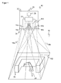
- FIG. 1 shows in a schematic three-dimensional representation of the general structure of a 3D security camera according to the invention 10 according to the stereoscopic principle, which is used for safety monitoring of a room area 12.
- Two camera modules are mounted in a known fixed distance from each other and each take pictures of the space area 12.
- an image sensor 14a, 14b is provided, usually a matrix-shaped recording chip, which receives a rectangular pixel image, for example a CCD or a CMOS sensor.
- an objective with imaging optics which are shown as lenses 16a, 16b and can be realized in practice as any known imaging objective.
- the viewing angle of these optics is in FIG. 1 represented by dashed lines, each forming a viewing pyramid 18a, 18b.
- a lighting unit 100 is shown, this spatial arrangement is to be understood only as an example and the lighting unit may also be arranged asymmetrically or even outside the security camera 3D.
- the illumination unit 100 according to the invention generates a structured illumination pattern, homogeneous illumination or illumination with a different desired intensity distribution in an illumination area 102 in the spatial area 12, and will be described below in various embodiments in connection with FIGS FIGS. 2 to 10 explained in more detail.
- a controller 22 is connected to the two image sensors 14a, 14b and the illumination unit 100.
- the controller 22 controls the lighting unit 100 and, on the other hand, receives image data of the image sensors 14a, 14b. From these image data the controller 22 computes three-dimensional image data (range image, depth map) of the spatial region 12 by means of stereoscopic disparity estimation.
- the illumination pattern provides good contrast and, especially if it is self-similar, a unique structure of each pixel in the illuminated spatial region 12. The most important The aspect of self-dissimilarity is the at least local, better global lack of translational symmetries, so that no apparent shifts of picture elements in the images respectively taken from different perspectives are recognized due to the same illumination pattern elements that would cause errors in the disparity estimation.
- the space area 12 monitored by the 3D security camera 10 may contain known and unexpected objects. This may be, for example, a robot arm 24, a machine, an operator and others.
- the room area 12 provides access to a source of danger, be it because it is an access area or because a dangerous machine 24 is in the room area 12 itself.
- one or more virtual protection and warning fields 26 may be configured. They form a virtual fence around the dangerous machine 24. Due to the three-dimensional evaluation, it is possible to define protection and warning fields 26 three-dimensionally, so that a great flexibility arises.
- the controller 22 evaluates the three-dimensional image data for impermissible interventions.
- the evaluation rules may stipulate that no object may exist in protected fields at all. More flexible evaluation rules provide differentiation between allowed and non-permitted objects, such as trajectories, patterns or contours, speeds or general workflows that are both learned in advance as well as evaluated on the basis of assessments, heuristics or classifications during operation.
- a warning or shutdown device 28 which in turn can be integrated in the controller 22, issues a warning or safeguards the source of danger, for example the robot arm 24 is stopped.
- Safety-related signals in particular the shutdown signal, are output via a safety output 30 (OSSD, Output Signal Switching Device). It depends on the application, whether a warning is sufficient, or it is a two-stage hedge provided in the first warned and only with continued object engagement or even deeper penetration is switched off. Instead of a shutdown, the appropriate response may also be the immediate transfer to a safe parking position.
- the 3D security camera 10 is surrounded by a housing 32 and protected. Through a front screen 34, light can pass in and out of the space area 12.
- the 3D safety camera 10 is designed to be fail-safe. Among other things, this means that the 3D security camera 10 can test itself, even in cycles below the required response time, in particular also detects defects of the illumination unit 100 and thus ensures that the illumination pattern is available in an expected minimum intensity, and that the security output 30 and the warning or shutdown 26 safe, for example, two channels are designed. Likewise, the controller 22 is self-confident, thus evaluating two-channel or uses algorithms that can check themselves. Such regulations are standardized for general non-contact protective devices in EN 61496-1 or IEC 61496 as well as in DIN EN ISO 13849 and EN 61508. A corresponding standard for security cameras is in preparation.
- the invention is explained using the example of the 3D security camera 10.
- the lighting unit 100 can also be used for other cameras, other sensors or in other applications.
- FIG. 2 shows a simplified plan view of a lighting unit 100 according to the invention.
- a laser bar 104 has a plurality of individual emitters 106, which are arranged in a row.
- other semiconductor light sources for example LEDs or single-emitter lasers, can in principle also be used; the optics described below then work in the same way.
- a laser bar 104 is a particularly inexpensive, high-performance source of coherent light.
- the slow axis of the single emitter 106 forms an in FIG. 2 X axis called first axis.
- Emissive light beams 108 are collimated in the X-axis by a microlens array 110.
- the intensity distribution 114 of the individual light bundles 108 as well as the superimposition 116 of all the individual intensity distributions 114 are shown above the resulting illumination line 112.
- the gaussian drop of the intensity distributions 114 as well as the collimation is exaggerated. In practice, the individual intensity distributions 114 are wider and thus themselves line-shaped.
- the fast axis of the laser bar 104 is in FIG. 2 perpendicular to the paper plane.
- this second axis referred to as the Y-axis
- the beams 108 of the individual emitters 106 are collimated by an internal optics (not shown).
- the thickness of the illumination line 112 is ultimately adjusted.
- FIG. 2 how a plurality of illumination lines are superimposed by a microlens array 110 in a first step to form a homogeneous common illumination line.
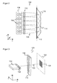
- FIG. 3 shows a three-dimensional representation of the illumination unit 100, in which case as in the following like reference numerals designate the same features.
- the individual lenses 118 of the microlens array 110 are elongated spherical cylindrical lenses whose optically effective curvature provides for collimation in the slow axis.
- the lenses 118 are aligned substantially parallel to one another, but at the same time tilted relative to one another in the plane spanned by the Y axis and the Z axis coinciding with the optical axis 120 of the illumination unit 100.
- This tilting increases, as viewed from the laser bar 104, from left to right, for example, with tiltings of -1 °, -0.5 °, 0 °, 0.5 ° and 1 ° for the five illustrated lenses 118.
- the tilt angle of two adjacent lenses 118 is thus 0.5 °.
- Other, even irregularly distributed and not monotonically increasing or decreasing tilt angle are conceivable.
- a rectangular illumination field 124 then forms on a fictitious projection plane 122 shortly behind the illumination unit 100.
- the extent of the opening angle of the individual emitter 106 in the X direction, the slow axis, and the curvature or focal length of the lenses 118 is determined. This determines the length of the lighting lines.
- the expansion results from the tilt angles.
- Each lens 118 deflects an associated line of illumination of a single emitter 106 in the Y direction. From the lighting lines thus arranged one above the other, the illumination field 124 is composed.
- the lens properties of the microlens array 110 thus cause the beam shaping of the individual emitter 106 to a line of illumination 112, while the tilting this illumination line 112 mitigates to the flat, rectangular illumination field 124.
- FIG. 4 shows an embodiment in which the two optical effects are separated in reality and are generated by their own optical elements.
- the microlens array 110a is planar here and thus does not deflect the illumination lines in the Y direction. This occurs only in a pre- or subordinate prism or keel field 126. It consists for example of mutually tilted wedges 128 made of glass or other optical material. Each wedge 128 has a different wedge angle analogous to the tilt angles in the microlens array 110 of FIG FIG. 3 on. Also conceivable is a combination in which a microlens array 110 with tilted lenses 118 is combined with the prism field 126 and thus the deflection in the Y direction is added.
- a homogeneous illumination field 124 is created.
- suitable choice of the individual tilt angles and by supplementing the shape of the lenses 118 with aspherical portions it is possible to perform a targeted redistribution of the light within the illumination field 124 ,
- the vignetting of the receiving optics 116 or losses due to grazing incidence of the light can be partially compensated.
- This homogeneous illumination field 124 is used to project a pattern in the space area 12.
- This homogeneous illumination field 124 is used to project a pattern in the space area 12.
- the microlens array 110 with tilted lenses 118 is shown here, another embodiment having a planar microlens array 118 and a prism array 126 operates quite analogously.
- An imaging lens 130 which may be embodied as a convex cylindrical lens, collects the individually differently deflected ray bundles 108 and images them off in a focal plane a few centimeters behind the laser bar 104. In the rear focal plane of the imaging lens 130 thus the homogeneous light distribution is generated.
- the homogeneous illumination field 124 is projected through a phase element 132 into the spatial region 12.
- the phase element 132 is for example a phase plate with bumps formed over the area in which it is illuminated by the illumination field 124.
- a self-similar, structured illumination pattern 134 is created in the spatial region 12. In order to generate these interference effects, the coherence of the light of the laser bar 104 should be preserved.
- FIGS. 6 to 8 show in three-dimensional views from different perspectives a representation of the microlens array 110.
- the individual lenses 118 are shown simplified without curvature in order to better recognize the tilt angle.
- At the back further optical elements, such as the imaging lens 130, can be directly connected to this block in order to at least largely avoid an air gap and nevertheless to set the desired distance.
- the Figures 9 and 10 show simulation results of the illumination line 112 and the illumination field 124, respectively FIG. 9 Accordingly, the tilt angle is set to 0 °, so that only one illumination line 112 is formed. In FIG. 10 On the other hand, a finite tilt angle is set.
- the illumination lines belonging to a respective single emitter 106 are offset from one another in the Y direction and together form a rectangular illumination field 124 of high homogeneity. About the amount of tilt angle, the aspect ratios are changeable.
- the individual emitters 106 have a small distance to one another, however, the individual illumination lines that make up the illumination field 124 are slightly shifted from one another.
- the illumination field 124 thereby becomes slightly diamond-shaped. It is conceivable to make a compensating shear, for example by additional tilting of the lenses 118 in the plane spanned by the X-axis and Y-axis, or by another prism field. Practically this is only necessary in particularly demanding applications, since the rhombic effect is often very small and the shear entails the risk of additional optical disturbances or losses.
- the invention enables the defined redistribution of the light of a laser bar 104 into a homogeneous, rectangular light field 124 of variably adjustable aspect ratios with the aid of simple microstructure elements.
- laser bars 104 can be used as the illumination source of a lighting device 100 for a camera sensor 10.
- the illuminated field of a laser bar 104 is adapted to the projection field of a laser illumination.
- the losses are kept low and achieved a high illumination homogeneity.
- the microstructure elements 110, 110a and 126 are very cost-effective and simple to manufacture, since a casting mold can be produced once and the microstructure element 110, 110a and 126 can be molded from it in any desired number.
Landscapes
- Engineering & Computer Science (AREA)
- General Engineering & Computer Science (AREA)
- Physics & Mathematics (AREA)
- General Physics & Mathematics (AREA)
- Mechanical Engineering (AREA)
- Computer Vision & Pattern Recognition (AREA)
- Optics & Photonics (AREA)
- Length Measuring Devices By Optical Means (AREA)
- Stereoscopic And Panoramic Photography (AREA)
- Studio Devices (AREA)
Priority Applications (2)
| Application Number | Priority Date | Filing Date | Title |
|---|---|---|---|
| EP09166515A EP2280239B1 (fr) | 2009-07-27 | 2009-07-27 | Dispositif d'éclairage pour l'éclairage d'une zone de surveillance |
| AT09166515T ATE514050T1 (de) | 2009-07-27 | 2009-07-27 | Beleuchtungsvorrichtung zur beleuchtung eines überwachungsbereichs |
Applications Claiming Priority (1)
| Application Number | Priority Date | Filing Date | Title |
|---|---|---|---|
| EP09166515A EP2280239B1 (fr) | 2009-07-27 | 2009-07-27 | Dispositif d'éclairage pour l'éclairage d'une zone de surveillance |
Publications (2)
| Publication Number | Publication Date |
|---|---|
| EP2280239A1 true EP2280239A1 (fr) | 2011-02-02 |
| EP2280239B1 EP2280239B1 (fr) | 2011-06-22 |
Family
ID=41170109
Family Applications (1)
| Application Number | Title | Priority Date | Filing Date |
|---|---|---|---|
| EP09166515A Active EP2280239B1 (fr) | 2009-07-27 | 2009-07-27 | Dispositif d'éclairage pour l'éclairage d'une zone de surveillance |
Country Status (2)
| Country | Link |
|---|---|
| EP (1) | EP2280239B1 (fr) |
| AT (1) | ATE514050T1 (fr) |
Cited By (8)
| Publication number | Priority date | Publication date | Assignee | Title |
|---|---|---|---|---|
| DE102011052802A1 (de) * | 2011-08-18 | 2013-02-21 | Sick Ag | 3D-Kamera und Verfahren zur Überwachung eines Raumbereichs |
| EP2620894A1 (fr) * | 2012-01-26 | 2013-07-31 | Sick AG | Capteur optoélectronique et procédé de détection d'informations d'objets |
| DE102013002399A1 (de) * | 2013-02-13 | 2014-08-14 | Otto-Von Guericke-Universität Magdeburg Technologie-Transfer-Zentrum | Vorrichtung zur Generierung von Lichtmustern mit einer eindimensional fokussierten Beleuchtungseinrichtung |
| DE102013103251A1 (de) * | 2013-03-28 | 2014-10-16 | Data M Sheet Metal Solutions Gmbh | Erhöhung der Messgenauigkeit bei einer Vermessung mit Lichtschnittsensoren durch gleichzeitige Kalibrierung und Vermeidung von Speckles |
| DE102013214997A1 (de) * | 2013-07-31 | 2015-02-05 | Siemens Aktiengesellschaft | Anordnung zur dreidimensionalen Erfassung eines länglichen Innenraumes |
| DE102014119126B3 (de) * | 2014-12-19 | 2015-08-06 | Sick Ag | Streifenprojektor zum Beleuchten einer Szenerie mit einem veränderlichen Streifenmuster |
| WO2016026733A1 (fr) * | 2014-08-19 | 2016-02-25 | Siemens Aktiengesellschaft | Projecteur |
| CN112596332A (zh) * | 2020-12-23 | 2021-04-02 | 广景视睿科技(深圳)有限公司 | 一种投影系统及投影仪 |
Citations (6)
| Publication number | Priority date | Publication date | Assignee | Title |
|---|---|---|---|---|
| JPS60242419A (ja) * | 1985-04-19 | 1985-12-02 | Ricoh Co Ltd | インプリズムレンズアレイ |
| US5139609A (en) | 1991-02-11 | 1992-08-18 | The Aerospace Corporation | Apparatus and method for longitudinal diode bar pumping of solid state lasers |
| EP1742168A1 (fr) | 2005-07-05 | 2007-01-10 | Sick Ag | Senseur opto-électronique |
| DE102006001634B3 (de) * | 2006-01-11 | 2007-03-01 | Tropf, Hermann | Erstellung eines Abstandsbildes |
| DE202007010884U1 (de) * | 2007-08-03 | 2007-09-27 | Sick Ag | Überwachungsvorrichtung mit Nachführung des Bildsensors, um ein gefährdendes bewegliches Maschinenteil im Sichtfeld zu halten |
| EP1933167A2 (fr) | 2006-12-15 | 2008-06-18 | Sick Ag | Capteur optoélectronique et procédé de détection et de détermination des distances d'un objet |
-
2009
- 2009-07-27 AT AT09166515T patent/ATE514050T1/de active
- 2009-07-27 EP EP09166515A patent/EP2280239B1/fr active Active
Patent Citations (6)
| Publication number | Priority date | Publication date | Assignee | Title |
|---|---|---|---|---|
| JPS60242419A (ja) * | 1985-04-19 | 1985-12-02 | Ricoh Co Ltd | インプリズムレンズアレイ |
| US5139609A (en) | 1991-02-11 | 1992-08-18 | The Aerospace Corporation | Apparatus and method for longitudinal diode bar pumping of solid state lasers |
| EP1742168A1 (fr) | 2005-07-05 | 2007-01-10 | Sick Ag | Senseur opto-électronique |
| DE102006001634B3 (de) * | 2006-01-11 | 2007-03-01 | Tropf, Hermann | Erstellung eines Abstandsbildes |
| EP1933167A2 (fr) | 2006-12-15 | 2008-06-18 | Sick Ag | Capteur optoélectronique et procédé de détection et de détermination des distances d'un objet |
| DE202007010884U1 (de) * | 2007-08-03 | 2007-09-27 | Sick Ag | Überwachungsvorrichtung mit Nachführung des Bildsensors, um ein gefährdendes bewegliches Maschinenteil im Sichtfeld zu halten |
Cited By (15)
| Publication number | Priority date | Publication date | Assignee | Title |
|---|---|---|---|---|
| EP2560366A3 (fr) * | 2011-08-18 | 2013-03-06 | Sick Ag | Caméra 3D et procédé de surveillance d'un domaine spatial |
| DE102011052802B4 (de) * | 2011-08-18 | 2014-03-13 | Sick Ag | 3D-Kamera und Verfahren zur Überwachung eines Raumbereichs |
| DE102011052802A1 (de) * | 2011-08-18 | 2013-02-21 | Sick Ag | 3D-Kamera und Verfahren zur Überwachung eines Raumbereichs |
| EP2620894A1 (fr) * | 2012-01-26 | 2013-07-31 | Sick AG | Capteur optoélectronique et procédé de détection d'informations d'objets |
| CN103225984A (zh) * | 2012-01-26 | 2013-07-31 | 西克股份公司 | 光电传感器以及用于探测目标物信息的方法 |
| DE102013002399B4 (de) * | 2013-02-13 | 2016-12-22 | Chromasens Gmbh | Vorrichtung zur Generierung von Lichtmustern mit einer eindimensional fokussierten Beleuchtungseinrichtung |
| DE102013002399A1 (de) * | 2013-02-13 | 2014-08-14 | Otto-Von Guericke-Universität Magdeburg Technologie-Transfer-Zentrum | Vorrichtung zur Generierung von Lichtmustern mit einer eindimensional fokussierten Beleuchtungseinrichtung |
| DE102013103251A1 (de) * | 2013-03-28 | 2014-10-16 | Data M Sheet Metal Solutions Gmbh | Erhöhung der Messgenauigkeit bei einer Vermessung mit Lichtschnittsensoren durch gleichzeitige Kalibrierung und Vermeidung von Speckles |
| DE102013103251B4 (de) * | 2013-03-28 | 2016-05-12 | Data M Sheet Metal Solutions Gmbh | Erhöhung der Messgenauigkeit bei einer Vermessung mit Lichtschnittsensoren durch gleichzeitige Kalibrierung und Vermeidung von Speckles |
| DE102013214997A1 (de) * | 2013-07-31 | 2015-02-05 | Siemens Aktiengesellschaft | Anordnung zur dreidimensionalen Erfassung eines länglichen Innenraumes |
| WO2016026733A1 (fr) * | 2014-08-19 | 2016-02-25 | Siemens Aktiengesellschaft | Projecteur |
| DE102014216390A1 (de) * | 2014-08-19 | 2016-02-25 | Siemens Aktiengesellschaft | Projektor |
| DE102014119126B3 (de) * | 2014-12-19 | 2015-08-06 | Sick Ag | Streifenprojektor zum Beleuchten einer Szenerie mit einem veränderlichen Streifenmuster |
| CN112596332A (zh) * | 2020-12-23 | 2021-04-02 | 广景视睿科技(深圳)有限公司 | 一种投影系统及投影仪 |
| CN112596332B (zh) * | 2020-12-23 | 2022-03-11 | 广景视睿科技(深圳)有限公司 | 一种投影系统及投影仪 |
Also Published As
| Publication number | Publication date |
|---|---|
| EP2280239B1 (fr) | 2011-06-22 |
| ATE514050T1 (de) | 2011-07-15 |
Similar Documents
| Publication | Publication Date | Title |
|---|---|---|
| EP2280239B1 (fr) | Dispositif d'éclairage pour l'éclairage d'une zone de surveillance | |
| EP2560366B1 (fr) | Caméra 3D et procédé de surveillance d'une pièce | |
| EP2772676B1 (fr) | Caméra 3D et procédé de surveillance tridimensionnel d'un domaine de surveillance | |
| EP2202994B1 (fr) | Caméra 3D pour la surveillance de pièces | |
| EP3403393B1 (fr) | Dispositifs imageurs à plusieurs ouvertures, leur procédé de fabrication et système imageur | |
| EP2166305B1 (fr) | Unité d'éclairage et procédé de projection d'un motif d'éclairage | |
| EP1933167B1 (fr) | Capteur optoélectronique et procédé correspondant de détection et de détermination de la distance d'un objet | |
| EP2469300B1 (fr) | Caméra 3D et procédé de surveillance tridimensionnel d'un domaine de surveillance | |
| DE102015215836B4 (de) | Multiaperturabbildungsvorrichtung mit einer reflektierende Facetten aufweisenden Strahlumlenkvorrichtung | |
| DE102009031732B3 (de) | Entfernungsmessender optoelektronischer Sensor | |
| EP2835973B1 (fr) | Caméra 3D et un procédé de capture de données d'image tridimensionnelles | |
| DE102013105105B3 (de) | 3D-Kamera mit mindestens einer Beleuchtungsvorrichtung | |
| DE202008013217U1 (de) | Beleuchtung zur Erzeugung eines Kontrastmusters | |
| EP4282558B1 (fr) | Étalonnage automatisé d'un dispositif de fabrication additive entièrement parallèle d'un composant à champs de travail combinés | |
| DE102015215845A1 (de) | Multiaperturabbildungsvorrichtung mit kanalindividueller Einstellbarkeit | |
| DE202008017729U1 (de) | Dreidimensionale Überwachung und Absicherung eines Raumbereichs | |
| DE102019123702A1 (de) | Koaxialer Aufbau für Lichterfassungs- und -abstandserfassungs-(LIDAR)-Messungen | |
| EP1931133A1 (fr) | Procédé et dispositif d'acquisition optique d'une structure | |
| EP2199737B1 (fr) | Unité d'éclairage pour caméra 3d | |
| DE102007048681B4 (de) | Linien-Beleuchtungsvorrichtung für einen Sensor | |
| DE102010036852B4 (de) | Stereokamera | |
| DE202012101965U1 (de) | Stereokamera | |
| EP2270424B1 (fr) | Capteur optoélectronique et procédé de surveillance | |
| EP2860714B1 (fr) | Dispositif optoélectronique et procédé de surveillance d'une zone de surveillance | |
| WO2018228912A1 (fr) | Dispositif formant tête de balayage et procédé de réflexion ou de transmission de faisceaux pour scanner, dispositif de balayage muni d'un dispositif formant tête de balayage et scanner muni d'un dispositif formant tête de balayage |
Legal Events
| Date | Code | Title | Description |
|---|---|---|---|
| PUAI | Public reference made under article 153(3) epc to a published international application that has entered the european phase |
Free format text: ORIGINAL CODE: 0009012 |
|
| 17P | Request for examination filed |
Effective date: 20100521 |
|
| AK | Designated contracting states |
Kind code of ref document: A1 Designated state(s): AT BE BG CH CY CZ DE DK EE ES FI FR GB GR HR HU IE IS IT LI LT LU LV MC MK MT NL NO PL PT RO SE SI SK SM TR |
|
| AX | Request for extension of the european patent |
Extension state: AL BA RS |
|
| GRAP | Despatch of communication of intention to grant a patent |
Free format text: ORIGINAL CODE: EPIDOSNIGR1 |
|
| RTI1 | Title (correction) |
Free format text: ILLUMINATION DEVICE FOR ILLUMINATING A MONITORED AREA |
|
| GRAS | Grant fee paid |
Free format text: ORIGINAL CODE: EPIDOSNIGR3 |
|
| GRAA | (expected) grant |
Free format text: ORIGINAL CODE: 0009210 |
|
| AK | Designated contracting states |
Kind code of ref document: B1 Designated state(s): AT BE BG CH CY CZ DE DK EE ES FI FR GB GR HR HU IE IS IT LI LT LU LV MC MK MT NL NO PL PT RO SE SI SK SM TR |
|
| REG | Reference to a national code |
Ref country code: GB Ref legal event code: FG4D Free format text: NOT ENGLISH |
|
| REG | Reference to a national code |
Ref country code: CH Ref legal event code: EP |
|
| REG | Reference to a national code |
Ref country code: IE Ref legal event code: FG4D Free format text: LANGUAGE OF EP DOCUMENT: GERMAN |
|
| REG | Reference to a national code |
Ref country code: DE Ref legal event code: R096 Ref document number: 502009000823 Country of ref document: DE Effective date: 20110811 |
|
| REG | Reference to a national code |
Ref country code: NL Ref legal event code: VDEP Effective date: 20110622 |
|
| PG25 | Lapsed in a contracting state [announced via postgrant information from national office to epo] |
Ref country code: SE Free format text: LAPSE BECAUSE OF FAILURE TO SUBMIT A TRANSLATION OF THE DESCRIPTION OR TO PAY THE FEE WITHIN THE PRESCRIBED TIME-LIMIT Effective date: 20110622 Ref country code: LT Free format text: LAPSE BECAUSE OF FAILURE TO SUBMIT A TRANSLATION OF THE DESCRIPTION OR TO PAY THE FEE WITHIN THE PRESCRIBED TIME-LIMIT Effective date: 20110622 Ref country code: HR Free format text: LAPSE BECAUSE OF FAILURE TO SUBMIT A TRANSLATION OF THE DESCRIPTION OR TO PAY THE FEE WITHIN THE PRESCRIBED TIME-LIMIT Effective date: 20110622 Ref country code: NO Free format text: LAPSE BECAUSE OF FAILURE TO SUBMIT A TRANSLATION OF THE DESCRIPTION OR TO PAY THE FEE WITHIN THE PRESCRIBED TIME-LIMIT Effective date: 20110922 |
|
| PG25 | Lapsed in a contracting state [announced via postgrant information from national office to epo] |
Ref country code: FI Free format text: LAPSE BECAUSE OF FAILURE TO SUBMIT A TRANSLATION OF THE DESCRIPTION OR TO PAY THE FEE WITHIN THE PRESCRIBED TIME-LIMIT Effective date: 20110622 Ref country code: GR Free format text: LAPSE BECAUSE OF FAILURE TO SUBMIT A TRANSLATION OF THE DESCRIPTION OR TO PAY THE FEE WITHIN THE PRESCRIBED TIME-LIMIT Effective date: 20110923 Ref country code: SI Free format text: LAPSE BECAUSE OF FAILURE TO SUBMIT A TRANSLATION OF THE DESCRIPTION OR TO PAY THE FEE WITHIN THE PRESCRIBED TIME-LIMIT Effective date: 20110622 Ref country code: LV Free format text: LAPSE BECAUSE OF FAILURE TO SUBMIT A TRANSLATION OF THE DESCRIPTION OR TO PAY THE FEE WITHIN THE PRESCRIBED TIME-LIMIT Effective date: 20110622 Ref country code: CY Free format text: LAPSE BECAUSE OF FAILURE TO SUBMIT A TRANSLATION OF THE DESCRIPTION OR TO PAY THE FEE WITHIN THE PRESCRIBED TIME-LIMIT Effective date: 20110622 |
|
| PG25 | Lapsed in a contracting state [announced via postgrant information from national office to epo] |
Ref country code: MT Free format text: LAPSE BECAUSE OF FAILURE TO SUBMIT A TRANSLATION OF THE DESCRIPTION OR TO PAY THE FEE WITHIN THE PRESCRIBED TIME-LIMIT Effective date: 20110622 Ref country code: NL Free format text: LAPSE BECAUSE OF FAILURE TO SUBMIT A TRANSLATION OF THE DESCRIPTION OR TO PAY THE FEE WITHIN THE PRESCRIBED TIME-LIMIT Effective date: 20110622 |
|
| REG | Reference to a national code |
Ref country code: IE Ref legal event code: FD4D |
|
| BERE | Be: lapsed |
Owner name: SICK A.G. Effective date: 20110731 |
|
| PG25 | Lapsed in a contracting state [announced via postgrant information from national office to epo] |
Ref country code: IS Free format text: LAPSE BECAUSE OF FAILURE TO SUBMIT A TRANSLATION OF THE DESCRIPTION OR TO PAY THE FEE WITHIN THE PRESCRIBED TIME-LIMIT Effective date: 20111022 Ref country code: PT Free format text: LAPSE BECAUSE OF FAILURE TO SUBMIT A TRANSLATION OF THE DESCRIPTION OR TO PAY THE FEE WITHIN THE PRESCRIBED TIME-LIMIT Effective date: 20111024 Ref country code: EE Free format text: LAPSE BECAUSE OF FAILURE TO SUBMIT A TRANSLATION OF THE DESCRIPTION OR TO PAY THE FEE WITHIN THE PRESCRIBED TIME-LIMIT Effective date: 20110622 Ref country code: CZ Free format text: LAPSE BECAUSE OF FAILURE TO SUBMIT A TRANSLATION OF THE DESCRIPTION OR TO PAY THE FEE WITHIN THE PRESCRIBED TIME-LIMIT Effective date: 20110622 Ref country code: IE Free format text: LAPSE BECAUSE OF FAILURE TO SUBMIT A TRANSLATION OF THE DESCRIPTION OR TO PAY THE FEE WITHIN THE PRESCRIBED TIME-LIMIT Effective date: 20110622 |
|
| PG25 | Lapsed in a contracting state [announced via postgrant information from national office to epo] |
Ref country code: PL Free format text: LAPSE BECAUSE OF FAILURE TO SUBMIT A TRANSLATION OF THE DESCRIPTION OR TO PAY THE FEE WITHIN THE PRESCRIBED TIME-LIMIT Effective date: 20110622 Ref country code: SK Free format text: LAPSE BECAUSE OF FAILURE TO SUBMIT A TRANSLATION OF THE DESCRIPTION OR TO PAY THE FEE WITHIN THE PRESCRIBED TIME-LIMIT Effective date: 20110622 Ref country code: MC Free format text: LAPSE BECAUSE OF NON-PAYMENT OF DUE FEES Effective date: 20110731 |
|
| PLBE | No opposition filed within time limit |
Free format text: ORIGINAL CODE: 0009261 |
|
| STAA | Information on the status of an ep patent application or granted ep patent |
Free format text: STATUS: NO OPPOSITION FILED WITHIN TIME LIMIT |
|
| PG25 | Lapsed in a contracting state [announced via postgrant information from national office to epo] |
Ref country code: BE Free format text: LAPSE BECAUSE OF NON-PAYMENT OF DUE FEES Effective date: 20110731 |
|
| REG | Reference to a national code |
Ref country code: FR Ref legal event code: ST Effective date: 20120406 |
|
| 26N | No opposition filed |
Effective date: 20120323 |
|
| PG25 | Lapsed in a contracting state [announced via postgrant information from national office to epo] |
Ref country code: DK Free format text: LAPSE BECAUSE OF FAILURE TO SUBMIT A TRANSLATION OF THE DESCRIPTION OR TO PAY THE FEE WITHIN THE PRESCRIBED TIME-LIMIT Effective date: 20110622 |
|
| REG | Reference to a national code |
Ref country code: DE Ref legal event code: R097 Ref document number: 502009000823 Country of ref document: DE Effective date: 20120323 |
|
| PG25 | Lapsed in a contracting state [announced via postgrant information from national office to epo] |
Ref country code: FR Free format text: LAPSE BECAUSE OF NON-PAYMENT OF DUE FEES Effective date: 20110822 |
|
| PG25 | Lapsed in a contracting state [announced via postgrant information from national office to epo] |
Ref country code: MK Free format text: LAPSE BECAUSE OF FAILURE TO SUBMIT A TRANSLATION OF THE DESCRIPTION OR TO PAY THE FEE WITHIN THE PRESCRIBED TIME-LIMIT Effective date: 20110622 |
|
| PG25 | Lapsed in a contracting state [announced via postgrant information from national office to epo] |
Ref country code: ES Free format text: LAPSE BECAUSE OF FAILURE TO SUBMIT A TRANSLATION OF THE DESCRIPTION OR TO PAY THE FEE WITHIN THE PRESCRIBED TIME-LIMIT Effective date: 20111003 Ref country code: SM Free format text: LAPSE BECAUSE OF FAILURE TO SUBMIT A TRANSLATION OF THE DESCRIPTION OR TO PAY THE FEE WITHIN THE PRESCRIBED TIME-LIMIT Effective date: 20110622 |
|
| PG25 | Lapsed in a contracting state [announced via postgrant information from national office to epo] |
Ref country code: LU Free format text: LAPSE BECAUSE OF NON-PAYMENT OF DUE FEES Effective date: 20110727 |
|
| PG25 | Lapsed in a contracting state [announced via postgrant information from national office to epo] |
Ref country code: BG Free format text: LAPSE BECAUSE OF FAILURE TO SUBMIT A TRANSLATION OF THE DESCRIPTION OR TO PAY THE FEE WITHIN THE PRESCRIBED TIME-LIMIT Effective date: 20110922 |
|
| PG25 | Lapsed in a contracting state [announced via postgrant information from national office to epo] |
Ref country code: TR Free format text: LAPSE BECAUSE OF FAILURE TO SUBMIT A TRANSLATION OF THE DESCRIPTION OR TO PAY THE FEE WITHIN THE PRESCRIBED TIME-LIMIT Effective date: 20110622 |
|
| PG25 | Lapsed in a contracting state [announced via postgrant information from national office to epo] |
Ref country code: HU Free format text: LAPSE BECAUSE OF FAILURE TO SUBMIT A TRANSLATION OF THE DESCRIPTION OR TO PAY THE FEE WITHIN THE PRESCRIBED TIME-LIMIT Effective date: 20110622 |
|
| GBPC | Gb: european patent ceased through non-payment of renewal fee |
Effective date: 20130727 |
|
| PG25 | Lapsed in a contracting state [announced via postgrant information from national office to epo] |
Ref country code: GB Free format text: LAPSE BECAUSE OF NON-PAYMENT OF DUE FEES Effective date: 20130727 |
|
| REG | Reference to a national code |
Ref country code: AT Ref legal event code: MM01 Ref document number: 514050 Country of ref document: AT Kind code of ref document: T Effective date: 20140727 |
|
| PG25 | Lapsed in a contracting state [announced via postgrant information from national office to epo] |
Ref country code: AT Free format text: LAPSE BECAUSE OF NON-PAYMENT OF DUE FEES Effective date: 20140727 |
|
| PGFP | Annual fee paid to national office [announced via postgrant information from national office to epo] |
Ref country code: GB Payment date: 20170823 Year of fee payment: 17 Ref country code: CH Payment date: 20170724 Year of fee payment: 9 |
|
| REG | Reference to a national code |
Ref country code: CH Ref legal event code: PL |
|
| PG25 | Lapsed in a contracting state [announced via postgrant information from national office to epo] |
Ref country code: LI Free format text: LAPSE BECAUSE OF NON-PAYMENT OF DUE FEES Effective date: 20180731 Ref country code: CH Free format text: LAPSE BECAUSE OF NON-PAYMENT OF DUE FEES Effective date: 20180731 |
|
| PG25 | Lapsed in a contracting state [announced via postgrant information from national office to epo] |
Ref country code: IT Free format text: LAPSE BECAUSE OF NON-PAYMENT OF DUE FEES Effective date: 20180727 |
|
| PGFP | Annual fee paid to national office [announced via postgrant information from national office to epo] |
Ref country code: DE Payment date: 20190723 Year of fee payment: 11 |
|
| REG | Reference to a national code |
Ref country code: DE Ref legal event code: R119 Ref document number: 502009000823 Country of ref document: DE |
|
| PG25 | Lapsed in a contracting state [announced via postgrant information from national office to epo] |
Ref country code: DE Free format text: LAPSE BECAUSE OF NON-PAYMENT OF DUE FEES Effective date: 20210202 |