EP2280335A2 - Appareil de détection de la position optique et appareil d'affichage doté de la fonction de détection de la position - Google Patents
Appareil de détection de la position optique et appareil d'affichage doté de la fonction de détection de la position Download PDFInfo
- Publication number
- EP2280335A2 EP2280335A2 EP10171214A EP10171214A EP2280335A2 EP 2280335 A2 EP2280335 A2 EP 2280335A2 EP 10171214 A EP10171214 A EP 10171214A EP 10171214 A EP10171214 A EP 10171214A EP 2280335 A2 EP2280335 A2 EP 2280335A2
- Authority
- EP
- European Patent Office
- Prior art keywords
- position detection
- light
- guide plate
- light guide
- lights
- Prior art date
- Legal status (The legal status is an assumption and is not a legal conclusion. Google has not performed a legal analysis and makes no representation as to the accuracy of the status listed.)
- Withdrawn
Links
Images




Classifications
-
- G—PHYSICS
- G01—MEASURING; TESTING
- G01B—MEASURING LENGTH, THICKNESS OR SIMILAR LINEAR DIMENSIONS; MEASURING ANGLES; MEASURING AREAS; MEASURING IRREGULARITIES OF SURFACES OR CONTOURS
- G01B11/00—Measuring arrangements characterised by the use of optical techniques
- G01B11/14—Measuring arrangements characterised by the use of optical techniques for measuring distance or clearance between spaced objects or spaced apertures
-
- G—PHYSICS
- G06—COMPUTING OR CALCULATING; COUNTING
- G06F—ELECTRIC DIGITAL DATA PROCESSING
- G06F3/00—Input arrangements for transferring data to be processed into a form capable of being handled by the computer; Output arrangements for transferring data from processing unit to output unit, e.g. interface arrangements
- G06F3/01—Input arrangements or combined input and output arrangements for interaction between user and computer
- G06F3/03—Arrangements for converting the position or the displacement of a member into a coded form
- G06F3/041—Digitisers, e.g. for touch screens or touch pads, characterised by the transducing means
- G06F3/042—Digitisers, e.g. for touch screens or touch pads, characterised by the transducing means by opto-electronic means
- G06F3/0428—Digitisers, e.g. for touch screens or touch pads, characterised by the transducing means by opto-electronic means by sensing at the edges of the touch surface the interruption of optical paths, e.g. an illumination plane, parallel to the touch surface which may be virtual
Definitions
- the present invention relates to an optical position detection apparatus and a display apparatus having a position detection function that is provided with the optical position detection apparatus.
- a display apparatus having a position detection function in which a touch panel is arranged on the front surface of an image generation apparatus such as a liquid crystal apparatus, has been used recently.
- an input of information is performed while an image displayed on the image generation apparatus is referred to.
- the touch panel as described above is composed of a position detection apparatus for detecting the position of a target object in a detection area.
- a resistive film type As detection types of the position detection apparatus, a resistive film type, an ultrasonic type, a capacitive type, an optical type, and the like, are known.
- the resistive film type is low-cost, but, like the capacitive type, has a low transmissivity.
- the ultrasonic type or the capacitive type has a high response speed, but has a low environmental resistance.
- the optical type has the characteristics of high environmental resistance, high transmissivity, and high response speed (see JP-A-2004-295644 and JP-A-2004-303172 ).
- optical position detection apparatuses as described in JP-A-2004-295644 and JP-A-2004-303172 require light sources or light detectors in the neighborhood of a display screen, the number of which corresponds to the resolution of position coordinates that should be detected, and thus are high-cost.
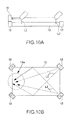
- the inventor of the invention is examining an optical position detection apparatus in which position detection light sources 12 are installed at end portions of a light guide plate 13 to face each other, and a light detector 15 detects a position detection light L2 that is emitted from the light guide plate 13 and reflected by a user's finger and so on.
- the optical position detection apparatus as described above has the advantages that it can detect the position of the finger and so on with a small number of position detection light sources 12 or light detectors 15 if there is a roughly linear relationship between the intensity of the position detection light L2 that is emitted from the light guide plate 13 and the distance from the position detection light source 12 .
- the optical position detection apparatus as illustrated in Figs. 10A and 10B has the problem that when the position of the finger and so on is actually detected by the optical position detection apparatus, a big error may occur.
- the inventor of the invention has newly found that such error is caused by the scattering of the intensity distribution of the position detection light L2 in a detection area.
- An advantage of some aspects of the invention is to provide an optical position detection apparatus and a display apparatus having a position detection function that is provided with the optical position detection apparatus, which can accurately perform the position detection even in the case where a position detection method using the intensity distribution of the position detection lights formed by the light guide plate is adopted.
- an optical position detection apparatus for optically detecting the position of a target object in a detection area, which includes position detection light sources that emit position detection lights irradiated onto the target object; a light guide plate that receives the position detection lights therein and emits the received position detection lights onto the detection area to form an intensity distribution of a light emission quantity of the position detection lights in the detection area; a light detector having light receiving portions arranged toward the detection area to receive the position detection lights that are reflected by the target object; and a signal processing portion that detects the position of the target object based on the intensity distribution of the light emission quantity in the detection area, wherein the light guide plate is so configured that light incident portions for receiving the position detection lights and side portions except for the light incident portions are provided on outer periphery side portions when the light guide plate is seen in a plan view, a light emission surface that emits the position detection lights incident from the light incident portions toward the detection area is provided on a plane portion when the light guide plate is seen in a plan view,
- the reflected light is detected by the light detector.
- the position of the target object can be detected from a light receiving intensity that is obtained through the light detector. Accordingly, it is not necessary to arrange a plurality of optical devices along the detection area, and thus the position detection apparatus with low cost and with low power consumption can be configured.
- the light guide plate in the outer periphery side portions of the light guide plate, at least a portion of the side portions except for the light incident portions is the anti-reflection surface. Accordingly, the lights from the position detection light sources directly reach the area that is apart from the position detection light sources, but by only this, it is difficult for the lights reflected from the outer periphery side portions of the light guide plate to reach the area. Accordingly, it can be avoided that the light emission intensity of the position detection lights emitted from the area that is apart from the light detection light sources becomes heightened in comparison to that of other areas. In the aspect of the invention, even in the case where the position detection method using the intensity distribution of the position detection lights formed by the light guide plate is adopted, the position detection lights are emitted from the light guide plate with an appropriate intensity distribution, and thus the position detection can be accurately performed.
- the whole surface of the side portion is the anti-reflection surface.
- the reflection of the position detection light can be prevented on the whole outer periphery side portion. Accordingly, since the position detection light is emitted from the light guide plate with more appropriate intensity distribution, the position detection can be performed more accurately.
- the anti-reflection surface is formed by a light absorption layer formed on the side portion. In this configuration, it is not necessary to perform processes that trouble the light guide plate itself, and thus the anti-reflection surface can be easily formed.
- the aspect of the invention When the aspect of the invention is applied to a case in which the light guide plate is in the form of a tetragonal plane, and the light incident portions are provided in portions corresponding to corners of the tetragon, a remarkable effect can be obtained.
- the position detection lights In the case where the light guide plate is tetragonal and the light incident portions are formed on the portions corresponding to corners of the tetragon, it cannot be avoided that the position detection lights are headed toward the outer periphery side portions of the light guide plate.
- the position detection lights are emitted from the light guide plate with an appropriate intensity distribution, and thus the position detection can be performed more accurately.
- the term "tetragon" means a tetragon that further includes a shape in which portions corresponding to corners of the tetragon are cut out.
- the aspect of the invention When the aspect of the invention is applied to a case in which four position detection light sources are provided and in the light guide plate, the light incident portions are provided on portions that correspond to the four corners of the tetragon, a remarkable effect can be obtained. If the above-described configuration is adopted, it cannot be avoided that the position detection lights are headed toward the outer periphery side portions of the light guide plate. However, according to the aspect of the invention, even in the case of using the light guide plate as configured above, the position detection lights are emitted from the light guide plate with an appropriate intensity distribution, and thus the position detection can be performed more accurately.
- the aspect of the invention When the aspect of the invention is applied to a case in which two neighboring position detection light sources among four position detection light sources simultaneously emit the position detection lights, a remarkable effect can be obtained. If the above-described configuration is adopted, it cannot be avoided that the position detection lights are headed toward the outer periphery side portions of the light guide plate. However, according to the aspect of the invention, even in the case of using the light guide plate as configured above, the position detection lights are emitted from the light guide plate with an appropriate intensity distribution, and thus the position detection can be performed more accurately.
- the optical position detection apparatus may be used to configure a display apparatus having a position detection function.
- the display apparatus having the position detection function has an image generation apparatus that forms an image in an overlapping area when the light guide plate is seen in a plan view.
- the image generation apparatus may be a projection display apparatus or a direct-view display apparatus, such as a liquid crystal apparatus, an organic electroluminescence apparatus, or the like.
- the display apparatus having the position detection function according to the aspect of the invention may be used in an electronic appliance, such as a portable phone, car navigation, personal computer, ticket machine, bank terminal, or the like, in addition to various kinds of display apparatuses.
- an electronic appliance such as a portable phone, car navigation, personal computer, ticket machine, bank terminal, or the like, in addition to various kinds of display apparatuses.
- an optical position detection apparatus for optically detecting a position of a target object, which includes a light guide plate having light incident portions provided on four corner portions of an outer periphery portion; four position detection light sources that emit position detection lights toward the light incident portions; a light detector that receives the position detection lights which are emitted from one surface in a thickness direction of the light guide plate and are reflected by the target object; and a signal processing portion that detects the position of the target object based on the result of light received in the light detector, wherein the four position detection light sources emit the position detection lights through alternate light-up by changing a combination of one portion of the position detection light sources and the other portion of the position detection light sources the number of which is equal to that of the one portion of the position detection light sources, and at least a portion of the outer periphery portions of the light guide plate except for the light incident portions is an anti-reflection surface that prevents reflection of the position detection lights in the light guide plate.
- the position detection light that is emitted from one side surface (a light emission surface) in a thickness direction of the light guide plate is reflected by a target object that is arranged on the emission side of the light guide plate
- the reflected light is detected by the light detector.
- a position of the target object can be detected from a light receiving intensity that is obtained through the light detector. Accordingly, it is not necessary to arrange a plurality of optical devices along the detection region, and thus the position detection apparatus with low cost and with low power consumption can be configured.
- the anti-reflection surface in the outer periphery portions of the light guide plate, at least a portion in which the position detection light sources are not arranged is the anti-reflection surface. Accordingly, the lights from the position detection light sources directly reach the area that is apart from the position detection light sources, but it is difficult for the lights reflected from the outer periphery portions of the light guide plate to reach the area. Accordingly, it can be avoided that the light emission intensity of the position detection lights emitted from the area that is apart from the light detection light sources becomes heightened in comparison to that of other areas. In this aspect of the invention, even in the case where the position detection method using the intensity distribution of the position detection lights formed by the light guide plate is adopted, the position detection lights are emitted from the light guide plate with an appropriate intensity distribution, and thus the position detection can be accurately performed.
- the whole portion in which the position detection light sources are not arranged is the anti-reflection surface.
- the reflection of the position detection lights can be prevented in the whole portion in which the position detection light sources are not arranged among the outer periphery portions of the light guide plate. Accordingly, the position detection lights can be emitted from the light guide plate with more appropriate intensity distribution, and thus the position detection can be performed more accurately.
- the anti-reflection surface may adopt a configuration that is formed by a light absorption layer formed on the outer periphery portions of the light guide plate.
- the outer periphery portions of the light guide plate may include the light incident portions provided on four corner portions thereof, and the light detector may adopt a configuration in which the light detector is arranged in an overlapping position in the thickness direction of the light guide plate with the center of the side portion that is interposed between the neighboring two corner portions among the four corner portions.
- the position detection light is composed of infrared rays. In this case, the position detection light is not visually recognized.
- the optical position detection apparatus can be used in a projection display apparatus having a position detection function.
- the light guide plate adopts a configuration in which one surface thereof crosses a direction in which the image is projected.
- the projection display apparatus having the position detection function has the optical position detection apparatus according to the aspect of the invention and an image projection apparatus that projects the image.
- FIGs. 1A and 1B are explanatory views schematically illustrating a configuration of an optical position detection apparatus to which the invention is applied and a display apparatus having a position detection function that is provided with the optical position detection apparatus.
- Figs. 2A to 2C are explanatory views illustrating a detailed configuration of the optical position detection apparatus to which the invention is applied.
- Figs. 3A and 3B are explanatory views illustrating the contents of signal processing in the optical position detection apparatus to which the invention is applied and the display apparatus having the position detection function.
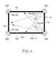
- Fig. 4 is a plan view of a light guide plate that is used in an optical position detection apparatus to which the invention is applied and a display apparatus having position detection function.
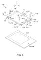
- Fig. 5 is an exploded perspective view of an optical position detection apparatus according to a modified example 1 of the invention.
- Fig. 6 is an explanatory view illustrating a cross-sectional configuration of an optical position detection apparatus according to a modified example 1 of the invention.
- Fig. 7 is an exploded perspective view of an optical position detection apparatus according to a modified example 2 of the invention.
- Fig. 8 is an explanatory view illustrating a cross-sectional configuration of an optical position detection apparatus according to a modified example 2 of the invention.
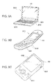
- Figs. 9A to 9C are explanatory views illustrating an electronic appliance using a display apparatus having position detection function according to an aspect of the invention.
- Figs. 10A and 10B are explanatory views illustrating a basic configuration of an optical position detection apparatus.
- a display apparatus 100 having a position detection function as illustrated in Figs. 1A and 1B is provided with an optical position detection apparatus 10 and an image generation apparatus 200.
- the optical position detection apparatus 10 detects the plane position of the target object Ob based on an image that is displayed by the image generation apparatus 200.
- the position detection light L2a from the light incident portion 13a travels within the light guide plate 13 toward the light incident portion 13b, and is gradually emitted from the light emission surface 13s.
- the position detection lights L2c and L2d travel within the light guide plate 13, and are gradually emitted from the light emission surface 13s. Accordingly, if a target object Ob such as a finger is arranged in the detection area 10R, the position detection lights L2a to L2d are reflected by the target object Ob, and a portion of the reflected light is detected by the light detector 15.
- the light quantity of the position detection light L2a that is emitted onto the detection area 10R is linearly attenuated according to the distance from the position detection light source 12A as indicated as a solid line in Fig. 2C
- the light quantity of the position detection light L2b that is emitted onto the detection area 10R is linearly attenuated according to the distance from the position detection light source 12B as indicated as a dotted line in Fig. 2C .
- a signal processing portion 150 is electrically connected to a connection point P1 of the light detector 15 and the resistor 15r.
- a detection signal Vc output from the connection point P1 of the light detector 15 and the resistor 15r is indicated by the following equation.
- Vc V ⁇ 15 V ⁇ 15 + resistance value of the resistor 15 ⁇ r
- the signal processing portion 150 is briefly provided with a position detection signal extraction circuit 190, a position detection signal separation circuit 170, and a light emitting intensity compensation command circuit 180.
- the position detection signal extraction circuit 190 is provided with a filter 192 composed of a capacitor of about lnF, and this filter 192 functions as a high-pass filter that removes a DC component from the signal output from the connection point P1 of the light detector 15 and the resistor 15r. Accordingly, by the filter 192, the position detection signal Vd of the position detection light L2a and L2b by the light detector 15 is extracted from the detection signal Vc output from the connection point P1 of the light detector 15 and the resistor 15r. That is, since the environmental light can be considered to have a constant intensity in a certain period in comparison to the modulated position detection lights L2a and L2b, a low-frequency component or the DC component due to the environmental light is removed by the filter 192.
- the position detection signal extraction circuit 190 has an addition circuit 193 that is provided with a feedback resistor 194 of about 220k ⁇ at the rear end of the filter 192, and the position detection signal Vd extracted by the filter 192 is output to the position detection signal separation circuit 170 as a position detection signal Vs which overlaps a voltage V/2 that is 1/2 of the bias voltage Vb.
- the position detection signal separation circuit 170 is provided with a switch 171 that performs a switching operation in synchronization with a drive pulse that is applied to the position detection light source 12A, a comparator 172, and a capacitor 173 that is electrically connected to input lines of the comparator 172. Accordingly, if the position detection signal Vs is input to the position detection signal separation circuit 170, an effective value Vea of the position detection signal Vs in a period when the position detection light L2a lights up and an effective value Veb of the position detection signal Vs in a period when the position detection light L2b lights up are alternately output from the position detection signal separation circuit 170 to the light emitting intensity compensation command circuit 180.
- the light emitting intensity compensation command circuit 180 heightens the light emission quantity of the position detection light source 12B by lowering the resistance value of the variable resistor 112.
- the following configuration may be adopted in addition to the above-described configuration, in which the four position detection light sources 12A to 12D emit the position detection lights through alternate light-up by changing a combination of one portion of the position detection light sources and the other portion of the position detection light sources the number of which is equal to that of the one portion of the position detection light sources. That is, in the optical position detection apparatus 10 in this embodiment of the invention, the position detection lights for detecting the position in a first direction (X direction) may be generated by driving the position detection light sources 12A and 12D in phase, driving the position detection light sources 12B and 12C in phase, and driving the position detection light sources 12A and 12D and the position detection light sources 12B and 12C in reverse phase.
- the position detection in the long-side direction is performed based on the difference in results of detection by the light detector 15 between the period in which the position detection light sources 12A and 12D light up and the period in which the position detection light sources 12B and 12C light up.
- the position detection in the short-side direction is performed based on the difference in results of detection by the light detector 15 between the period in which the position detection light sources 12A and 12C light up and the period in which the position detection light sources 12B and 12D light up. Even by this method, the influence of the environmental light can be cancelled. Also, if the intensity distribution as illustrated in Fig. 2C corresponds to simple increase or simple decrease, the position detection can be performed even in the case where there is no linear relationship.
- the position of the target object Ob in the Z-axis direction may be detected by making all of the four position detection light sources 12A to 12D light up.
- Fig. 4 is a plan view illustrating the light guide plate 13 that is used in the optical position detection apparatus 10 to which the invention is applied and the display apparatus 100 having the position detection function.
- the optical position detection apparatus 10 is on the assumption that there is a predetermined correlation between the intensity of the position detection lights L2a to L2d emitted from the light guide plate 13 and the distance from the position detection light sources 12A to 12D. However, if a difference in intensity distribution occurs, which has been explained with reference to Fig. 10B , the detection accuracy is deteriorated.
- the whole surface of the side portions 13i, 13j, 13k, and 131, except for the light incident portions 13a to 13d, among the outer periphery side portion 13m of the light guide plate 13 becomes an anti-reflection surface 13v
- the whole surface of the outer periphery side portion 13m of the light guide plate 13 except for the light incident portions 13a to 13d becomes the anti-reflection surface 13v.
- the lights headed toward the side portions 13i, 13j, 13k, and 131 (anti-reflection surface 13v) among the position detection lights L2a to L2d incident from the light incident portions 13a to 13d in the light guide plate 13 are absorbed by the light absorption layer 14, and are not reflected.
- the optical position detection apparatus 10 As described above, in the optical position detection apparatus 10 according to this embodiment and the display apparatus 100 having the position detection function, if the position detection lights L2a to L2d are emitted from the light emission surface 13s of the light guide plate 13 and are reflected by the target object Ob arranged on the emission side of the light guide plate 13, the reflected lights are detected by the light detector 15.
- the position of the target object Ob can be detected from the light receiving intensity obtained through the light detector 15. Accordingly, it is not necessary to arrange a plurality of light elements along the detection region 10R, and thus the position detection apparatus 10 with low cost and with low power consumption can be configured.
- the outer periphery portion 13m except for the light incident portions 13a to 13d in the light guide plate 13 becomes the anti-reflection surface 13v. Accordingly, as illustrated in Fig. 4 , the lights from the position detection light sources 12A to 12D directly reach the area that is apart from the position detection light sources 12A to 12D, but it is difficult for the lights reflected from the outer periphery side portions 13m of the light guide plate 13 to reach the area. Accordingly, it can be avoided that the light emission intensity of the position detection lights emitted from the area that is apart from the light detection light sources 12A to 12D becomes heightened in comparison to that of other areas.
- the position detection lights L2a to L2d are emitted from the light guide plate 13 with an appropriate intensity distribution. Accordingly, in this embodiment of the invention, the position detection can be accurately performed.
- the whole surface of the outer periphery side portion 13m except for the light incident portions 13a to 13d is the anti-reflection surface 13v, the reflection of the position detection lights can be prevented on the whole outer periphery portion 13m. Accordingly, the position detection lights L2a to L2d are emitted from the light guide plate 13 with more appropriate intensity distribution, and thus the position detection can be performed more accurately.
- the position detection can be accurately performed. That is, as illustrated in Fig. 4 , if the two position detection light sources 12A and 12D simultaneously emit the position detection lights L2a and L2d, the lights reflected from the outer periphery side portions 13m of the light guide plate 13 are concentrated, and thus the intensity distribution of the position detection lights L2a to L2d is remarkably scattered.
- the position detection lights are emitted from the light guide plate 13 with an appropriate intensity distribution, and thus the position detection can be performed more accurately.
- the anti-reflection surface 13v is configured by the light absorption layer 14 formed on the outer periphery side portion 13m. Accordingly, it is not necessary to perform processes that trouble the light guide plate 13 itself, and thus the anti-reflection surface 13v can be easily formed.
- the optical position detection apparatus 10 and the display apparatus 100 having a position detection function are not limited to the foregoing embodiments, and various modifications may be made without departing from the scope of the invention.
- the anti-reflection surface 13v is configured by the light absorption layer 14 formed on the outer periphery side portion 13m
- the anti-reflection surface 13v for preventing the reflection by the light scattering may be configured by forming fine concavo-convexes on the outer periphery side portions 13m.
- the anti-reflection surface 13v since the wavelength of the position detection lights L2a to L2d is constant, the anti-reflection surface 13v may also be configured by forming a dielectric multi-layer on the outer periphery side portions 13m.
- the configuration including the projection type display apparatus 203, 207 as the image generation apparatus 200 is explained.
- a direct view type display apparatus is employed as the image generation apparatus 200, it can be used in an electronic apparatus described later with reference to Figs. 10A and 10B .
- Figs. 7 and 8 are explanatory views of the optical position detection apparatus 10 and the display apparatus 100 having position detection function according to the modified example 2 of the invention.
- Fig. 7 and Fig. 8 are an exploded perspective view of the optical position detection apparatus 10 and the display apparatus 100 having position detection function according to the modified example 2 of the invention, and an explanatory view illustrating a cross-sectional configuration thereof, respectively.
- the display apparatus 100 having position detection function in this embodiment since the configuration of the optical position detection apparatus 10 is the same as that of the above-described embodiment, the common parts are designated with the same reference symbols and the explanation thereof will be omitted.
- the display apparatus 100 having position detection function shown in Figs. 7 and 8 includes the optical position detection apparatus 10 and the image generation apparatus 200, and the optical position detection apparatus 10 includes the position detection light source 12 emitting position detection light, the light guide plate 13, and the optical detector 15 having the light receiving portion 15a directed to the detection area 10R.
- the image generation apparatus 200 includes a liquid crystal apparatus 209 which is a direct view type display apparatus and a light transmissive cover 30.
- the liquid crystal apparatus 209 includes an image display area 20R which is overlapped with the light guide plate 13 when seen from the plane, and the image display area 20R overlaps with the detection area 10R when seen from the plane.
- an optical sheet 16 is disposed on the light emitting side of the light guide plate 13 for making the position detection light L2a to L2d uniform, as necessary.
- a first prism sheet 161 opposing the light emitting surface 13s of the light guide plate 13 a second prism sheet 162 opposing the first prism sheet 161 on the side opposite to the side where the light guide plate 13 is located, and a light diffusion plate 163 opposing the second prism sheet 162 on the side opposite to the side where the light guide plate 13 is located.
- a rectangular frame-like light shielding sheet 17 is disposed around the optical sheet 16 on the side opposite to the side where the light guide plate 13 is located with respect to the optical sheet 16. The light shielding sheet 17 prevents the position detection light L2a to L2d emitted from the position detection light sources 12A to 12D from leaking.
- the liquid crystal apparatus 209 (the image generation apparatus 200) includes a liquid crystal panel 209a on the side opposite to the side where the light guide plate 13 is located with respect to the optical sheet 16 (the first prism sheet 161, the second prism sheet 162, and the light diffusion plate 163).
- the liquid crystal panel 209a is a light transmissive liquid crystal panel and has a structure that two light transmissive substrates 21 and 22 are bonded by a sealing material 23 and a liquid crystal 24 is filled between the substrates.
- the liquid crystal panel 209a is an active matrix type liquid crystal panel, in which light transmissive pixel electrodes, data lines, scanning lines, and pixel switching elements (not shown) are formed on one of the two light transmissive substrates 21 and 22, and light transmissive common electrodes (not shown) are formed on the other thereof.
- the pixel electrodes and the common electrodes may be formed on the same substrate.
- orientation of the liquid crystal 24 is controlled in each of a plurality of the pixels, and thus an image is formed in the image display area 20R.
- one light transmissive substrate 21 is provided with a substrate extension 21t which is extended to the periphery from the contour of the other light transmissive substrate 22.
- Electronic components 25 constituting a drive circuit and the like are mounted on the surface of the substrate extension 21t.
- a wiring member 26 such as a flexible printed circuit board (FPC) is connected to the substrate extension 21t. Only the wiring member 26 may be mounted on the surface of the substrate extension 21t.
- a polarization plate (not shown) is disposed on the outer surface side of the light transmissive substrate 21, 22, as necessary.
- the image display area 20R is configured to transmit the position detection light L2a to L2d.
- the liquid crystal panel 209a is disposed on the side opposite to the observation side of the light guide plate 13, it is not necessary to configure such that the image display area 20R transmits the position detection light L2a to L2d.
- the liquid crystal device 209 includes an illuminating device 40 for illuminating the liquid crystal panel 209a.
- the illuminating device 40 is disposed between the light guide plate 13 and the reflection plate 14 at the side of the light guide plate 13 facing the side where the liquid crystal panel 209a is located.
- the illuminating device 40 includes a light source 41 for illumination and a light guide plate 43 for illumination, which emits illumination light emitted from the light source 41 for illumination while making the illumination light propagate.
- the light guide plate 43 for illumination has a rectangular flat shape.
- the light source 41 for illumination is formed by a light emitting element, such as an LED (light emitting diode), and emits, for example, white illumination light L4 in response to a driving signal output from a driving circuit (not shown).
- a plurality of light sources 41 for illumination is arrayed along a side portion 43a of the light guide plate 43 for illumination.
- the illumination light emitted from the light source 41 for illumination is incident from the side portion 43a of the light guide plate 43 for illumination onto the inside of the light guide plate 43 for illumination, propagates through the inside of the light guide plate 43 for illumination toward the outer edge 43b of the opposite side, and then is emitted from the light emitting surface 43s which is one surface.
- the light guide plate 43 for illumination has a light guide structure in which the ratio of light amount of light, which is emitted from the light emitting surface 43s, to internal propagating light, which propagates from the side portion 43a side toward the outer edge 43b on the opposite side, increases steadily.
- this light guide structure is realized by gradually increasing the area of a fine uneven refraction surface for light deflection or light scattering, which is formed on the light emitting surface 43s or the back surface 43t of the light guide plate 43 for illumination, the formation density of the printed scattering layer, and the like toward the internal propagation direction.
- the illumination light L4 incident from the side portion 43a is emitted almost uniformly from the light emitting surface 43s.
- the light guide plate 43 for illumination is disposed so as to overlap the image display area 20R of the liquid crystal panel 209a in plan view at the opposite side of the viewing side of the liquid crystal panel 209a, and functions as a so-called backlight.
- the light guide plate 43 for illumination may be disposed at the viewing side of the liquid crystal panel 209a so as to function as a so-called front light.
- the light guide plate 43 for illumination is disposed between the light guide plate 13 and the reflecting plate 14 in the present embodiment, the light guide plate 43 for illumination may also be disposed between the optical sheet 16 and the light guide plate 13.
- the light guide plate 43 for illumination and the light guide plate 13 may be formed using a common light guide plate.
- the optical sheet 16 is commonly used between the position detection lights L2a to L2d and the illumination light L4.
- an optical sheet for exclusive use may also be disposed at the light emission side of the light guide plate 43 for illumination, separately from the optical sheet 16.
- a light scattering plate which performs a sufficient light scattering operation is used in many cases in order to make uniform the planar luminance of the illumination light L4 emitted from the light emitting surface 43s in the light guide plate 43 for illumination.
- the position detection is interrupted if the position detection light L2a to L2d emitted from the light emitting surface 13s in the light guide plate 13 for position detection is largely scattered.
- the light scattering plate is a dedicated component of the light guide plate 43 for illumination.
- optical sheets with a condensing operation such as a prism sheet (first or second prism sheet 161 or 162) may be commonly used.
- FIG. 9A is a view illustrating the configuration of a mobile type personal computer including a display apparatus 100 having a position detection function.
- a personal computer 2000 includes the display apparatus 100 with a position detection function as a display unit and a main body 2010.
- a power switch 2001 and a keyboard 2002 are provided in the main body 2010.
- Fig. 9B is a view illustrating the configuration of a mobile phone including the display apparatus 100 having a position detection function.
- examples of an electronic apparatus to which the display apparatus 100 having a position detection function is applied include a digital still camera, a liquid crystal television, a view finder type or monitor direct view type video tape recorder, a car navigation system, a pager, an electronic diary, an electronic calculator, a word processor, a workstation, a video phone, a POS terminal, a bank terminal, and the like, as well as those shown in Figs. 9A to 9C .
- the display apparatus 100 having a position detection function described above may be applied as a display unit of each of the various kinds of electronic apparatuses.
Landscapes
- Engineering & Computer Science (AREA)
- General Engineering & Computer Science (AREA)
- Theoretical Computer Science (AREA)
- Physics & Mathematics (AREA)
- General Physics & Mathematics (AREA)
- Human Computer Interaction (AREA)
- Position Input By Displaying (AREA)
- Length Measuring Devices By Optical Means (AREA)
- Measurement Of Optical Distance (AREA)
Applications Claiming Priority (2)
| Application Number | Priority Date | Filing Date | Title |
|---|---|---|---|
| JP2009178777 | 2009-07-31 | ||
| JP2010060335A JP5381833B2 (ja) | 2009-07-31 | 2010-03-17 | 光学式位置検出装置および位置検出機能付き表示装置 |
Publications (2)
| Publication Number | Publication Date |
|---|---|
| EP2280335A2 true EP2280335A2 (fr) | 2011-02-02 |
| EP2280335A3 EP2280335A3 (fr) | 2014-06-11 |
Family
ID=43012557
Family Applications (1)
| Application Number | Title | Priority Date | Filing Date |
|---|---|---|---|
| EP10171214.9A Withdrawn EP2280335A3 (fr) | 2009-07-31 | 2010-07-29 | Appareil de détection de la position optique et appareil d'affichage doté de la fonction de détection de la position |
Country Status (4)
| Country | Link |
|---|---|
| US (3) | US8259309B2 (fr) |
| EP (1) | EP2280335A3 (fr) |
| JP (1) | JP5381833B2 (fr) |
| CN (1) | CN101989155B (fr) |
Cited By (2)
| Publication number | Priority date | Publication date | Assignee | Title |
|---|---|---|---|---|
| EP2565712A1 (fr) * | 2011-09-05 | 2013-03-06 | Ricoh Company, Ltd. | Système de projection, appareil de projection, dispositif de capteur, procédé de commande de génération d'énergie et produit de programme informatique |
| WO2016188760A1 (fr) * | 2015-05-26 | 2016-12-01 | Philips Lighting Holding B.V. | Détermination de la position d'un dispositif portatif par rapport à un luminaire |
Families Citing this family (23)
| Publication number | Priority date | Publication date | Assignee | Title |
|---|---|---|---|---|
| JP2011048811A (ja) * | 2009-07-31 | 2011-03-10 | Seiko Epson Corp | 光学式位置検出装置および位置検出機能付き表示装置 |
| JP5493674B2 (ja) * | 2009-10-13 | 2014-05-14 | セイコーエプソン株式会社 | 光検出器、光学式位置検出装置および位置検出機能付き表示装置 |
| JP2011090604A (ja) * | 2009-10-26 | 2011-05-06 | Seiko Epson Corp | 光学式位置検出装置および位置検出機能付き表示装置 |
| JP5589547B2 (ja) * | 2010-05-13 | 2014-09-17 | セイコーエプソン株式会社 | 光学式検出装置、表示装置及び電子機器 |
| JP2011248077A (ja) * | 2010-05-26 | 2011-12-08 | Canon Inc | 投影表示装置及びその制御方法 |
| US9557837B2 (en) | 2010-06-15 | 2017-01-31 | Pixart Imaging Inc. | Touch input apparatus and operation method thereof |
| JP5533407B2 (ja) * | 2010-08-04 | 2014-06-25 | セイコーエプソン株式会社 | 光学式位置検出装置および位置検出機能付き機器 |
| JP5533408B2 (ja) * | 2010-08-04 | 2014-06-25 | セイコーエプソン株式会社 | 光学式位置検出装置および位置検出機能付き機器 |
| JP5521995B2 (ja) * | 2010-11-18 | 2014-06-18 | セイコーエプソン株式会社 | 光学式位置検出装置および位置検出機能付き機器 |
| JP5625866B2 (ja) * | 2010-12-16 | 2014-11-19 | セイコーエプソン株式会社 | 光学式位置検出装置および位置検出機能付き機器 |
| JP2012173029A (ja) * | 2011-02-18 | 2012-09-10 | Seiko Epson Corp | 光学式位置検出装置および入力機能付き表示システム |
| TWI425401B (zh) * | 2011-03-01 | 2014-02-01 | Nat Univ Tsing Hua | 雷射光學式位置偵測模組 |
| JP5741088B2 (ja) * | 2011-03-14 | 2015-07-01 | セイコーエプソン株式会社 | 位置検出システム及び投射型表示システム |
| CN103941920A (zh) * | 2013-01-21 | 2014-07-23 | 原相科技股份有限公司 | 光学触控系统 |
| RU2548923C2 (ru) * | 2013-02-07 | 2015-04-20 | Открытое акционерное общество "АНГСТРЕМ" | Устройство для измерения координат |
| KR102095817B1 (ko) * | 2013-10-31 | 2020-04-01 | 엘지전자 주식회사 | 이동 로봇, 이동 로봇의 충전대 및 이들을 포함하는 이동 로봇 시스템 |
| JP2015095104A (ja) * | 2013-11-12 | 2015-05-18 | シャープ株式会社 | タッチパネル装置 |
| US9298284B2 (en) | 2014-03-11 | 2016-03-29 | Qualcomm Incorporated | System and method for optically-based active stylus input recognition |
| TWI529583B (zh) | 2014-12-02 | 2016-04-11 | 友達光電股份有限公司 | 觸控系統與觸控偵測方法 |
| US10565577B2 (en) * | 2015-12-16 | 2020-02-18 | Samsung Electronics Co., Ltd. | Guided positional tracking |
| CN107193416B (zh) * | 2017-05-19 | 2019-11-05 | 广州视源电子科技股份有限公司 | 一种触控物体的状态识别方法及装置 |
| CN109991025B (zh) * | 2019-04-08 | 2023-11-14 | 中国矿业大学(北京) | 一种地铁管片偏差自动测量靶及其测量方法 |
| CN113984201B (zh) * | 2021-11-03 | 2023-06-27 | 武汉华星光电技术有限公司 | 一种环境光感测结构及显示面板 |
Citations (2)
| Publication number | Priority date | Publication date | Assignee | Title |
|---|---|---|---|---|
| JP2004295644A (ja) | 2003-03-27 | 2004-10-21 | Seiko Epson Corp | 光学式タッチパネル及び電子機器 |
| JP2004303172A (ja) | 2003-04-01 | 2004-10-28 | Seiko Epson Corp | 光学式タッチパネル及び電子機器 |
Family Cites Families (16)
| Publication number | Priority date | Publication date | Assignee | Title |
|---|---|---|---|---|
| JPH11327769A (ja) * | 1998-05-08 | 1999-11-30 | Nec Corp | 座標入力装置 |
| WO2001057635A1 (fr) * | 2000-02-02 | 2001-08-09 | Fujitsu Limited | Detecteur de position optique |
| JP2001265516A (ja) * | 2000-03-16 | 2001-09-28 | Ricoh Co Ltd | 座標入力装置 |
| JP4393030B2 (ja) * | 2000-04-14 | 2010-01-06 | 富士通株式会社 | 光学式位置検出装置及び記録媒体 |
| JP2002351615A (ja) * | 2001-05-24 | 2002-12-06 | Ricoh Co Ltd | ディスプレイ装置 |
| CN1459705A (zh) * | 2002-05-23 | 2003-12-03 | 高启烈 | 具有光学位置侦测的触碰面板装置 |
| JP2004078613A (ja) * | 2002-08-19 | 2004-03-11 | Fujitsu Ltd | タッチパネル装置 |
| WO2005026938A2 (fr) * | 2003-09-12 | 2005-03-24 | O-Pen Aps | Systeme et procede pour determiner la position d'un element de diffusion/reflexion de rayonnement |
| US20070132742A1 (en) * | 2005-12-08 | 2007-06-14 | Deng-Peng Chen | Method and apparatus employing optical angle detectors adjacent an optical input area |
| CN100587659C (zh) * | 2005-12-30 | 2010-02-03 | 巨豪实业股份有限公司 | 激光式触控模块坐标感测装置 |
| JP4804962B2 (ja) * | 2006-03-03 | 2011-11-02 | 富士通株式会社 | 撮像装置 |
| US8022941B2 (en) * | 2006-10-12 | 2011-09-20 | Disney Enterprises, Inc. | Multi-user touch screen |
| US8094137B2 (en) * | 2007-07-23 | 2012-01-10 | Smart Technologies Ulc | System and method of detecting contact on a display |
| US8395588B2 (en) | 2007-09-19 | 2013-03-12 | Canon Kabushiki Kaisha | Touch panel |
| JP5368731B2 (ja) * | 2007-09-19 | 2013-12-18 | キヤノン株式会社 | タッチパネル |
| JP5025551B2 (ja) * | 2008-04-15 | 2012-09-12 | キヤノン株式会社 | タッチパネル |
-
2010
- 2010-03-17 JP JP2010060335A patent/JP5381833B2/ja not_active Expired - Fee Related
- 2010-07-08 US US12/832,344 patent/US8259309B2/en active Active
- 2010-07-29 EP EP10171214.9A patent/EP2280335A3/fr not_active Withdrawn
- 2010-07-30 CN CN201010243167.2A patent/CN101989155B/zh not_active Expired - Fee Related
-
2012
- 2012-07-31 US US13/562,649 patent/US8379226B2/en not_active Expired - Fee Related
-
2013
- 2013-01-18 US US13/745,003 patent/US8564790B2/en not_active Expired - Fee Related
Patent Citations (2)
| Publication number | Priority date | Publication date | Assignee | Title |
|---|---|---|---|---|
| JP2004295644A (ja) | 2003-03-27 | 2004-10-21 | Seiko Epson Corp | 光学式タッチパネル及び電子機器 |
| JP2004303172A (ja) | 2003-04-01 | 2004-10-28 | Seiko Epson Corp | 光学式タッチパネル及び電子機器 |
Cited By (5)
| Publication number | Priority date | Publication date | Assignee | Title |
|---|---|---|---|---|
| EP2565712A1 (fr) * | 2011-09-05 | 2013-03-06 | Ricoh Company, Ltd. | Système de projection, appareil de projection, dispositif de capteur, procédé de commande de génération d'énergie et produit de programme informatique |
| US9013400B2 (en) | 2011-09-05 | 2015-04-21 | Ricoh Company, Limited | Projection system, projection apparatus, sensor device, power generation control method, and computer program product |
| WO2016188760A1 (fr) * | 2015-05-26 | 2016-12-01 | Philips Lighting Holding B.V. | Détermination de la position d'un dispositif portatif par rapport à un luminaire |
| CN107873077A (zh) * | 2015-05-26 | 2018-04-03 | 飞利浦照明控股有限公司 | 确定便携设备相对于照明器的位置 |
| US10368414B2 (en) | 2015-05-26 | 2019-07-30 | Signify Holding B.V. | Determining the position of a portable device relative to a luminaire |
Also Published As
| Publication number | Publication date |
|---|---|
| US20130128283A1 (en) | 2013-05-23 |
| JP5381833B2 (ja) | 2014-01-08 |
| US8379226B2 (en) | 2013-02-19 |
| US20110026038A1 (en) | 2011-02-03 |
| US8564790B2 (en) | 2013-10-22 |
| US8259309B2 (en) | 2012-09-04 |
| JP2011048810A (ja) | 2011-03-10 |
| US20120298840A1 (en) | 2012-11-29 |
| CN101989155A (zh) | 2011-03-23 |
| EP2280335A3 (fr) | 2014-06-11 |
| CN101989155B (zh) | 2015-04-08 |
Similar Documents
| Publication | Publication Date | Title |
|---|---|---|
| US8379226B2 (en) | Optical position detection apparatus and display apparatus having position detection function | |
| US20110043826A1 (en) | Optical information input device, electronic device with optical input function, and optical information input method | |
| US8542350B2 (en) | Optical position detection device and display device with position detection function | |
| JP4683135B2 (ja) | 位置検出機能付き表示装置および電子機器 | |
| EP2280336A2 (fr) | Appareil de détection de la position optique et appareil d'affichage doté de la fonction de détection de la position | |
| US8816960B2 (en) | Light detector, optical position detection apparatus, and display apparatus with position detection capability | |
| JP5515280B2 (ja) | 位置検出装置及び電気光学装置 | |
| US20110063253A1 (en) | Optical position detector and display device with position detection function | |
| US20100225581A1 (en) | Optical position detecting device, display device with position detecting function, and electronic apparatus | |
| JP2010198548A (ja) | 位置検出装置、電気光学装置及び電子機器 | |
| JP5007732B2 (ja) | 位置検出方法、光学式位置検出装置、位置検出機能付き表示装置、および電子機器 | |
| JP4952726B2 (ja) | 位置検出装置、電気光学装置及び電子機器 | |
| JP2010211355A (ja) | 位置検出方法、光学式位置検出装置、位置検出機能付き表示装置、および電子機器 | |
| JP5029631B2 (ja) | 光学式位置検出装置、位置検出機能付き表示装置、および電子機器 | |
| JP2011252882A (ja) | 光学式位置検出装置 | |
| JP2011065511A (ja) | 光学式位置検出装置および位置検出機能付き表示装置 | |
| JP2011034375A (ja) | 照明機能付き光学式位置検出装置および位置検出機能付き表示装置 | |
| JP2011043936A (ja) | 光学式位置検出装置、位置検出機能付き表示装置および光学式位置検出方法 | |
| JP2011065408A (ja) | 光学式位置検出装置、光学式位置検出装置の校正方法、および位置検出機能付き表示装置 | |
| JP2011039913A (ja) | 光学式位置検出装置および位置検出機能付き表示装置 | |
| JP2011100374A (ja) | 光学式位置検出装置および位置検出機能付き表示装置 | |
| JP2011039914A (ja) | 光学式位置検出装置、位置検出機能付き表示装置および光学式位置検出方法 | |
| JP2011038960A (ja) | 光学式位置検出装置、位置検出機能付き表示装置および光学式位置検出方法 |
Legal Events
| Date | Code | Title | Description |
|---|---|---|---|
| PUAI | Public reference made under article 153(3) epc to a published international application that has entered the european phase |
Free format text: ORIGINAL CODE: 0009012 |
|
| AK | Designated contracting states |
Kind code of ref document: A2 Designated state(s): AL AT BE BG CH CY CZ DE DK EE ES FI FR GB GR HR HU IE IS IT LI LT LU LV MC MK MT NL NO PL PT RO SE SI SK SM TR |
|
| AX | Request for extension of the european patent |
Extension state: BA ME RS |
|
| PUAL | Search report despatched |
Free format text: ORIGINAL CODE: 0009013 |
|
| AK | Designated contracting states |
Kind code of ref document: A3 Designated state(s): AL AT BE BG CH CY CZ DE DK EE ES FI FR GB GR HR HU IE IS IT LI LT LU LV MC MK MT NL NO PL PT RO SE SI SK SM TR |
|
| AX | Request for extension of the european patent |
Extension state: BA ME RS |
|
| RIC1 | Information provided on ipc code assigned before grant |
Ipc: G06F 3/042 20060101AFI20140502BHEP |
|
| 17P | Request for examination filed |
Effective date: 20141008 |
|
| RBV | Designated contracting states (corrected) |
Designated state(s): AL AT BE BG CH CY CZ DE DK EE ES FI FR GB GR HR HU IE IS IT LI LT LU LV MC MK MT NL NO PL PT RO SE SI SK SM TR |
|
| STAA | Information on the status of an ep patent application or granted ep patent |
Free format text: STATUS: THE APPLICATION HAS BEEN WITHDRAWN |
|
| 18W | Application withdrawn |
Effective date: 20180305 |