EP2280462A2 - Ecran composite ferromagnétique hautement efficace et à faible usure - Google Patents
Ecran composite ferromagnétique hautement efficace et à faible usure Download PDFInfo
- Publication number
- EP2280462A2 EP2280462A2 EP10007720A EP10007720A EP2280462A2 EP 2280462 A2 EP2280462 A2 EP 2280462A2 EP 10007720 A EP10007720 A EP 10007720A EP 10007720 A EP10007720 A EP 10007720A EP 2280462 A2 EP2280462 A2 EP 2280462A2
- Authority
- EP
- European Patent Office
- Prior art keywords
- cable
- cable cores
- shielding
- steel
- highly permeable
- Prior art date
- Legal status (The legal status is an assumption and is not a legal conclusion. Google has not performed a legal analysis and makes no representation as to the accuracy of the status listed.)
- Granted
Links
Images

Classifications
-
- H—ELECTRICITY
- H02—GENERATION; CONVERSION OR DISTRIBUTION OF ELECTRIC POWER
- H02G—INSTALLATION OF ELECTRIC CABLES OR LINES, OR OF COMBINED OPTICAL AND ELECTRIC CABLES OR LINES
- H02G9/00—Installations of electric cables or lines in or on the ground or water
- H02G9/04—Installations of electric cables or lines in or on the ground or water in surface ducts; Ducts or covers therefor
-
- H—ELECTRICITY
- H02—GENERATION; CONVERSION OR DISTRIBUTION OF ELECTRIC POWER
- H02G—INSTALLATION OF ELECTRIC CABLES OR LINES, OR OF COMBINED OPTICAL AND ELECTRIC CABLES OR LINES
- H02G3/00—Installations of electric cables or lines or protective tubing therefor in or on buildings, equivalent structures or vehicles
- H02G3/02—Details
- H02G3/04—Protective tubing or conduits, e.g. cable ladders or cable troughs
- H02G3/0462—Tubings, i.e. having a closed section
- H02G3/0487—Tubings, i.e. having a closed section with a non-circular cross-section
Definitions
- the invention relates to an assembly, a high effective, low loss ferromagnetic composite shield laying method and composite shield material for power cables forming a three-phase system.
- Magnetic shielding of buried three-phase cables can be achieved by drawing the three wires of the cable system into a tube of high permeability material, such as a commercial steel tube.
- the principle of operation is that the closed ferromagnetic wall of the steel tube magnetically short-circuits most of the magnetic field lines that would otherwise be external, giving them a "magnetically highly conductive" parallel path due to the high relative permeability of the steel of about 500 ... 1200 ,
- a steel tube for shielding Disadvantage of a steel tube for shielding is the fact that on the one hand for mechanical reasons and for the purpose of shielding a large wall thickness of a few millimeters (about 4 ... 10 mm) must have and on the other hand it is not flexible and welded together in short pipe sections must become. In addition, it must be protected against corrosion by the soil moisture by providing it on the outside with a plastic jacket and on the inside mostly with a concrete filling. Another work-related difficulty is that from laying technical reasons, initially three additional plastic pipes are to be fed into the steel pipe, in which then the three cable cores can be retracted individually.
- a steel box compared to the steel pipe solution can be seen by the flexible, to be carried out in the trench and the cable arrangement adapted structure.
- the problem is the corrosion protection of the steel parts. This can be achieved for example by galvanizing, if necessary. Also as a so-called duplex system with a color coating over the zinc layer.
- a cathodic protection can be considered in which the entire steel structure is placed with a DC voltage source to a negative potential with respect to a lying in the trench zinc sacrificial anode.
- a disadvantage is also in the construction of a box or a use of a steel pipe that high additional losses in the steel can occur due to eddy current losses and hysteresis.
- An arrangement after DE 20 2006 016 804 U1 consists of a three-phase cable which is factory-made.
- the single-core cables forming the three-phase system become so heavy and stiff that a three-phase cable in the construction after the DE 20 2006 016 804 U1 can not be produced.
- the three-phase system can then be built only (in the cable trench, on the construction site) by the single introduction of the single-core cable.
- the present invention consists in first constructing a magnetically closed envelope construction of normal, corrosion-protected steel around the single conductor cables, for example in the form of a steel tube or a steel box.
- the highly permeable material now covers the largest possible areas on the sides of the steel walls facing the cables, in particular surfaces which are close to the cables and are most strongly excited by the magnetic field.
- the effect is now achieved to significantly reduce the losses in the covered steel walls, to reduce the resulting magnetic resistance of the ferromagnetic shield and thereby at the same time to further improve the shielding factor.
- the cable load capacity can be increased - in the best case almost as much as if no shielding were present.
- the use of the highly permeable material also offers the possibility of reducing the required wall thickness of the steel construction while maintaining the umbrella factor, which is great Advantages not only in the plant costs, but also in the handling on the construction site (mastering the large weights!) Allows.
- the invention overcomes the above-mentioned problem by making a combination of the ferromagnetic shielding sheath (steel tube or steel box solution) with foils or metal sheets of a highly permeable material, this highly permeable material not forming a magnetically sealed enclosure, but only in certain areas on the shielding structure Steel rests or is adjacent to the steel shell with a small distance.
- ferromagnetic shielding sheath steel tube or steel box solution
- foils or metal sheets of a highly permeable material not forming a magnetically sealed enclosure, but only in certain areas on the shielding structure Steel rests or is adjacent to the steel shell with a small distance.
- complete, complete encapsulation can also be provided.
- the power cables can be laid with different center distances in the arrangement, taking into account opposite effects, such as power losses, cable load capacity and screen factors with respect to the pipe or box dimensions optimal center distances are determined and selected.
- the arrangement according to the invention for magnetic field shielding along an alternating current power cable with at least two cable conductors forming the phase conductors is formed in such a way that the cable cores are together completely surrounded over their length by a ferromagnetic shielding sheath.
- the ferromagnetic shielding shell is tubular. It can also be designed in the form of a box with flat (flat) walls, the walls being made of steel plates.
- the individual parts (or elements) of the shielding shell should be electrically conductively connected (for example screwed) throughout.
- a layer of a high-permeability material is arranged, wherein the position of the high-permeability material has gaps, so that the cable cores are surrounded or shielded only in an area of 70 to 95 percent.
- the ferromagnetic shielding shell is partially subdivided and laid longitudinally in individual elements.
- the cable cores of the power cable are intended for high voltage level of, for example, 400 kV.
- the cables increase in circumference and weight;
- such cable cores have a diameter of about 15 cm and a weight of 30 kg / m and more.
- Such cable cores can not be factory-wound stranded or bundled because of their great weight.
- These cable cores must therefore individually on the laying path in a cable trench be moved or fed into conduits. In the latter case, it can be provided that the cable cores - individually or jointly - are introduced into a respective plastic tube.
- the ferromagnetic shielding shell must enclose all (three) cable cores.
- Technical measures of the ferromagnetic shielding for stranded or bundled cable cores which are known for power cables of lower voltage level (see. DE 20 2006 016 804 U1 ), can not be used for cable leads of power cables.
- the highly permeable material has a preferred magnetic direction and is laid in the arrangement such that the magnetic preferred direction is azimuthal to the cable cores.
- the layer of the high permeability material can also consist of a first layer in which the magnetic preferred direction is azimuthal to the cable cores and in a second layer in which the magnetic preferred direction is rotated by 90 °.
- a thin layer (for example, as a foil) of electrically highly conductive material may be placed lying on the high permeability material.
- the position of the high-permeability material can be applied in the flat surface on the cable cores facing the inner surface of the ferromagnetic shielding shell, taking into account the corrosion protection.
- compensation conductors laid in the steel box can also bring about an improvement in the system behavior. All compensation conductors are to be connected with each other at certain intervals, for example at the joints. In this way, counter currents are induced by the cable currents in the compensation conductors, which weaken the magnetic field in their environment and thus relieve the composite shielding system.
- the success of this measure is that the permeabilities in the vicinity of the compensation conductors are raised by their flux relaxation, i. be taken out of saturation, resulting in an improved shielding effect of the high-permeability shielding films.
- the free spaces in the arrangement between the cable cores and the shielding shell can be filled with heat-conductive cement.
- the highly permeable material is further claimed for use as a magnetic field shield along an AC power cable having at least two cable conductors forming the phase conductors.
- the highly permeable material between the cable wires and the ferromagnetic shield shell and formed as a tabular sheet (in the form of a foil or a sheet).
- the sheet is subdivided in the form of sheets, with the sheets lined up at a distance from each other and each sheet with a corrosion protection layer is moisture-impermeable sealed around.
- the anticorrosion layer may be a bituminous layer, or the panels are laminated with plastic all around.
- the tabular sheet sealed with the anticorrosion layer can be cut without damaging the highly permeable material and thereby subjecting it to corrosion.
- the tabular sheet is made in the form of a rectangular, long band. It can be wound up in long lengths and unwound on the construction site and laid in large sections in one piece. Several bands can also be welded side by side and / or even (longitudinally at the longitudinal edges) connected to a hose. A hose can be used to retract into tubes or holes. It is known from the sanitation of canals and water pipes to introduce so-called inline hoses, which are impregnated with UV-curable resin. After being drawn in and applied to the channel or tube inner wall, the material is cured by means of UV irradiation and thus obtains lasting resistance. This tube construction with material of UV-curable resin can also be used in the present case with the tabular flat material.
- a steel composite plate is proposed.
- the position of the high-permeability material on a formed as a wall (side, bottom wall, ceiling) of a steel box ferromagnetic shielding (corrosion-protected) is applied flat.
- the invention provides the particular advantage of a uniform handling on the construction site.
- the steel composite panels create a modular system for effort-minimized, low-loss and high-quality magnetic shielding of single-core cables with simultaneously high mechanical protection.
- an inventive method for forming a magnetic field shield along an AC power cable with at least two phase conductors forming the cable wires is specified.
- the cable cores are individually placed in a gap formed on their length ferromagnetic shielding shell, which is divided into sections in the longitudinal direction in individual elements (including shorter or longer pipe sections), and between the cable cores and the shielding shell a layer of a high permeability material is arranged, which has gaps, so that the cable cores are surrounded only in an area of 70 to 95 percent.
- the cable cores can be introduced in at least one plastic tube. Either each cable core comes to rest individually in a plastic tube or all cable cores in a larger plastic tube are arranged together (retracted).
- the position of the high-permeability material can be laid as running in the direction of the cable wires band and after laying the band, the band are closed around the cable cores around.
- a wrapping of the cable cores can be used in the method, a hose, wherein the position of the highly permeable material is designed as extending in the direction of the cable cores hose and this is laid within a plastic empty pipe, in which then the cable cores are fed.
- FIG. 1 there is a representation of a ferromagnetic box 15 'for shielding of single-core cables 10, which is constructed in the cable trench of bottom plate 50, side walls 52 and cover plate 54; State of the art (cf. WO 2005013450 A1 ; WO 2004034539 A1 ).
- the magnetically completely closed encapsulation is achieved by overlapping regions 55 in the corners of the box 15 '.
- the cavities are filled with filling material (concrete layers 56, 57 and 58).
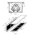
- the Fig. 2 shows a steel pipe assembly 15 according to the invention.
- Cable cores 10 are in plastic tubes 14, which are placed with a relatively large center distance from each other in the steel tube 15. Support element are not shown.
- a layer of shielding foils 20,22 surrounds the cable cores with a distance A2, wherein between Ablefolien 20,22 and the inner wall of the steel pipe 15, a different distance A1 is present.
- the distances A1, A2 are not essential to the invention, such as is still shown.
- the three inserted shielding foils 20,22 have gaps 17.
- the gap areas (with respect to the cylindrical enclosure of the power cable) may be between 5 and 30%, preferably 20%.
- the hollow or intermediate spaces 30 in the arrangement can be filled with a filler, preferably highly heat-conductive cement.
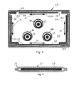
- the Fig. 3 shows further embodiments of the invention as ferromagnetic boxes 15 '. Rectangular shielding foils 20,22 are on both sides corrosion protected in the steel box 15 'introduced that they cover large areas of the bottom 50, the side walls 52 and the ceiling 54 of the steel box inside, ie on the cable 10 side facing.
- the high-permeability films 20 or sheets are made of special steel (my-metal, metallic glass) with a relative permeability of 40,000. This value is higher by a factor of 40 or more than normal steel.
- the function of the films is that the outer steel areas (50,52,54) are relieved of magnetic flux, so that while improving the shield factor of the arrangement, the losses in the steel, where it is covered by the sheets 20, significantly reduced become.
- the losses of the highly permeable material are almost negligible compared to steel. If it is a material with magnetic preferred direction (eg, a grain-oriented steel), so the films 20 are to be laid with their preferred magnetic direction M, as in the Fig. 3 shown azimuthal to the cables 10 and thus in the direction of the magnetic flux lines generated by the cables.
- the thickness of such shielding films 20 in many cases only needs to be a fraction of a millimeter in order to achieve, for example, the same shielding effect as a 10 mm thick steel wall.
- the shield factor increases and the losses in the steel box are reduced the more completely the steel surfaces are covered.
- the shielding foil is also inserted into the corners.
- the shielding film is recessed in the corners; There are gaps 17 between the adjacent foil parts 20,22 available.
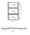
- FIGS. 4 . 5 and 6 show the structure of corrosion-protected shielding films 20.
- the shielding plates 20 are laid as individual panels or films with gaps behind each other and coated on both sides with two anti-corrosion films 21.
- In their overlapping areas 25, 27 (including the edges) they are welded or glued together on all sides or mechanically connected (stapled) (hereinafter also referred to as sandwich construction).
- This may be, for example, bitumen-coated strips or also strips with inserted vapor barrier, for example an aluminum foil.
- the Fig. 4 shows the sandwich construction in section of a both sides with a protective film 21 corrosion-protected shielding film 20th
- Fig. 5 It is shown how in the longitudinal direction behind each other along both sides laminated shielding films 22 are designed. Two slides in Fig. 5 are laid in the upper part of the figure with gap 27. In order to keep the gaps small, the shielding foils can of course also be designed to overlap (area 25), as in the lower area of the FIG. 5 shown.
- the principle of the band-shaped arrangement can also be implemented so that in a continuous manufacturing process on a running lower protective skin 21 at appropriate intervals shielding 20 can be placed to then accumulate an upper protective skin 21 and upper or lower protective skin both in the two outer overlapping areas (edge 23) and the overlapping areas 25 between the shielding to bond together to form an endless belt or welded.
- the band can subsequently be cut or separated in certain lengths.
- the combination with electrically highly conductive films is suitable for achieving even higher screen factors.
- the Fig. 7 shows a further possibility for wrapping cable wires 10 with Schirmungsfolie 20,22.
- the highly permeable Schirmungsfolie 20 is applied directly to the cable cores.
- a box after Fig. 7 can also be a steel pipe (see. Fig. 2 ) are used. It is based on an outer steel tube of correspondingly large diameter, in which usually three plastic tubes 14 are initially drawn for later receiving the cable cores 10. According to the proposal, these three plastic tubes 14 are first held at certain longitudinal intervals by means of moldings at the desired distance and wrapped in this position of the shielding film. The entire bandage is held by straps 18 to which spacers are also attached as skids (or with small rollers or wheels) for easy insertion into the tube and to ensure the desired spacing of the cables to the tube wall (such elements are already commercially available ).
- the Fig. 7 shows a steel box 15 'similar to in Fig. 3 ,
- the joints in the outer corners of the steel box are formed with flanges 55.
- a design with outwardly directed outer wall angles has the advantage that the inner walls of the steel box do not pop and so the shielding foils can be better designed or mounted.
- Fig. 8 is a schematic diagram reproduced as a steel box in the cable trench of individual elements A is constructed and composed of individual, already occupied with the shielding foil 22 areas (bottom 50, side walls 52, cover 54) and secured, for example, with screws 60 together.
- steel pipe constructions can be formed in individual elements of pipe sections (A).
- the construction after Fig. 8 - already referred to above with steel composite panel - is that on a steel plate (50, 52, 54) (which lies in the arrangement outside) - with a small gap or overlapping - placed the shielding and glued corrosion protected with the steel plate, or All round sealed (welded).
- the result is a composite plate, which can then be subjected to the usual in steel plates process of anti-corrosion preparation, such as galvanizing followed by coating (duplex protection), subjected.
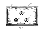
- the Fig. 9 shows a ferromagnetic box with inserted compensation conductors
- Three cable wires 10 of the power cable are placed with a relatively large center distance from one another in the form of a box 15 'shielding shell with walls in a rectangular arrangement.
- Two cable cores store in a first, lower laying level and the third cable core is laid in the middle above the two first cable cores.
- Two compensation conductors 12 are mounted in the first installation level directly next to the vertical side walls 52, and two compensation conductors 12 right and left above the third cable core directly below the box lid 54.
- the compensation conductors are preferably made of aluminum and are surrounded by a thin insulating sleeve for reasons of corrosion protection.
Landscapes
- Engineering & Computer Science (AREA)
- Architecture (AREA)
- Civil Engineering (AREA)
- Structural Engineering (AREA)
- Shielding Devices Or Components To Electric Or Magnetic Fields (AREA)
- Insulated Conductors (AREA)
- Laying Of Electric Cables Or Lines Outside (AREA)
Applications Claiming Priority (1)
| Application Number | Priority Date | Filing Date | Title |
|---|---|---|---|
| DE102009035064A DE102009035064A1 (de) | 2009-07-28 | 2009-07-28 | Hochwirksame, verlustarme ferromagnetische Verbundabschirmung |
Publications (3)
| Publication Number | Publication Date |
|---|---|
| EP2280462A2 true EP2280462A2 (fr) | 2011-02-02 |
| EP2280462A3 EP2280462A3 (fr) | 2014-07-09 |
| EP2280462B1 EP2280462B1 (fr) | 2017-08-30 |
Family
ID=43126896
Family Applications (1)
| Application Number | Title | Priority Date | Filing Date |
|---|---|---|---|
| EP10007720.5A Not-in-force EP2280462B1 (fr) | 2009-07-28 | 2010-07-26 | Ecran composite ferromagnétique hautement efficace et à faible usure |
Country Status (3)
| Country | Link |
|---|---|
| EP (1) | EP2280462B1 (fr) |
| DE (1) | DE102009035064A1 (fr) |
| DK (1) | DK2280462T3 (fr) |
Cited By (3)
| Publication number | Priority date | Publication date | Assignee | Title |
|---|---|---|---|---|
| WO2013053368A1 (fr) * | 2011-10-11 | 2013-04-18 | Prysmian S.P.A. | Canalisation électrique comprenant une goulotte passe-câbles à protection contre la corrosion et procédé permettant de protéger une goulotte passe-câbles contre la corrosion |
| WO2013072124A1 (fr) | 2011-11-14 | 2013-05-23 | Nv Bekaert Sa | Fil d'acier destiné à l'absorption de champs magnétiques |
| IT201600121212A1 (it) * | 2016-11-30 | 2018-05-30 | G Iron S R L | Canala portacavi schermante |
Families Citing this family (2)
| Publication number | Priority date | Publication date | Assignee | Title |
|---|---|---|---|---|
| DE102021205726A1 (de) | 2021-05-12 | 2022-11-17 | Volkswagen Aktiengesellschaft | Fahrzeug mit Hochstrom-Leitung |
| DE102024126057A1 (de) * | 2024-09-11 | 2026-03-12 | Rwe Offshore Wind Gmbh | Magnetfeldabschirmmatte, System mit einer Magnetfeldabschirmmatte sowie Verfahren zum Verlegen einer Magnetfeldabschirmmatte |
Citations (6)
| Publication number | Priority date | Publication date | Assignee | Title |
|---|---|---|---|---|
| DE19527974A1 (de) | 1995-07-24 | 1997-01-30 | Elektro Montage Nord Ing Rudol | Magnetische Abschirmung von elektrischen Anlagen |
| WO2004034539A1 (fr) | 2002-10-09 | 2004-04-22 | Pirelli & C. S.P.A. | Procede de criblage du champ magnetique genere par une ligne de transport d'electricite et ladite ligne de transport d'electricite ainsi criblee |
| WO2005013450A1 (fr) | 2003-07-30 | 2005-02-10 | Prysmian Cavi E Sistemi Energia S.R.L. | Procede de blindage du champ magnetique produit par une ligne electrique, et ligne electrique ainsi blindee |
| DE202006016804U1 (de) | 2005-11-04 | 2007-03-15 | Nkt Cables Gmbh | Kabelsystem mit magnetischer Schirmungshülle |
| US7241951B2 (en) | 2001-06-29 | 2007-07-10 | Pirelli & C. S.P.A. | Method for shielding the magnetic field generated by an electrical power transmission line, and magnetically shielded electrical power transmission line |
| DE102006013553B3 (de) | 2006-03-24 | 2007-10-18 | Nkt Cables Gmbh | Anordnung zum Umhüllen von mindestens einer Kabelader eines elektrischen Kabels |
Family Cites Families (5)
| Publication number | Priority date | Publication date | Assignee | Title |
|---|---|---|---|---|
| DE2446986C3 (de) * | 1974-10-02 | 1981-08-27 | Vacuumschmelze Gmbh, 6450 Hanau | Magnetische Abschirmvorrichtung |
| JPS6274445U (fr) * | 1985-10-30 | 1987-05-13 | ||
| DE19847123C2 (de) * | 1998-10-14 | 2001-07-19 | Felten & Guilleaume Kabelwerk | Erdverlegtes Energiekabel |
| DE60144372D1 (de) * | 2000-05-31 | 2011-05-19 | Prysmian Spa | Verfahren zum abschirmen des durch eine elektrische energieübertragungsleitung erzeugten magnetfeldes sowie elektrische energieübertragungsleitung |
| DE102007026648B3 (de) * | 2007-06-08 | 2008-10-16 | Nkt Cables Gmbh | Mechanische und thermische Verstärkung einer Kabelanordnung |
-
2009
- 2009-07-28 DE DE102009035064A patent/DE102009035064A1/de not_active Withdrawn
-
2010
- 2010-07-26 DK DK10007720.5T patent/DK2280462T3/en active
- 2010-07-26 EP EP10007720.5A patent/EP2280462B1/fr not_active Not-in-force
Patent Citations (6)
| Publication number | Priority date | Publication date | Assignee | Title |
|---|---|---|---|---|
| DE19527974A1 (de) | 1995-07-24 | 1997-01-30 | Elektro Montage Nord Ing Rudol | Magnetische Abschirmung von elektrischen Anlagen |
| US7241951B2 (en) | 2001-06-29 | 2007-07-10 | Pirelli & C. S.P.A. | Method for shielding the magnetic field generated by an electrical power transmission line, and magnetically shielded electrical power transmission line |
| WO2004034539A1 (fr) | 2002-10-09 | 2004-04-22 | Pirelli & C. S.P.A. | Procede de criblage du champ magnetique genere par une ligne de transport d'electricite et ladite ligne de transport d'electricite ainsi criblee |
| WO2005013450A1 (fr) | 2003-07-30 | 2005-02-10 | Prysmian Cavi E Sistemi Energia S.R.L. | Procede de blindage du champ magnetique produit par une ligne electrique, et ligne electrique ainsi blindee |
| DE202006016804U1 (de) | 2005-11-04 | 2007-03-15 | Nkt Cables Gmbh | Kabelsystem mit magnetischer Schirmungshülle |
| DE102006013553B3 (de) | 2006-03-24 | 2007-10-18 | Nkt Cables Gmbh | Anordnung zum Umhüllen von mindestens einer Kabelader eines elektrischen Kabels |
Cited By (7)
| Publication number | Priority date | Publication date | Assignee | Title |
|---|---|---|---|---|
| WO2013053368A1 (fr) * | 2011-10-11 | 2013-04-18 | Prysmian S.P.A. | Canalisation électrique comprenant une goulotte passe-câbles à protection contre la corrosion et procédé permettant de protéger une goulotte passe-câbles contre la corrosion |
| CN103975494A (zh) * | 2011-10-11 | 2014-08-06 | 普睿司曼股份公司 | 包括防腐蚀电线槽的输电线路和防护电线槽免被腐蚀的方法 |
| US9455558B2 (en) | 2011-10-11 | 2016-09-27 | Prysmian S.P.A | Electrical power transmission line comprising a corrosion-protected raceway and method of protecting a raceway from corrosion |
| AU2011379045B2 (en) * | 2011-10-11 | 2017-02-16 | Prysmian S.P.A. | Electrical power transmission line comprising a corrosion-protected raceway and method of protecting a raceway from corrosion |
| CN103975494B (zh) * | 2011-10-11 | 2017-07-21 | 普睿司曼股份公司 | 包括防腐蚀电线槽的输电线路和防护电线槽免被腐蚀的方法 |
| WO2013072124A1 (fr) | 2011-11-14 | 2013-05-23 | Nv Bekaert Sa | Fil d'acier destiné à l'absorption de champs magnétiques |
| IT201600121212A1 (it) * | 2016-11-30 | 2018-05-30 | G Iron S R L | Canala portacavi schermante |
Also Published As
| Publication number | Publication date |
|---|---|
| DK2280462T3 (en) | 2017-12-04 |
| EP2280462A3 (fr) | 2014-07-09 |
| DE102009035064A1 (de) | 2011-02-03 |
| EP2280462B1 (fr) | 2017-08-30 |
Similar Documents
| Publication | Publication Date | Title |
|---|---|---|
| EP2280462B1 (fr) | Ecran composite ferromagnétique hautement efficace et à faible usure | |
| EP3039759B1 (fr) | Traversée murale ignifuge pour un conducteur isolé électriquement et procédé de fabrication d'une traversée murale ignifuge | |
| EP3001435B1 (fr) | Noyau de transformateur à sec | |
| EP2287864B1 (fr) | Traversée tubulaire | |
| EP2661761B1 (fr) | Guide de conduites pour des transformateurs de transmission de courant continu haute tension et des bobines de réactance de transmission de courant continu haute tension | |
| EP1999832B1 (fr) | Dispositif pour envelopper au moins un fil d'un cable electrique | |
| EP2246948B1 (fr) | Agencement de compensation de champ magnétique dans des câbles à courant fort | |
| DE2710620C3 (de) | Schutzeinrichtung | |
| DE102007026648B3 (de) | Mechanische und thermische Verstärkung einer Kabelanordnung | |
| DE202007007507U1 (de) | Behälter zur Schirmung von Magnetfeldern niedriger Frequenz | |
| EP1783786B1 (fr) | Système de câble avec un écran magnétique | |
| DE102008060189A1 (de) | Blitzschutzummantelung für metallische Bauteile von Baukonstruktionen, wie Stützen oder Träger | |
| DE19847123C2 (de) | Erdverlegtes Energiekabel | |
| DE19527974C2 (de) | Magnetische Abschirmung von elektrischen Einrichtungen | |
| DE202006016804U1 (de) | Kabelsystem mit magnetischer Schirmungshülle | |
| DE2913055C2 (fr) | ||
| EP0380929B1 (fr) | Câble électrique de puissance | |
| DE1152734B (de) | Verfahren zur Herstellung einer Verankerung eines in einem Kabelkanal verlegten armierten Kabels in der Naehe einer Kabelverbindungsstelle | |
| DE202004012893U1 (de) | Einrichtung zur Abschirmung von Bauwerken und Teilen derselben, Wärmedämmverbundsystem sowie Bauwerk | |
| EP2020008A2 (fr) | Récipient de blindage contre les champs magnétiques à basse fréquence | |
| DE2523925B2 (de) | Strahlendes uhf-koaxialkabel | |
| DE2732652A1 (de) | Unterwasser-starkstromkabel mit einer leitenden abschirmung aus einem metallstreifen, der eine halbleitende schicht umgibt und mit dieser verklebt ist | |
| EP2259271A2 (fr) | Système triphasé haute tension et câble triphasé mono-conducteur doté d'un blindage pour le système | |
| DE3405079A1 (de) | Oelgefuelltes mehrkernkabel | |
| DE1488231C (de) | Verfahren zur Herstellung von elektrischen Abschirmungen und Leitbelägen |
Legal Events
| Date | Code | Title | Description |
|---|---|---|---|
| PUAI | Public reference made under article 153(3) epc to a published international application that has entered the european phase |
Free format text: ORIGINAL CODE: 0009012 |
|
| AK | Designated contracting states |
Kind code of ref document: A2 Designated state(s): AL AT BE BG CH CY CZ DE DK EE ES FI FR GB GR HR HU IE IS IT LI LT LU LV MC MK MT NL NO PL PT RO SE SI SK SM TR |
|
| AX | Request for extension of the european patent |
Extension state: BA ME RS |
|
| RAP1 | Party data changed (applicant data changed or rights of an application transferred) |
Owner name: NKT CABLES GMBH |
|
| RIC1 | Information provided on ipc code assigned before grant |
Ipc: H02G 3/04 20060101AFI20140403BHEP Ipc: H02G 9/04 20060101ALI20140403BHEP |
|
| PUAL | Search report despatched |
Free format text: ORIGINAL CODE: 0009013 |
|
| AK | Designated contracting states |
Kind code of ref document: A3 Designated state(s): AL AT BE BG CH CY CZ DE DK EE ES FI FR GB GR HR HU IE IS IT LI LT LU LV MC MK MT NL NO PL PT RO SE SI SK SM TR |
|
| AX | Request for extension of the european patent |
Extension state: BA ME RS |
|
| RIC1 | Information provided on ipc code assigned before grant |
Ipc: H02G 9/04 20060101ALI20140530BHEP Ipc: H02G 3/04 20060101AFI20140530BHEP |
|
| RAP1 | Party data changed (applicant data changed or rights of an application transferred) |
Owner name: NKT CABLES GMBH & CO. KG |
|
| 17P | Request for examination filed |
Effective date: 20150408 |
|
| RBV | Designated contracting states (corrected) |
Designated state(s): AL AT BE BG CH CY CZ DE DK EE ES FI FR GB GR HR HU IE IS IT LI LT LU LV MC MK MT NL NO PL PT RO SE SI SK SM TR |
|
| GRAP | Despatch of communication of intention to grant a patent |
Free format text: ORIGINAL CODE: EPIDOSNIGR1 |
|
| STAA | Information on the status of an ep patent application or granted ep patent |
Free format text: STATUS: GRANT OF PATENT IS INTENDED |
|
| INTG | Intention to grant announced |
Effective date: 20170316 |
|
| GRAS | Grant fee paid |
Free format text: ORIGINAL CODE: EPIDOSNIGR3 |
|
| GRAA | (expected) grant |
Free format text: ORIGINAL CODE: 0009210 |
|
| STAA | Information on the status of an ep patent application or granted ep patent |
Free format text: STATUS: THE PATENT HAS BEEN GRANTED |
|
| AK | Designated contracting states |
Kind code of ref document: B1 Designated state(s): AL AT BE BG CH CY CZ DE DK EE ES FI FR GB GR HR HU IE IS IT LI LT LU LV MC MK MT NL NO PL PT RO SE SI SK SM TR |
|
| REG | Reference to a national code |
Ref country code: GB Ref legal event code: FG4D Free format text: NOT ENGLISH |
|
| REG | Reference to a national code |
Ref country code: CH Ref legal event code: EP |
|
| REG | Reference to a national code |
Ref country code: AT Ref legal event code: REF Ref document number: 924482 Country of ref document: AT Kind code of ref document: T Effective date: 20170915 |
|
| REG | Reference to a national code |
Ref country code: IE Ref legal event code: FG4D Free format text: LANGUAGE OF EP DOCUMENT: GERMAN |
|
| REG | Reference to a national code |
Ref country code: DE Ref legal event code: R096 Ref document number: 502010014067 Country of ref document: DE |
|
| RAP2 | Party data changed (patent owner data changed or rights of a patent transferred) |
Owner name: NKT GMBH & CO. KG |
|
| REG | Reference to a national code |
Ref country code: BE Ref legal event code: HC Owner name: NKT GMBH & CO. KG; DE Free format text: DETAILS ASSIGNMENT: CHANGE OF OWNER(S), CHANGEMENT NOM PROPRIETAIRE; FORMER OWNER NAME: NKT CABLES GMBH & CO. KG Effective date: 20171116 |
|
| REG | Reference to a national code |
Ref country code: DK Ref legal event code: T3 Effective date: 20171127 |
|
| REG | Reference to a national code |
Ref country code: SE Ref legal event code: TRGR |
|
| REG | Reference to a national code |
Ref country code: CH Ref legal event code: PFA Owner name: NKT GMBH AND CO. KG, DE Free format text: FORMER OWNER: NKT CABLES GMBH AND CO. KG, DE |
|
| REG | Reference to a national code |
Ref country code: NL Ref legal event code: FP |
|
| REG | Reference to a national code |
Ref country code: LT Ref legal event code: MG4D |
|
| PG25 | Lapsed in a contracting state [announced via postgrant information from national office to epo] |
Ref country code: FI Free format text: LAPSE BECAUSE OF FAILURE TO SUBMIT A TRANSLATION OF THE DESCRIPTION OR TO PAY THE FEE WITHIN THE PRESCRIBED TIME-LIMIT Effective date: 20170830 Ref country code: NO Free format text: LAPSE BECAUSE OF FAILURE TO SUBMIT A TRANSLATION OF THE DESCRIPTION OR TO PAY THE FEE WITHIN THE PRESCRIBED TIME-LIMIT Effective date: 20171130 Ref country code: LT Free format text: LAPSE BECAUSE OF FAILURE TO SUBMIT A TRANSLATION OF THE DESCRIPTION OR TO PAY THE FEE WITHIN THE PRESCRIBED TIME-LIMIT Effective date: 20170830 Ref country code: HR Free format text: LAPSE BECAUSE OF FAILURE TO SUBMIT A TRANSLATION OF THE DESCRIPTION OR TO PAY THE FEE WITHIN THE PRESCRIBED TIME-LIMIT Effective date: 20170830 |
|
| REG | Reference to a national code |
Ref country code: AT Ref legal event code: HC Ref document number: 924482 Country of ref document: AT Kind code of ref document: T Owner name: NKT GMBH & CO. KG, DE Effective date: 20171219 |
|
| PG25 | Lapsed in a contracting state [announced via postgrant information from national office to epo] |
Ref country code: GR Free format text: LAPSE BECAUSE OF FAILURE TO SUBMIT A TRANSLATION OF THE DESCRIPTION OR TO PAY THE FEE WITHIN THE PRESCRIBED TIME-LIMIT Effective date: 20171201 Ref country code: ES Free format text: LAPSE BECAUSE OF FAILURE TO SUBMIT A TRANSLATION OF THE DESCRIPTION OR TO PAY THE FEE WITHIN THE PRESCRIBED TIME-LIMIT Effective date: 20170830 Ref country code: BG Free format text: LAPSE BECAUSE OF FAILURE TO SUBMIT A TRANSLATION OF THE DESCRIPTION OR TO PAY THE FEE WITHIN THE PRESCRIBED TIME-LIMIT Effective date: 20171130 Ref country code: LV Free format text: LAPSE BECAUSE OF FAILURE TO SUBMIT A TRANSLATION OF THE DESCRIPTION OR TO PAY THE FEE WITHIN THE PRESCRIBED TIME-LIMIT Effective date: 20170830 Ref country code: IS Free format text: LAPSE BECAUSE OF FAILURE TO SUBMIT A TRANSLATION OF THE DESCRIPTION OR TO PAY THE FEE WITHIN THE PRESCRIBED TIME-LIMIT Effective date: 20171230 |
|
| PG25 | Lapsed in a contracting state [announced via postgrant information from national office to epo] |
Ref country code: RO Free format text: LAPSE BECAUSE OF FAILURE TO SUBMIT A TRANSLATION OF THE DESCRIPTION OR TO PAY THE FEE WITHIN THE PRESCRIBED TIME-LIMIT Effective date: 20170830 Ref country code: PL Free format text: LAPSE BECAUSE OF FAILURE TO SUBMIT A TRANSLATION OF THE DESCRIPTION OR TO PAY THE FEE WITHIN THE PRESCRIBED TIME-LIMIT Effective date: 20170830 Ref country code: CZ Free format text: LAPSE BECAUSE OF FAILURE TO SUBMIT A TRANSLATION OF THE DESCRIPTION OR TO PAY THE FEE WITHIN THE PRESCRIBED TIME-LIMIT Effective date: 20170830 |
|
| PG25 | Lapsed in a contracting state [announced via postgrant information from national office to epo] |
Ref country code: SK Free format text: LAPSE BECAUSE OF FAILURE TO SUBMIT A TRANSLATION OF THE DESCRIPTION OR TO PAY THE FEE WITHIN THE PRESCRIBED TIME-LIMIT Effective date: 20170830 Ref country code: EE Free format text: LAPSE BECAUSE OF FAILURE TO SUBMIT A TRANSLATION OF THE DESCRIPTION OR TO PAY THE FEE WITHIN THE PRESCRIBED TIME-LIMIT Effective date: 20170830 Ref country code: SM Free format text: LAPSE BECAUSE OF FAILURE TO SUBMIT A TRANSLATION OF THE DESCRIPTION OR TO PAY THE FEE WITHIN THE PRESCRIBED TIME-LIMIT Effective date: 20170830 |
|
| REG | Reference to a national code |
Ref country code: DE Ref legal event code: R097 Ref document number: 502010014067 Country of ref document: DE |
|
| REG | Reference to a national code |
Ref country code: DE Ref legal event code: R082 Ref document number: 502010014067 Country of ref document: DE Representative=s name: FEDER WALTER EBERT PARTNERSCHAFT VON PATENTANW, DE Ref country code: DE Ref legal event code: R082 Ref document number: 502010014067 Country of ref document: DE Representative=s name: FEDER WALTER EBERT PATENTANWAELTE, DE Ref country code: DE Ref legal event code: R081 Ref document number: 502010014067 Country of ref document: DE Owner name: NKT GMBH & CO. KG, DE Free format text: FORMER OWNER: NKT CABLES GMBH & CO. KG, 51061 KOELN, DE |
|
| PLBE | No opposition filed within time limit |
Free format text: ORIGINAL CODE: 0009261 |
|
| STAA | Information on the status of an ep patent application or granted ep patent |
Free format text: STATUS: NO OPPOSITION FILED WITHIN TIME LIMIT |
|
| REG | Reference to a national code |
Ref country code: FR Ref legal event code: PLFP Year of fee payment: 9 |
|
| 26N | No opposition filed |
Effective date: 20180531 |
|
| PG25 | Lapsed in a contracting state [announced via postgrant information from national office to epo] |
Ref country code: SI Free format text: LAPSE BECAUSE OF FAILURE TO SUBMIT A TRANSLATION OF THE DESCRIPTION OR TO PAY THE FEE WITHIN THE PRESCRIBED TIME-LIMIT Effective date: 20170830 |
|
| PG25 | Lapsed in a contracting state [announced via postgrant information from national office to epo] |
Ref country code: MT Free format text: LAPSE BECAUSE OF FAILURE TO SUBMIT A TRANSLATION OF THE DESCRIPTION OR TO PAY THE FEE WITHIN THE PRESCRIBED TIME-LIMIT Effective date: 20170830 |
|
| PGFP | Annual fee paid to national office [announced via postgrant information from national office to epo] |
Ref country code: PL Payment date: 20180709 Year of fee payment: 9 |
|
| GBPC | Gb: european patent ceased through non-payment of renewal fee |
Effective date: 20180726 |
|
| PG25 | Lapsed in a contracting state [announced via postgrant information from national office to epo] |
Ref country code: MC Free format text: LAPSE BECAUSE OF FAILURE TO SUBMIT A TRANSLATION OF THE DESCRIPTION OR TO PAY THE FEE WITHIN THE PRESCRIBED TIME-LIMIT Effective date: 20170830 |
|
| REG | Reference to a national code |
Ref country code: IE Ref legal event code: MM4A |
|
| PG25 | Lapsed in a contracting state [announced via postgrant information from national office to epo] |
Ref country code: GB Free format text: LAPSE BECAUSE OF NON-PAYMENT OF DUE FEES Effective date: 20180726 Ref country code: IE Free format text: LAPSE BECAUSE OF NON-PAYMENT OF DUE FEES Effective date: 20180726 |
|
| REG | Reference to a national code |
Ref country code: AT Ref legal event code: MM01 Ref document number: 924482 Country of ref document: AT Kind code of ref document: T Effective date: 20190726 |
|
| PG25 | Lapsed in a contracting state [announced via postgrant information from national office to epo] |
Ref country code: TR Free format text: LAPSE BECAUSE OF FAILURE TO SUBMIT A TRANSLATION OF THE DESCRIPTION OR TO PAY THE FEE WITHIN THE PRESCRIBED TIME-LIMIT Effective date: 20170830 |
|
| PG25 | Lapsed in a contracting state [announced via postgrant information from national office to epo] |
Ref country code: AT Free format text: LAPSE BECAUSE OF NON-PAYMENT OF DUE FEES Effective date: 20190726 |
|
| PG25 | Lapsed in a contracting state [announced via postgrant information from national office to epo] |
Ref country code: HU Free format text: LAPSE BECAUSE OF FAILURE TO SUBMIT A TRANSLATION OF THE DESCRIPTION OR TO PAY THE FEE WITHIN THE PRESCRIBED TIME-LIMIT; INVALID AB INITIO Effective date: 20100726 Ref country code: PT Free format text: LAPSE BECAUSE OF FAILURE TO SUBMIT A TRANSLATION OF THE DESCRIPTION OR TO PAY THE FEE WITHIN THE PRESCRIBED TIME-LIMIT Effective date: 20170830 |
|
| PG25 | Lapsed in a contracting state [announced via postgrant information from national office to epo] |
Ref country code: MK Free format text: LAPSE BECAUSE OF NON-PAYMENT OF DUE FEES Effective date: 20170830 Ref country code: CY Free format text: LAPSE BECAUSE OF FAILURE TO SUBMIT A TRANSLATION OF THE DESCRIPTION OR TO PAY THE FEE WITHIN THE PRESCRIBED TIME-LIMIT Effective date: 20170830 |
|
| PG25 | Lapsed in a contracting state [announced via postgrant information from national office to epo] |
Ref country code: AL Free format text: LAPSE BECAUSE OF FAILURE TO SUBMIT A TRANSLATION OF THE DESCRIPTION OR TO PAY THE FEE WITHIN THE PRESCRIBED TIME-LIMIT Effective date: 20170830 |
|
| PGFP | Annual fee paid to national office [announced via postgrant information from national office to epo] |
Ref country code: NL Payment date: 20200717 Year of fee payment: 11 |
|
| PGFP | Annual fee paid to national office [announced via postgrant information from national office to epo] |
Ref country code: FR Payment date: 20200717 Year of fee payment: 11 Ref country code: DE Payment date: 20200721 Year of fee payment: 11 Ref country code: DK Payment date: 20200716 Year of fee payment: 11 Ref country code: LU Payment date: 20200717 Year of fee payment: 11 |
|
| PGFP | Annual fee paid to national office [announced via postgrant information from national office to epo] |
Ref country code: BE Payment date: 20200717 Year of fee payment: 11 Ref country code: SE Payment date: 20200716 Year of fee payment: 11 Ref country code: IT Payment date: 20200720 Year of fee payment: 11 Ref country code: CH Payment date: 20200710 Year of fee payment: 11 |
|
| REG | Reference to a national code |
Ref country code: DE Ref legal event code: R119 Ref document number: 502010014067 Country of ref document: DE |
|
| REG | Reference to a national code |
Ref country code: DK Ref legal event code: EBP Effective date: 20210731 |
|
| REG | Reference to a national code |
Ref country code: CH Ref legal event code: PL |
|
| REG | Reference to a national code |
Ref country code: NL Ref legal event code: MM Effective date: 20210801 |
|
| REG | Reference to a national code |
Ref country code: BE Ref legal event code: MM Effective date: 20210731 |
|
| PG25 | Lapsed in a contracting state [announced via postgrant information from national office to epo] |
Ref country code: LI Free format text: LAPSE BECAUSE OF NON-PAYMENT OF DUE FEES Effective date: 20210731 Ref country code: DE Free format text: LAPSE BECAUSE OF NON-PAYMENT OF DUE FEES Effective date: 20220201 Ref country code: CH Free format text: LAPSE BECAUSE OF NON-PAYMENT OF DUE FEES Effective date: 20210731 |
|
| PG25 | Lapsed in a contracting state [announced via postgrant information from national office to epo] |
Ref country code: SE Free format text: LAPSE BECAUSE OF NON-PAYMENT OF DUE FEES Effective date: 20210727 Ref country code: NL Free format text: LAPSE BECAUSE OF NON-PAYMENT OF DUE FEES Effective date: 20210801 Ref country code: LU Free format text: LAPSE BECAUSE OF NON-PAYMENT OF DUE FEES Effective date: 20210726 Ref country code: FR Free format text: LAPSE BECAUSE OF NON-PAYMENT OF DUE FEES Effective date: 20210731 |
|
| PG25 | Lapsed in a contracting state [announced via postgrant information from national office to epo] |
Ref country code: IT Free format text: LAPSE BECAUSE OF NON-PAYMENT OF DUE FEES Effective date: 20210726 Ref country code: DK Free format text: LAPSE BECAUSE OF NON-PAYMENT OF DUE FEES Effective date: 20210731 Ref country code: BE Free format text: LAPSE BECAUSE OF NON-PAYMENT OF DUE FEES Effective date: 20210731 |