EP2280595A2 - Enceinte submersible étanche - Google Patents
Enceinte submersible étanche Download PDFInfo
- Publication number
- EP2280595A2 EP2280595A2 EP10251347A EP10251347A EP2280595A2 EP 2280595 A2 EP2280595 A2 EP 2280595A2 EP 10251347 A EP10251347 A EP 10251347A EP 10251347 A EP10251347 A EP 10251347A EP 2280595 A2 EP2280595 A2 EP 2280595A2
- Authority
- EP
- European Patent Office
- Prior art keywords
- enclosure
- opening
- closure member
- electrical
- seal
- Prior art date
- Legal status (The legal status is an assumption and is not a legal conclusion. Google has not performed a legal analysis and makes no representation as to the accuracy of the status listed.)
- Withdrawn
Links
- XLYOFNOQVPJJNP-UHFFFAOYSA-N water Substances O XLYOFNOQVPJJNP-UHFFFAOYSA-N 0.000 title claims abstract description 20
- 230000000694 effects Effects 0.000 claims abstract description 9
- 239000007788 liquid Substances 0.000 claims abstract description 7
- 239000013536 elastomeric material Substances 0.000 claims description 5
- 230000013011 mating Effects 0.000 claims description 4
- 238000007789 sealing Methods 0.000 abstract description 10
- 230000015572 biosynthetic process Effects 0.000 description 6
- 238000005755 formation reaction Methods 0.000 description 6
- 230000002093 peripheral effect Effects 0.000 description 6
- 238000007654 immersion Methods 0.000 description 4
- 239000000428 dust Substances 0.000 description 2
- 238000004519 manufacturing process Methods 0.000 description 2
- 238000010276 construction Methods 0.000 description 1
- 230000002706 hydrostatic effect Effects 0.000 description 1
- 238000003780 insertion Methods 0.000 description 1
- 230000037431 insertion Effects 0.000 description 1
- 239000002184 metal Substances 0.000 description 1
- 239000002991 molded plastic Substances 0.000 description 1
- 239000004033 plastic Substances 0.000 description 1
- 229920003023 plastic Polymers 0.000 description 1
- 239000007787 solid Substances 0.000 description 1
- 238000005728 strengthening Methods 0.000 description 1
Images






Classifications
-
- H—ELECTRICITY
- H05—ELECTRIC TECHNIQUES NOT OTHERWISE PROVIDED FOR
- H05K—PRINTED CIRCUITS; CASINGS OR CONSTRUCTIONAL DETAILS OF ELECTRIC APPARATUS; MANUFACTURE OF ASSEMBLAGES OF ELECTRICAL COMPONENTS
- H05K5/00—Casings, cabinets or drawers for electric apparatus
- H05K5/06—Hermetically-sealed casings
- H05K5/061—Hermetically-sealed casings sealed by a gasket held between a removable cover and a body, e.g. O-ring, packing
Definitions
- the present invention relates to a watertight submersible enclosure and in particular concerns such an enclosure for sealingly enclosing electrical and/or electronic equipment or the like against the effects of submersion.
- Enclosures for electrical equipment can be classified according to an international classification system (EN60529) for the sealing effectiveness of enclosures against the intrusion into the electrical apparatus of foreign bodies such as tools, dust, fingers etc. and moisture.
- the classification system utilises the letters IP (Ingress Protection) followed by 2 or 3 digits.
- IP Ingress Protection
- the first digit of the IP code indicates the degree of protection provided for individuals against contact with moving parts (other than smooth rotating shafts, etc.) and the degree that the equipment is protected against the intrusion of solid foreign bodies into the enclosure. Zero represents the situation where the enclosure provides no special protection whereas 6 indicates that the enclosure is dust tight with the digits 1 to 5 representing intermediate conditions therebetween.
- the second digit indicates the degree of protection the enclosure provides for the enclosed electrical apparatus against the ingress of moisture into the enclosure.
- Zero indicates that the enclosure provides no special protection, 1 indicates protection from dripping water, 2 indicates protection from vertically dripping water, 3 indicates protection from sprayed water, 4 indicates protection from splashed water, 5 indicates protection from water projected from a nozzle, 6 indicates protection against heavy seas, or powerful jets of water, 7 indicates protection against immersion, and 8 indicates protection against complete and continuous submersion in water.
- These numbers are generally associated with a corresponding symbol which symbol are generally provided on the outer surface of an enclosure to indicate the IP protection provided by the enclosure.
- IP67 IP67 but not IP68.
- IP68 The requirement for protection against complete continuous submersion in water (IP68) is much more onerous than the requirement for an enclosure that can provide protection against immersion.
- Face seals are generally provided between the closure and a corresponding opening in a high performance enclosure, having say a classification of IP67, to provide an immersion resistant seal to prevent the ingress of moisture into the interior of the enclosure on immersion of the enclosure in water or other liquid. Hitherto manufacturers have been reluctant to classify electrical enclosures as IP68 because of the significantly higher performance requirements of an enclosure which is capable of remaining watertight on submersion.
- a water tight submersible enclosure for sealingly enclosing electrical/electronic apparatus or the like, said enclosure having at least one opening for access to the interior or a respective internal compartment of the enclosure and at least one respective closure member for closing the said opening, wherein a bore seal is provided at the said opening to seal the said opening against the effects of submersion of the enclosure in water or other liquid when the said respective closure member is attached to close the said opening and wherein at least one location means is provided at the said opening for positively locating the respective closure member on the said opening and the said location means comprises at least one upstanding element on one of the enclosure body or the closure member and a corresponding recess for receiving the said upstanding element on the other.
- the present inventors have found that significant improvements to sealing can be realised by using a bore seal type arrangement at the opening to be sealed by a respective closure member.
- This type of sealing arrangement it is possible to achieve a watertight seal which provides protection against the effects of submersion of the enclosure in water or other liquids.
- This type of sealing arrangement is therefore particularly suitable for applications in marine environments, for example, sealing electrical equipment that may, for example, be secured to a harbour wall or other maritime structure or vessel.
- the at least one location means is provided at or in the region of the opening or openings for positively locating the respective closure member on the opening.
- the above aspect of the present invention also contemplates embodiments where corresponding protrusion and grooves or overlapping lips are provided between the parts of the enclosure at the seated opening to reduce distortion of the enclosure body when subject to differential pressure acting on the enclosure in use or to reduce the distortion during manufacture if the enclosure is moulded. This is significantly important for relatively long straight or nearly straight parts which are moulded.
- the location means which in embodiments may also be used for reducing the effects of distortion as hereinbefore described, comprises at least one upstanding element on one of the enclosure bodies or the closure member and a corresponding recess for receiving the upstanding element on the other.
- the bore seal comprises a pair of mating elements, with one of the elements being provided on the closure member and the other around the periphery of the opening such that the elements are bought together when the closure member is attached to close the opening.
- the mating elements may comprise a female element and a male element with the bore seal further comprising a resilient seal element positioned between the male and female elements when the male and female elements are brought together to seal the opening. In this way sealing of the enclosure is further enhanced by the provision of the resilient seal element.
- the female element of the bore seal is provided by, or in the opening of the enclosure and the male element is provided as an upstanding protrusion on the closure member adapted to fit in the opening.
- This arrangement is particularly advantageous since it enables the resilient seal element to be accommodated in a recess provided either in the upstanding protrusion of the male element or around the periphery of the opening to be sealed as defined by the female element of the bore seal.
- the female element comprises a stepped recess at the opening, with the stepped recess being dimensioned to receive the male element.
- the resilient seal element preferably comprises a seal element of an elastomeric material.
- the seal element is preferably a loop of elastomeric material dimensioned to fit between the male and female elements of the bore seal.
- the seal element may be rubber or a synthetic elastomeric.
- the interior of the enclosure is divided to provide at least two internal compartments each having a respective opening and closure member.
- the enclosure is provided with a plurality of internal compartments, each of which is provided with a watertight bore seal. This may be important in applications where there is a requirement say to access electrical or electronic equipment in one of the compartments on a more regular basis than electrical or electronic apparatus in another compartment or compartments.
- respective adjacent closure members may be provided with respective overlapping parts which extend along a common adjoining edge such that one of the overlapping parts may be clamped by the other against the body of the enclosure when the adjacent closure members are secured to the body of the enclosure to close the respective openings of the adjacent internal compartments.
- fasteners such as fixing screws or the like to secure the respective closure members to the body of the enclosure.
- One of the internal compartments may be adapted to accommodate a power source such as a battery or the like for providing power, via an electrical connection, to electrical/electronic apparatus sealingly enclosed in one or more other internal compartments in the enclosure.
- a power source such as a battery or the like for providing power, via an electrical connection, to electrical/electronic apparatus sealingly enclosed in one or more other internal compartments in the enclosure.
- electrical terminal means are provided in a dividing wall between respective adjacent compartments for electrically connecting electrical/electronic apparatus and/or electrical power source means accommodated in adjacent compartments. In this way it is possible to electrically connect different apparatus located in different internal compartments within the enclosure.
- fixing means are provided for fixing a closure member to the body of the enclosure to close the respective opening.
- the fixing means comprise fasteners such as screws or the like which are capable of being tightened sufficiently to provide the watertight seal between the two parts of the enclosure.
- the enclosure comprises a pair of adjacent internal compartments, the respective openings of which are arranged either in a side-by-side relation on one side of the enclosure body or arranged at respective opposite ends of the enclosure.
- a water tight submersible enclosure for sealingly enclosing electrical/electronic apparatus or the like, said enclosure having at least one opening for access to the interior or a respective internal compartment of the enclosure and at least one respective closure member for closing the said opening, wherein a bore seal is provided at the said opening to seal the said opening against the effects of submersion of the enclosure in water or other liquid when the said respective closure member is attached to close the said opening.
- the at least one location means is provided at or in the region of the opening or openings for positively locating the respective closure member on the opening.
- the above aspect of the present invention also contemplates embodiments where corresponding protrusion and grooves or overlapping lips are provided between the parts of the enclosure at the sealed opening to reduce distortion of the enclosure body when subject to differential pressure acting on the enclosure in use or to reduce the distortion during manufacture if the enclosure is moulded. This is significantly important for relatively long straight or nearly straight parts which are moulded.
- the location means which may also be used for reducing the effects of distortion as hereinbefore described, may comprise at least one upstanding element on one of the enclosure bodies or the closure member and a corresponding recess for receiving the upstanding element on the other.
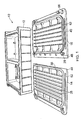
- FIG. 1 there is shown a first embodiment of a watertight submersible enclosure 10 for sealingly enclosing electrical/electronic apparatus or the like.
- the enclosure comprises three main components including a main body 12, a first closure member 14 and a second closure member 16.
- the component parts 12, 14 and 16 are preferably of moulded plastics construction, for example, moulded ABS, but the present invention contemplates other plastics and metal enclosures constructed in accordance with the illustrated design.
- the main body part of the enclosure comprises a generally rectangular structure having two adjacent internal compartments 18 and 20 disposed in side by side relation in the hollow interior region of the closure body 12.
- the internal compartments 18 and 20 are separated by an internal dividing wall 22 which extends perpendicularly from one side of the enclosure body 12 to the other to divide the hollow interior thereof into two open ended compartments 18 and 20 having substantially the same shape and dimensions.
- each of the internal compartments 18 and 20 is provided with a stepped recess 24 extending around its periphery.
- the stepped recess 24 constitutes one part of a bore seal for sealing the interior region of the compartments 18 and 20 when the respective closure members 14 and 16 are secured to the main body of the enclosure.
- a plurality of threaded inserts 26 are distributed around the outer periphery of the enclosure body 12 for receiving threaded fasteners 28 positioned in corresponding apertures around the periphery of the respective closure members 14 and 16. As shown in Figure 2 six such threaded inserts 26 are provided in the enclosure body, one at each corner of the enclosure body and one on each side at a mid point along the length of the enclosure body at a position corresponding to the position of the internal dividing wall 22.
- the longitudinal sides of the enclosure body 12 are provided with a plurality of equally spaced strengthening ribs 30 which extend outwards in a plane perpendicular to the longitudinal direction of the enclosure body 12, and which taper from a wide end in the region of the open top of the enclosure body to the base thereof.
- closure members 14 and 16 are shown with the underside of the respective members face up, the underside being defined as that face that faces the interior of the respective internal compartments 18 and 20 when fitted to the enclosure body to close the open internal compartments.
- each closure member 14 and 16 is provided with a plurality of upstanding surface formations, generally indicated 32, surrounded by an upstanding generally rectangular peripheral element 34 which has a shape and size corresponding to the recess 24 so that the upstanding element 34 fits in the recess 24 when the closure element is attached to the open top of the closure to close the respective internal compartment.
- the depth of the recess 24 is sufficient to accommodate the depth of the upstanding peripheral element 34 such that the two elements 24 cooperate to form a bore seal when the closure member is attached to the enclosure body as will be described in more detail below.
- the region on the underside of the closure members 14 and 16 bounded by the upstanding element 34 comprises a series of upstanding surface formations 32 in the form of a series of parallel longitudinal ribs 36 and perpendicular formations 38.
- the ribs 36 and formations 38 on the underside of the closure member 14 are different to those on the underside of the closure member 16, although it will appreciated that the peripheral upstanding element 34 is substantially the same on both.
- This difference in the shape and configuration of the ribs and formations 38 is a consequence of each internal compartment and its respective closure member being adapted to accommodate different electrical/electronic apparatus and/or power source apparatus such as a battery.
- the outward facing side of the peripheral upstanding element 34 is provided with a recess 40 for accommodating a resilient seal element 42 of an elastomeric material, preferably rubber.
- the seal element 42 protrudes out of the recess 40 so as to sealingly engage the recess 24 in the opening of a respective one of the internal compartment the closure member is associated with.
- the closure members 14 and 16 are provided with respective overlapping parts in the form of lip elements 44 and 46 which extend along the common adjoining edge of the closure members in such a way that when in the assembled configuration as shown in Figure 6 one of the overlapping parts 44 is clamped by the other 46 against the dividing wall of the enclosure body when the respective closure members 14 and 16 are fixedly secured to the enclosure body to close the respective openings of the respective adjacent internal compartments 18 and 20.
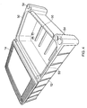
- This arrangement is illustrated in the sequential views of Figures 4 , 5 and 6 where Figure 4 shows the enclosure body 12 with the closure element 14 attached to close the internal compartment 20 with the adjacent compartment 18 open.
- Figure 5 shows the partly assembled enclosure of Figure 4 with the remaining closure member 16 positioned with its underside face down for attachment to the enclosure body to close the adjacent compartment 18 in such a way that the lip 46 sits on top of the corresponding lip 44 along the adjoining edge of the adjacent closure member.
- Figure 6 shows the closed enclosure with all six fixing screws 28 securely holding the closure members in clamping engagement with the enclosure body. In this configuration it will be understood that the clamping force provided by the fasteners 28 is sufficient to seal the enclosure against moisture ingress to provide a watertight seal for housing electrical/electronic apparatus and/or a power source, for such apparatus.
- one of the internal compartments may be adapted for receiving electrical/electronic apparatus and the other of the internal compartments for housing a battery or other power source with an electrical connection being provided by an appropriate terminal (not shown) in the interior dividing wall 22.
- the enclosure may be subject to significant pressure differentials during use due to hydrostatic and/or hydrodynamic pressure acting on the exterior of the enclosure with the interior being sealed at atmospheric pressure. Stiffening of the enclosure is provided by means of elongate upstanding surface formations 50, as best shown in Figure 4 , which extend along the edges of the enclosure around the respective openings.
- the upstanding projections 50 constitute one part of the additional stiffening, the other part being provided by corresponding recessed channels 52 in the underside of the respective closure members 14 and 16.
- each corner of the enclosure body is provided with a through bore 54, with corresponding through bores 56 in the respective corners of the closure members, for mounting the enclosure to an appropriate supporting structure such as a harbour wall or other maritime structure or vessel.
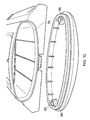
- the enclosure 60 comprises four main components including a main body part 62, a pair of closure members 64 and 66 for closing openings at opposite ends of the closure body 62 and a front cover plate 68 which also constitutes a closure member for closing and opening in the front of the closure member 62 as will be more fully described below.
- the enclosure 60 includes most of the features present in the first embodiment shown and described with reference to Figures 1 to 6 although the shape and configuration of the enclosure 60 is quite different.
- the enclosure 60 comprises an opening 70 at one end of the main body 62 and a second opening 72 at the opposite end thereof.
- the interior of the main body 62 between the respective openings 70 and 72 has a generally ovoid cross section in the plain perpendicular to the longitudinal direction of the enclosure.
- the closure members 64 and 66 are correspondingly shaped for closing the respective ends of the adjacent internal compartments 74 and 76 in the interior of the main body, which compartments 74 and 76 are divided by means of a dividing wall extending between the adjacent compartments in a plane substantially perpendicular to the longitudinal axis of the main body enclosure part 62.
- the dividing wall 78 functions in a similar way to the dividing wall 22 in the first embodiment and is provided with electrical terminals 80 for electrically connecting electrical/electronic apparatus in one of the compartments with a battery or other power source located in the other of the compartments.
- the open ends of the respective internal compartments constitute one part (female element) of a bore seal arrangement for sealingly enclosing the interior of the respective internal compartments when the respective closure members 64 and 66 are attached to the main body 62.
- the male part of the bore seal is provided by an upstanding peripheral element 82 on the underside of the respective closure members.
- the upstanding peripheral element is provided with a recess 84 on its outward facing surface for receiving a seal element 86 in the form of a loop of elastomeric material which is held under slight tension in the groove 84 of the closure members 64 and 66.
- the dimensions of the recessed groove 84 and the resilient sealing element 86 are such that the sealing element 86 is compressed between the groove 84 and the surface around the periphery of the respective opening to the internal compartment on insertion of the seal element into the respective opening.
- closure members 64 and 66 are fixably secured to the main body 62 by fastening means (not shown) positioned through bore apertures 88 in the closure members so that the closure members may be clamped tightly to the open end of the respective openings.
- a similar bore seal arrangement is provided on the underside of the front closure plate 68 so that an effective bore seal is created between the closure plate 68 and a correspondingly shaped recessed region 90 in the front face of the main enclosure body 62.
- the enclosure body is further provided with a mounting member 92 for attachment of the enclosure to a support structure.
- Apertures 92 are provided in scalloped regions at each of the four corners of the mounting member for receiving fixing screws or the like.
Landscapes
- Engineering & Computer Science (AREA)
- Microelectronics & Electronic Packaging (AREA)
- Casings For Electric Apparatus (AREA)
- Battery Mounting, Suspending (AREA)
Applications Claiming Priority (1)
| Application Number | Priority Date | Filing Date | Title |
|---|---|---|---|
| GBGB0913327.3A GB0913327D0 (en) | 2009-07-31 | 2009-07-31 | Water tight submersible enclosure |
Publications (2)
| Publication Number | Publication Date |
|---|---|
| EP2280595A2 true EP2280595A2 (fr) | 2011-02-02 |
| EP2280595A3 EP2280595A3 (fr) | 2011-05-18 |
Family
ID=41129394
Family Applications (1)
| Application Number | Title | Priority Date | Filing Date |
|---|---|---|---|
| EP10251347A Withdrawn EP2280595A3 (fr) | 2009-07-31 | 2010-07-29 | Enceinte submersible étanche |
Country Status (2)
| Country | Link |
|---|---|
| EP (1) | EP2280595A3 (fr) |
| GB (2) | GB0913327D0 (fr) |
Cited By (2)
| Publication number | Priority date | Publication date | Assignee | Title |
|---|---|---|---|---|
| CN102752983A (zh) * | 2012-07-12 | 2012-10-24 | 华为技术有限公司 | 地下柜设备 |
| CN107027251A (zh) * | 2016-01-29 | 2017-08-08 | 福特全球技术公司 | 车辆控制模块的保护罩 |
Family Cites Families (10)
| Publication number | Priority date | Publication date | Assignee | Title |
|---|---|---|---|---|
| FR1547693A (fr) * | 1967-10-18 | 1968-11-29 | Spirotechnique | Boitier étanche pour caméra sous-marine |
| US4295721A (en) * | 1980-04-23 | 1981-10-20 | Dimitri Rebikoff | High pressure and high speed optical enclosure system |
| JPH04217888A (ja) * | 1990-12-20 | 1992-08-07 | Nippon Otis Elevator Co | エレベータ制御のasr制御装置 |
| JPH0687951U (ja) * | 1993-05-24 | 1994-12-22 | 株式会社ニコン | 防水カメラ |
| TW337401U (en) * | 1997-10-09 | 1998-07-21 | Weltek Electronics Co Ltd | Waterproof case |
| GB9817277D0 (en) * | 1998-08-08 | 1998-10-07 | Bowes Edward M T | Modular housing construction and sealing means for use therewith |
| US6396769B1 (en) * | 1999-10-04 | 2002-05-28 | Rany Polany | System for housing a personal S.C.U.B.A diving audio system |
| CN2846988Y (zh) * | 2005-08-03 | 2006-12-13 | 深圳市海洋王投资发展有限公司 | 手提式防爆气体探照灯 |
| CN101008291B (zh) * | 2006-01-26 | 2010-05-12 | 金海产品有限公司 | 用于水池清洁机的密封盒装置 |
| US20080115772A1 (en) * | 2006-11-21 | 2008-05-22 | Ti Group Automotive Systems, L.L.C. | Fluid encapsulant for protecting electronics |
-
2009
- 2009-07-31 GB GBGB0913327.3A patent/GB0913327D0/en not_active Ceased
-
2010
- 2010-07-29 EP EP10251347A patent/EP2280595A3/fr not_active Withdrawn
- 2010-07-29 GB GB1012763A patent/GB2472320A/en not_active Withdrawn
Non-Patent Citations (1)
| Title |
|---|
| None |
Cited By (3)
| Publication number | Priority date | Publication date | Assignee | Title |
|---|---|---|---|---|
| CN102752983A (zh) * | 2012-07-12 | 2012-10-24 | 华为技术有限公司 | 地下柜设备 |
| WO2014008760A1 (fr) * | 2012-07-12 | 2014-01-16 | 华为技术有限公司 | Dispositif d'armoire souterrain |
| CN107027251A (zh) * | 2016-01-29 | 2017-08-08 | 福特全球技术公司 | 车辆控制模块的保护罩 |
Also Published As
| Publication number | Publication date |
|---|---|
| GB0913327D0 (en) | 2009-09-16 |
| GB2472320A (en) | 2011-02-02 |
| GB201012763D0 (en) | 2010-09-15 |
| EP2280595A3 (fr) | 2011-05-18 |
Similar Documents
| Publication | Publication Date | Title |
|---|---|---|
| EP2245713B1 (fr) | Cadre de transition à unité de compression intégrée | |
| JP7005119B2 (ja) | コネクタ | |
| EP1010215B1 (fr) | Connecteur electrique avec element d'etancheite commun | |
| US11596076B2 (en) | Sealing system for electronics enclosure | |
| JP5766029B2 (ja) | コネクタ | |
| WO2010011880A1 (fr) | Procédé et appareil permettant de fermer hermétiquement un boîtier | |
| EP2280595A2 (fr) | Enceinte submersible étanche | |
| US8570766B2 (en) | Shield case and communication device | |
| US20050115733A1 (en) | Compression unit | |
| US7484973B2 (en) | Weather-resistant electrical outlet cover | |
| US20030181087A1 (en) | Electrical connector | |
| US8050039B2 (en) | Portable environmentally robust enclosure optimized for size, weight, and power dissipation | |
| US9203223B2 (en) | Electrical connection box | |
| US6002083A (en) | Terminal box for electric motor | |
| CA2606637A1 (fr) | Convertisseur statique avec carter trempe protege contre les contraintes d'ambiance | |
| US11539091B2 (en) | Battery module | |
| GB2540600B (en) | An electrical component enclosure for recessing into and fixing to a surface | |
| GB2115614A (en) | Box for electrical components | |
| GB2424129A (en) | Cable gland having waterproof insert, sleave and clamping member | |
| US20030136574A1 (en) | Modular control casing | |
| JP7378896B2 (ja) | シール構造 | |
| CN223309306U (zh) | 光伏连接器及光伏连接器保护套 | |
| KR102592104B1 (ko) | 선박용 방수형 리셉터클 조립체 | |
| CN112576752A (zh) | 密封部件的密封布置,密封部件的密封表面的方法 | |
| CN217919276U (zh) | 密封盒及显示屏 |
Legal Events
| Date | Code | Title | Description |
|---|---|---|---|
| PUAI | Public reference made under article 153(3) epc to a published international application that has entered the european phase |
Free format text: ORIGINAL CODE: 0009012 |
|
| AK | Designated contracting states |
Kind code of ref document: A2 Designated state(s): AL AT BE BG CH CY CZ DE DK EE ES FI FR GB GR HR HU IE IS IT LI LT LU LV MC MK MT NL NO PL PT RO SE SI SK SM TR |
|
| AX | Request for extension of the european patent |
Extension state: BA ME RS |
|
| PUAL | Search report despatched |
Free format text: ORIGINAL CODE: 0009013 |
|
| AK | Designated contracting states |
Kind code of ref document: A3 Designated state(s): AL AT BE BG CH CY CZ DE DK EE ES FI FR GB GR HR HU IE IS IT LI LT LU LV MC MK MT NL NO PL PT RO SE SI SK SM TR |
|
| AX | Request for extension of the european patent |
Extension state: BA ME RS |
|
| STAA | Information on the status of an ep patent application or granted ep patent |
Free format text: STATUS: THE APPLICATION IS DEEMED TO BE WITHDRAWN |
|
| 18D | Application deemed to be withdrawn |
Effective date: 20111119 |