EP2281105B1 - Hybrides untersee-ventilaktuatorsystem und -verfahren - Google Patents
Hybrides untersee-ventilaktuatorsystem und -verfahren Download PDFInfo
- Publication number
- EP2281105B1 EP2281105B1 EP09746144.6A EP09746144A EP2281105B1 EP 2281105 B1 EP2281105 B1 EP 2281105B1 EP 09746144 A EP09746144 A EP 09746144A EP 2281105 B1 EP2281105 B1 EP 2281105B1
- Authority
- EP
- European Patent Office
- Prior art keywords
- cylinder
- piston
- hydraulic
- actuator
- motor
- Prior art date
- Legal status (The legal status is an assumption and is not a legal conclusion. Google has not performed a legal analysis and makes no representation as to the accuracy of the status listed.)
- Not-in-force
Links
Images


Classifications
-
- E—FIXED CONSTRUCTIONS
- E21—EARTH OR ROCK DRILLING; MINING
- E21B—EARTH OR ROCK DRILLING; OBTAINING OIL, GAS, WATER, SOLUBLE OR MELTABLE MATERIALS OR A SLURRY OF MINERALS FROM WELLS
- E21B33/00—Sealing or packing boreholes or wells
- E21B33/02—Surface sealing or packing
- E21B33/03—Well heads; Setting-up thereof
- E21B33/035—Well heads; Setting-up thereof specially adapted for underwater installations
- E21B33/0355—Control systems, e.g. hydraulic, pneumatic, electric, acoustic, for submerged well heads
-
- E—FIXED CONSTRUCTIONS
- E21—EARTH OR ROCK DRILLING; MINING
- E21B—EARTH OR ROCK DRILLING; OBTAINING OIL, GAS, WATER, SOLUBLE OR MELTABLE MATERIALS OR A SLURRY OF MINERALS FROM WELLS
- E21B34/00—Valve arrangements for boreholes or wells
- E21B34/02—Valve arrangements for boreholes or wells in well heads
- E21B34/04—Valve arrangements for boreholes or wells in well heads in underwater well heads
-
- Y—GENERAL TAGGING OF NEW TECHNOLOGICAL DEVELOPMENTS; GENERAL TAGGING OF CROSS-SECTIONAL TECHNOLOGIES SPANNING OVER SEVERAL SECTIONS OF THE IPC; TECHNICAL SUBJECTS COVERED BY FORMER USPC CROSS-REFERENCE ART COLLECTIONS [XRACs] AND DIGESTS
- Y10—TECHNICAL SUBJECTS COVERED BY FORMER USPC
- Y10T—TECHNICAL SUBJECTS COVERED BY FORMER US CLASSIFICATION
- Y10T137/00—Fluid handling
- Y10T137/0318—Processes
-
- Y—GENERAL TAGGING OF NEW TECHNOLOGICAL DEVELOPMENTS; GENERAL TAGGING OF CROSS-SECTIONAL TECHNOLOGIES SPANNING OVER SEVERAL SECTIONS OF THE IPC; TECHNICAL SUBJECTS COVERED BY FORMER USPC CROSS-REFERENCE ART COLLECTIONS [XRACs] AND DIGESTS
- Y10—TECHNICAL SUBJECTS COVERED BY FORMER USPC
- Y10T—TECHNICAL SUBJECTS COVERED BY FORMER US CLASSIFICATION
- Y10T137/00—Fluid handling
- Y10T137/0318—Processes
- Y10T137/0324—With control of flow by a condition or characteristic of a fluid
- Y10T137/0379—By fluid pressure
-
- Y—GENERAL TAGGING OF NEW TECHNOLOGICAL DEVELOPMENTS; GENERAL TAGGING OF CROSS-SECTIONAL TECHNOLOGIES SPANNING OVER SEVERAL SECTIONS OF THE IPC; TECHNICAL SUBJECTS COVERED BY FORMER USPC CROSS-REFERENCE ART COLLECTIONS [XRACs] AND DIGESTS
- Y10—TECHNICAL SUBJECTS COVERED BY FORMER USPC
- Y10T—TECHNICAL SUBJECTS COVERED BY FORMER US CLASSIFICATION
- Y10T137/00—Fluid handling
- Y10T137/0318—Processes
- Y10T137/0396—Involving pressure control
-
- Y—GENERAL TAGGING OF NEW TECHNOLOGICAL DEVELOPMENTS; GENERAL TAGGING OF CROSS-SECTIONAL TECHNOLOGIES SPANNING OVER SEVERAL SECTIONS OF THE IPC; TECHNICAL SUBJECTS COVERED BY FORMER USPC CROSS-REFERENCE ART COLLECTIONS [XRACs] AND DIGESTS
- Y10—TECHNICAL SUBJECTS COVERED BY FORMER USPC
- Y10T—TECHNICAL SUBJECTS COVERED BY FORMER US CLASSIFICATION
- Y10T137/00—Fluid handling
- Y10T137/7722—Line condition change responsive valves
- Y10T137/7723—Safety cut-off requiring reset
-
- Y—GENERAL TAGGING OF NEW TECHNOLOGICAL DEVELOPMENTS; GENERAL TAGGING OF CROSS-SECTIONAL TECHNOLOGIES SPANNING OVER SEVERAL SECTIONS OF THE IPC; TECHNICAL SUBJECTS COVERED BY FORMER USPC CROSS-REFERENCE ART COLLECTIONS [XRACs] AND DIGESTS
- Y10—TECHNICAL SUBJECTS COVERED BY FORMER USPC
- Y10T—TECHNICAL SUBJECTS COVERED BY FORMER US CLASSIFICATION
- Y10T137/00—Fluid handling
- Y10T137/8158—With indicator, register, recorder, alarm or inspection means
- Y10T137/8225—Position or extent of motion indicator
- Y10T137/8242—Electrical
Definitions
- the present invention relates generally to an actuator control system useful in sub sea production of hydrocarbons. It relates specifically to a sub sea valve actuator system and a method to achieve a simple and robust control system at low cost and low qualification effort.
- the actuator system is compatible with the concept of sub sea electric production control architecture.
- the prior art in control systems for hydrocarbon production comprises both hydraulic and electrical control, respectively.
- the present invention is based on a combination of principles pursued in both camps (roller screw and hydraulics) as per the above, and especially on the use only of the best components from each camp in a combination exhibiting unparalleled robustness and reliability combined with cost effectiveness.
- the critical feature of a sub sea valve actuator as applied to e.g. an XMT is in the fail safe latch arrangement. This is a mechanism designed to work in conjunction with a return spring, the latter storing energy required to turn the valve from the production position to the safer position, usually from open to closed position.
- the latch is usually also electromechanical.
- Many versions have been devised, but few implemented and commissioned in the sub sea industry.
- pressure relief valves sub sea has very little, if any, history in production control systems.
- the industry has shunned pressure regulating valves and pressure relief valves used sub sea.
- the full range of valves normally used in a mini SHPU dedicated to control of a single actuator are basically considered sensitive to particulate contamination and thus undesirable.
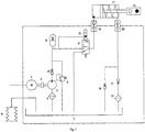
- Fig. 1 illustrates a typical prior art SHPU circuit pursued by several designers for achievement of an actuator using hydraulic components.
- the concept includes a pump driven by an electric motor, an accumulator for storage of hydraulic power, usually a filter for cleaning the fluid, and a solenoid operated DCV for directional control and a cylinder/piston unit.
- the latter is interfaced to the valve stem, providing the forces to bring the valve to the production position.
- a large return spring is usually provided for storage of the energy required to return the valve to the safe position when the hydraulic pressure is vented by the DCV when the solenoid is de-energized.
- a motor 1 connected to a pump 3 via a flexible coupling 2 to generate a pressure and a flow through check valve 13 such as to charge an accumulator 8.
- a pressure relief valve 5 is arranged as indicated in Fig. 1 for protection of the pump and motor.
- pilot valve 10 drives DCV 9 to the operating position to let fluid through connector 19 to actuator cylinder 11 and to drive a piston in cylinder 11 to the open position of the valve 12, also pushing fluid out from the spring side of the cylinder 11 through connector 20 and check valve 17 and filter 15.
- This circuit is suitable for a topside installation where the components most sensitive to contamination, notably DCV pilot valve 10 and pressure relief valve 5 may be accessed for repair or replacement, and where the ambient pressure at 1 bar is suitable for use of a nitrogen charged accumulator 8, but less suitable for a sub sea installation.
- the present invention aims for elimination of these three undesirable components, but still providing an operable actuation system of great robustness and reliability.
- GB 2 276 209 is concerned with an electrohydraulic valve actuator. It discloses a closest prior art sub sea valve actuator system comprising a piston and cylinder assembly and a return spring arranged in an actuator housing, a hydraulic pump and electric motor assembly associated with the piston and cylinder assembly and hydraulic flow lines for hydraulic medium driving the piston and cylinder in relative displacement against the force of the return spring.
- a linear variable differential transformer unit is arranged for detecting an end-of-stroke position of the piston and cylinder assembly, wherein an electromechanical arresting mechanism is arranged to be energized for releasably arresting the return spring in a compressed state in result of the detected end-of-stroke position.
- the subject actuator comprises a cylinder/piston assembly and a return spring arranged in an actuator housing as the main elements. Also in similarity with a conventional hydraulic actuator the move from production mode to safe mode is by action of the return spring, and the move from safe mode to production mode is provided by means of hydraulic power generated in the auxiliary circuitry forming an integral part of the actuator concept, but preferably located in a separately retrievable unit.
- the suggested circuit has no accumulator for storage of hydraulic power and no DCV pilot valve (or DCV). Nor has it a pressure relief valve. Thus the three least desirable components of the conventional concept have been eliminated.
- the motion of the piston/ cylinder follows simply as a function of fluid being pumped into the cylinder directly from the discharge port of the pump.
- the fail safe latch is an electromechanical arrangement (ref: electromechanical arresting mechanism).
- the arrangement comprises mechanical parts able to handle the reaction forces from the return spring and from the well bore pressure and is held in locked position by means only of a small electrical current and at a very low wattage. It is the introduction of this electro- mechanical fail safe arrangement which facilitates removal of the otherwise required components: accumulator (compensating for DCV leakage), DCV (essential function is to handle the ESD situation) and the pressure relief valve
- the fail safe latch arrangement only requires electrical power, no hydraulic power.
- the present invention also facilitates protection of motor and pump by detection of end-of stroke position.
- the present invention has characteristic performance very different from those of either an electromechanical actuator or an SHPU based actuator as described in the prior art references. It is truly an electric actuator as it has only electrical (and in the future possible optical) interfaces with the other parts of the production control system.
- the proposed design may be built for larger diameter and shorter length protruding from e.g. the trunk of an XMT, thus more compatible with sub sea XMT architectures.
- valve actuator system of the present invention can easily be expanded to serve fail-to-last position actuation, typically for a manifold or choke application, by simply reversing direction of rotation of the electrical motor, removing the fail safe spring and designing the piston/cylinder for bidirectional action.
- This assumes full reversibility of the pump, usually the case for a gear pump, not always the case for a piston pump.
- a motor as pump it would be beneficial to use a motor as pump as they are usually designed for true bidirectional operation both in pump and motor mode.
- the present invention provides a sub sea valve actuator system comprising a piston and cylinder assembly and a return spring arranged in an actuator housing, a hydraulic pump and electric motor assembly associated with the piston and cylinder assembly, hydraulic flow lines for hydraulic medium driving the piston and cylinder in relative displacement against the force of the return spring.
- the actuator system comprises detection means arranged for detecting an end-of-stroke position of the piston and cylinder assembly, said detection means is at least one of:
- At least one of the motor current monitoring circuit unit and the pressure sensor unit is contained in an electronics canister which is retrievably connected to the actuator housing.
- components of at least one of the position sensor unit and the linear variable differential transformer unit is contained in the actuator housing (i.e. the non-retrievable part of the actuator system).
- the motor current monitoring circuit unit is preferably arranged to submit an end-of-stroke signal to a logic unit controlling the electromechanical arresting mechanism to hold the valve in production mode against the force of the return spring.
- the pressure sensor unit is preferably arranged to generate a pressure signal in a logic unit controlling the electromechanical arresting mechanism to hold the valve in production mode against the force of the return spring.
- At least one of the position sensor unit and the linear variable differential transformer unit is preferably arranged to submit an end-of-stroke signal to a logic unit controlling the electromechanical arresting mechanism to hold the valve in production mode against the force of the return spring.
- the hydraulic pump and electrical motor assembly are assembled in a hydraulic power unit which is retrievably connected to the actuator housing.
- the hydraulic medium is preferably supplied to the piston/ cylinder assembly from a reversible, fixed displacement hydraulic pump.
- the actuator housing comprises a stem projecting from the cylinder in a forward direction, and a locking bolt projecting from the cylinder in the aft direction, the locking bolt reaching through the piston to be releasably engaged, in the end-of-stroke position of the cylinder, by locking dogs arranged pivotally in the actuator housing.
- the locking dogs are preferably controllable into locking engagement with the bolt upon energizing an electromagnet/solenoid or a shape memory alloy device.
- the present invention also provides a method for operation of a sub sea valve actuator system, comprising a piston and cylinder assembly and a return spring arranged in an actuator housing, a hydraulic pump and electric motor assembly associated with the piston and cylinder assembly, hydraulic flow lines for hydraulic medium driving the piston and cylinder in relative displacement against the force of the return spring.
- the method comprises the steps of:
- the prior art hydraulic circuit discussed in the background typically comprises the following components: an electric motor 1, flexible coupling 2, hydraulic pump 3, pump inlet strainer or filter 4, pressure relief valve 5, volume compensator 6, oil reservoir 7, hydraulic accumulator 8, control valve 9, pilot valve 10, hydraulic cylinder 11 with spring biased piston, gate valve 12, return filter 15, check valves 13, 17, 18 and hydraulic couplings 19 and 20.
- the motor 1 drives the pump 3 via flexible coupling 2 to create a pressure downstream the pump 3 as soon as the flow out of the pump is met with a restriction to flow.
- the least restriction to flow is represented by the small spring charged accumulator 14, organised to offer the motor a soft start at minimum torque, and thus allowing a fast acceleration of the motor rotor.
- the soft start is simply a piston type accumulator with a small spring, allowing fluid to be filled into the cylinder at low pressure until the cylinder is full and the piston is at end-of-travel.
- the fluid is forced through connector 19 into the cylinder 11 in order to push the piston in cylinder 11 against the return spring so as to push the gate 12 to the production position.
- Reference number 72 indicates the breakaway position
- 73 indicates the start of steady motion when the breakaway force is overcome.
- the motor is then switched off, and the actuator is held in position by means of the arresting mechanism which counteracts the entire force of the return spring of the cylinder 11.
- the arresting mechanism which counteracts the entire force of the return spring of the cylinder 11.
- Fig. 2 the structure and components of the sub sea valve actuator system will be described in more detail.
- the actuator components are contained in a housing comprised of a forward housing part 21 connected to an aft housing part 22.
- Reference number 23 refers to an ROV override facility
- reference number 24 refers to an actuator bonnet, which connects the gate valve actuator to the gate valve and provides an end wall of the housing part 21.
- a piston 25 and a cylinder 11 are arranged for relative displacement in the housing 21. More specifically, the cylinder 11 is arranged movable in both axial directions on a piston 25 which is stationary arranged in the housing. From a forward end wall of the cylinder 11, a stem 26 projects through the housing end wall or bonnet 24. The stem 26 provides a valve interface and is moveable linearly to effect shifting of the valve into production mode when the cylinder and stem are extended in the forward direction (i.e. towards the left hand side of the drawing). From the opposite side of the cylinder end wall, a locking bolt 27 projects into a bore 28 that is arranged centrally through the piston 25. The locking bolt 27 cooperates with an electromechanical locking or arresting mechanism as will be further explained with reference to Figs. 3 and 4 .
- the return spring 29 is releasably arrested in the compressed state through an electromechanical assembly comprising an electrically controlled trigger mechanism.
- the locking bolt 27 is arrested by engagement from a number of locking dogs 31 engaging a radial shoulder 32 that is formed on the locking bolt 27.
- the locking dogs 31 are preferably equidistantly spaced about the periphery of the locking bolt, and may be arranged at a number of two or more.
- the radial shoulder 32 connects an aft section of the locking bolt to a forward section 33 having greater diameter than the aft section.
- the locking dogs 31 are pivoted out of engagement with the radial shoulder 32, thus allowing the locking bolt 27, the cylinder 11 and the stem 26 to be driven in the aft direction by the expanding return spring 29.
- the locking dogs 31 are formed in a forward face with a circular or semicircular recess, and are journalled to slide pivotally on a circular or semicircular sliding surface 34 formed in the opposite face of the piston.
- the locking dogs 31 are further formed, in an aft face thereof, with a curved sliding surface abutting a stationary structure in the housing, here referred to as a locking dog interface structure 35, which provides a sliding surface on an axial counter-support for the locking dogs 31.
- the locking dogs 31 are formed with seats 36 in their peripheral ends.
- the seats 36 are shaped to receive, in the arrested state, a respective locking pin or locking ball 37 as illustrated in Fig. 3 .
- the locking pins 37 are pushed in radial direction into the seats 36 by actuation rods 38 having rounded ends, which are operated to move axially in the forward direction by means of an electromagnet/solenoid, or in the alternative by an SMA (shape memory alloy) device 39.
- SMA shape memory alloy
- the locking pins 37 are clamped between the locking dogs 31 and a radial shoulder 40 (see Fig. 4 ) formed on the actuator housing, this way positively preventing the locking dogs from pivoting about the slide surfaces 34 formed in the end of the piston 25.
- the solenoid or SMA device is de-energized, the actuation rods 38 are retracted in the aft direction, in the case of a solenoid by effect of a spring member (not shown).
- the locking pins 37 are then permitted to move in radial direction out from the seats 36, and are pushed by the pivoting locking dogs into recesses 41 ( Fig. 4 ) which are made accessible in the retracted position of the actuation rods 38.
- the piston/cylinder assembly 25/11 is powered by a hydraulic pump and electric motor assembly, see Figs. 2 and 5 .
- the pump 3 is of a fixed displacement reversible design which communicates hydraulic medium to the cylinder interior via a flow line 42 opening in the end of the piston 25, and to the actuator housing interior via flow line 43.
- the preferred embodiment shows a movable cylinder 11 and an annular piston 25 fixed in position where the stem is in the centre.
- a more general case (see Figs. 1 and 6 ) has a fixed cylinder and a movable piston.
- a preferred arrangement is an arrangement by which a stem connects all the way through to the ROV override facility. The practical adaptation is not critical for the invention, but is shown for completeness of description.
- Fig. 5 illustrates a slightly modified modularisation of the actuator system shown in Fig. 2 with respect to the horizontal versus vertical orientation of the hydraulic power unit.
- the purpose of this embodiment is to reduce the diameter of the actuator design, protruding from e.g. an XMT trunk, to make it more compatible with XMT topology and space constraints.
- This embodiment may beneficially employ individual hydraulic stab connectors rather than the flange connection shown in Fig. 2 .
- a sub-sea hydraulic power unit SHPU is housed in a separate and retrievable SHPU-module comprising the motor and pump assembly encased in a housing 44.
- Reference number 45 refers to a protection cap for a metal bellows volume compensator 6, compensating for volume changes of the fluid in the actuator as a result of changes in pressure and temperature. Such devices are commonplace components in the sub sea industry and the component is shown for completeness of description.
- the SHPU connects to the actuator housing 21 via a connecting flange 47 and clamp interface 48.
- Reference numbers 49 and 50 refer to bearing arrangements journaling a rotor 51 for rotation relative to a stator 52.
- Electrical power and control is supplied from a host facility via lines connected to the gate valve actuator at wet mate connector 53.
- a supplementary connector 54 may advantageously be arranged for back up in a case where connector 53 is disconnected upon retrieval of the SHPU.
- Reference number 55 refers to a separately retrievable electronics canister housing the electric/electronics components necessary for
- the motor 1 can be designed in many forms.
- a squirrel cage motor with the rotor 51 designed for very high resistance in the rotor bars is used.
- the bars could be made of a less conductive material than copper as opposed to the normal design of using copper, or the entire rotor can be a solid cylindrical piece of magnetic steel (in the latter case it is then strictly speaking not a squirrel cage anymore). This makes it possible for a motor of low efficiency when running at rated speed, but also for a motor of very low inrush current, high starting torque and very tolerant to heating.
- efficiency of the motor running at rated speed is not a major issue, however, inrush current is a major issue in view of the long transmission lines used in sub sea field developments.
- Direct starting of the motor by means of conventional electromechanical contactors makes it possible for a robust scheme using simple equipment, but for a standard industrial induction motor of the squirrel cage design this tends to create large voltage drop on the transmission lines in response to large inrush currents and low load angle values at start-up.
- the motor only runs for 30-60 seconds per actuation, so the aggregated power loss in the form of heat is insignificant.
- the motor stator 52 is wound for very low voltages, typically 40-60 volts for a 5 kW unit (typical rating for a 5" actuator).
- the entire housing containing the motor/pump and auxiliary valves is filled with a suitable mineral oil based or synthetic hydraulic fluid. All such fluids have excellent electrical insulation characteristics at low voltages, even when absorbing sea water.
- the hydraulic fluid is thus optimised on lubrication for the motor and pump bearings and performance of the pump in addition to corrosion resistance of the wetted components.
- gear pumps have inherently an internal leakage, normally considered a disadvantage, in this context however considered an advantage, as the actuator is certain to go to the valve safe position even if the pump or motor were to freeze up on their respective bearings. In this unlikely case the shut in time would increase, but shut-in would eventually happen.
- the pump 3 is in the preferred embodiment of a gear type design for robustness and cost effectiveness, but could also be of an axial piston type design or some other form of fixed displacement machine.
- the basic requirement is that the pumping action is reversible such that the pump is run as a motor under the pressure generated by the return spring 29 in cylinder 11 when the motor 1 is de-energised and the locking dogs 31 are released for shut-in.
- the hydraulic circuit has intentionally no capability to hold the stem 26 in the extended position at pump standstill. Once the motor is de-energized and the locking dogs 31 are released, the return spring 29 will drive the stem assembly to the safe position of the valve.
- Only the mechanical fail safe mechanism (ref: electromechanical arresting mechanism) shown in Figs. 3 and 4 is intended to hold the valve in the production mode.
- the electric motor and hydraulic circuitry only constitute the simple function of a jack device.
- the check valves 17 and 18 are of non-critical nature. They are put in to make sure the fluid which alternately runs in and out of the cylinder spring side is passed through the filter 15 (typically a 3 micron unit), as springs are known to contaminate the fluid.
- the most common failure mode of a check valve is leakage when subject to pressure in the blocking direction.
- the check valves are not subject to pressure of significance. Minor leakages are of no consequence, as they will only result in a marginal reduction of the fluid filtration process.
- adding another two, non-critical check valves to this circuit results in also the fluid being sucked into the spring side of the piston being filtered (rectifier circuit).
- a similar arrangement may be made for the suction side of the pump (not shown).
- the hydraulic circuit shown in Fig. 6 , is very robust with respect to particulate contamination which is usually considered the main source of failure in hydraulic systems.
- seals 63 are also arranged in the interface between the cylinder 11 and piston 25 to separate the cylinder interior from the oil-filled interior 64 of the actuator housing 21.
- Fig. 7 shows the development of hydraulic pressure in the actuator cylinder and Fig. 8 shows the corresponding motor stator currents, respectively, as a function of time for a typical actuation stroke sequence.
- the motor When the motor is started it drives the pump against a low pressure 71 schematically represented by the spring force in the soft starter piston 14 (hydraulic accumulator 14 of piston type) (see Fig. 6 ).
- the soft starter piston When the soft starter piston reaches end-of-travel (motor at full speed) the full breakaway force of the valve 12 is applied and the pressure increases from 71 to 72.
- the pressure is then immediately reduced as the piston 25 in the cylinder 11 starts to move against the force of the return spring 29 at 73.
- reference number 80 indicates the starting point where the power is applied to the motor, and 81 is the point where the inrush current of the motor reaches its maximum value.
- Reference number 82 is the steady state at full motor speed, no-load value of the motor current, and 83 is the point where the soft start accumulator 14 hits end-of-stroke.
- Reference number 84 is the point where the breakaway force of the valve 12 is overcome, and 85 is the start of the stroke in steady motion.
- Reference number 86 indicates the end-of-stroke where the pump/rotor is decelerated to stalling (or very near stalling), and 87 is the point where the current supplied to the stator windings of the stalling motor.
- reference number 88 indicates the point where the locking dogs 31 have been activated and the motor power is switched off upon passage of a certain delay in time during which the motor 1 is stalled at full torque
- Fig. 9 schematically shows the electrical circuitry of an actuator control system according to a preferred embodiment of the present invention.
- Power is supplied from host facility via transformer unit 91.
- a motor current transformer 94 works with interface circuitry (not shown) to read back to a programmable logic controller unit (PLC unit) 95 the value of one or more electrical phase currents in the electrical motor.
- PLC unit programmable logic controller unit
- the PLC 95 is equipped with a normal serial communications line 96 and digital I/O control line 93 driving relays 92, 92'.
- the PLC unit receives a command from the topside installation via the various legs of the sub sea communication system (line 96) and pulls primary relay 92 to start the motor 1.
- the secondary relay 92' is installed for correction of the phase sequence and is in principle superfluous for an installation where correct wiring throughout is secured. Some operators may not accept dependence on such critical wiring. If the pump does not create a pressure when running this is indicative of erroneous phase connection. The secondary relay 92' may then be activated.
- Fig. 10 suggests alternative sensor instrumentation in other preferred embodiments of the present invention. This instrumentation may also be additional to improve the detection of end-of-stroke position with the primary inferential method described above, i.e. stator current detection through motor current transformer unit 94.
- a pressure sensor/transducer unit 98 is fitted at a place where the hydraulic pressure in the actuator is to be measured, e.g. to the pump outlet port tubing 42 ( Fig. 2 ) (flowline for hydraulic medium) of the pump to detect at all times the pressure in the hydraulic fluid driving the piston/cylinder displacement.
- This pressure sensor unit will detect a pressure over time during an actuator stroke as shown in Fig. 7 .
- this sensor unit will indicate end-of-stroke position of the piston/cylinder assembly and additionally provide inferential readings of valve position.
- Fig. 10 also suggests a position sensor unit 99, intended for detection of end-of-stroke position of the piston/cylinder.
- This position sensor unit could be used as an alternative to the other types of sensor instrumentation or be combined with any of the sensor instrumentation for further improving the confidence in detection.
- a position sensor unit 99 of inductive type is a very simple instrument comprising a coil of wire, excitation circuit and a detector.
- the electronic circuit of the inductive position sensor unit 99 is embedded in the electronics canister 55 (see Fig. 2 ) and the coil of wire is preferably embedded in the non-movable part of piston/cylinder assembly, though not illustrated in the figures.
- a second position sensor unit of another type, typically magnetic or optical, could be installed to confirm end-of-stroke position or could be installed instead of a position sensor unit 99 of inductive type.
- position sensors are suitable in a sub sea environment.
- LVDT unit linear variable differential transformer unit
- the electronic circuit of LVDT unit is embedded in the electronics canister 55 (see Fig. 2 ) and the coils of wire are preferably embedded in the non-movable part of piston/cylinder assembly 11, though not illustrated in the figures.
- Both the pressure senor unit 98 and the motor current monitoring circuit unit or motor current transformer unit 94 described above are located in a module or electronics canister 55 which is easily retrievable for maintenance or replacement by means of e.g. simple and proven ROV operations.
- Components relating to the position sensor 99 and the LVDT unit 100 have to be embedded in the non-retrievable part 21 of the valve actuator system.
- the preferred embodiments based on inferential detection of end-of-stroke position i.e. motor current monitoring by means of a current transformer unit 94 or pressure sensing by means of a pressure sensor unit 98, requires only one ROV operated electrical connector 53 between the electronics canister 55 and the upstream power supply and communications centre (not shown). If either an LVDT unit or an inductive position sensor according to other preferred embodiments are implemented, then an additional ROV operated electrical connector 54 connecting electrical components in the cylinder part of the actuator with the electronic circuitry in the electronics canister 55 would be required. This represents additional cost and mechanical complexity, but represents well proven components and operations.
Landscapes
- Life Sciences & Earth Sciences (AREA)
- Engineering & Computer Science (AREA)
- Geology (AREA)
- Mining & Mineral Resources (AREA)
- Physics & Mathematics (AREA)
- Environmental & Geological Engineering (AREA)
- Fluid Mechanics (AREA)
- General Life Sciences & Earth Sciences (AREA)
- Geochemistry & Mineralogy (AREA)
- Fluid-Pressure Circuits (AREA)
- Actuator (AREA)
Claims (17)
- Unterwasserventil (12)-Stellgliedsystem, umfassend eine Kolben (25)- und Zylinder (11)-Anordnung und eine in einem Stellgliedgehäuse (21, 22) angeordnete Rückstellfeder (29), eine Hydraulikpumpe (3)- und Elektromotor (1)-Anordnung (1), die der Kolben (25)- und Zylinder (11)-Anordnung zugeordnet ist, hydraulische Strömungsleitungen (42, 43) für hydraulisches Medium, das den Kolben und Zylinder in relativer Verschiebung gegen die Kraft der Rückstellfeder (29) antreibt,
wobei ein Erfassungsmittel zum Erfassen einer Endhubposition der Kolben (25)-und Zylinder (11)-Anordnung angeordnet ist,
wobei das Erfassungsmittel mindestens eines ist von:- einer Motorstromüberwachungsschaltungseinheit (94);- einer Hydraulikmedium-Drucksensoreinheit (98);- einer Positionssensoreinheit (99); und- einer linear variablen Differentialtransformatoreinheit (100),wobei ein elektromechanischer Arretiermechanismus angeordnet ist, um erregt zu werden, um die Rückstellfeder in einem komprimierten Zustand als Ergebnis der erfassten Endhubposition lösbar zu arretieren,
wobei hydraulisches Medium über eine Strömungsleitung (42)-Öffnung im Ende des Kolbens (25) zugeführt wird, der feststehend im Stellgliedgehäuse (21, 22) ist, und der Zylinder (11) verschiebbar auf dem Kolben (25) im Stellgliedgehäuse (21) angeordnet ist, das mit hydraulischen Medium gefüllt, das mit der hydraulischen Pumpe (3) über eine Rückströmungsleitung (43) kommuniziert. - Stellgliedsystem nach Anspruch 1, wobei das Erfassungsmittel eine Motorstromüberwachungsschaltungseinheit (94) und/oder eine Drucksensoreinheit (98) ist, die in einem Elektronikbehälter (55) enthalten sind, der mit dem Stellgliedgehäuse (21, 22) lösbar verbunden ist.
- Stellgliedsystem nach Anspruch 1, wobei das Erfassungsmittel eine Positionssensoreinheit (99) und/oder eine linear variable Differentialtransformatoreinheit (100) ist, die im Stellgliedgehäuse (21, 22) enthalten sind.
- Stellgliedsystem nach einem der Ansprüche 1 bis 3, wobei das Erfassungsmittel eine Motorstromüberwachungsschaltungseinheit (94) ist, die angeordnet ist, um ein Endhubsignal an eine Logikeinheit (PLC) zu senden, die den elektromechanischen Arretiermechanismus steuert, um das Ventil im Produktionsmodus gegen die Kraft der Rückstellfeder zu halten.
- Stellgliedsystem nach einem der Ansprüche 1 bis 3, wobei das Erfassungsmittel eine Drucksensoreinheit (98) ist, die angeordnet ist, um ein Drucksignal in einer Logikeinheit (PLC) zu erzeugen, die den elektromechanischen Arretiermechanismus steuert, um das Ventil im Produktionsmodus gegen die Kraft der Rückstellfeder zu halten.
- Stellgliedsystem nach einem der Ansprüche 1 bis 3, wobei das Erfassungsmittel eine Positionssensoreinheit (99) und/oder eine linear variable Differentialtransformatoreinheit (100) ist, die angeordnet sind, um ein Endhubsignal an eine Logikeinheit (PLC) zu senden, die den elektromechanischen Arretiermechanismus steuert, um das Ventil im Produktionsmodus gegen die Kraft der Rückstellfeder zu halten.
- Stellgliedsystem nach einem der Ansprüche 1 bis 6, dadurch gekennzeichnet, dass die Hydraulikpumpe (3)- und Elektromotor (1)-Anordnung in einem Hydraulikaggregat montiert sind, das mit dem Stellgliedgehäuse (21, 22) lösbar verbunden ist.
- Stellgliedsystem nach Anspruch 7, dadurch gekennzeichnet, dass Hydraulikmedium der Kolben/Zylinder-Anordnung von einer reversiblen, fest eingestellten Hydraulikpumpe (3) zugeführt wird.
- Stellgliedsystem nach einem der vorherigen Ansprüche, dadurch gekennzeichnet, dass das Stellgliedgehäuse eine Stange (26), die vom Zylinder (11) in Vorwärtsrichtung vorsteht, und einen Verriegelungsbolzen (27), der vom Zylinder (11) in Heckrichtung vorsteht, umfasst, der Verriegelungsbolzen durch den Kolben (25) reicht, um in der Endhubposition des Zylinders (11) durch schwenkbar im Stellgliedgehäuse (21, 22) angeordnete Verriegelungsnocken (31) lösbar in Eingriff zu kommen.
- Stellgliedsystem nach Anspruch 9, dadurch gekennzeichnet, dass die Verriegelungsnocken (31) beim Erregen eines Elektromagneten/einer Magnetspule (97) oder einer Formgedächtnislegierungsvorrichtung (39) in Verriegelungseingriff mit dem Bolzen (27) steuerbar sind.
- Verfahren zum Betreiben eines Unterwasserventil-Stellgliedsystems, umfassend eine Kolben (25)- und Zylinder (11)-Anordnung und eine in einem Stellgliedgehäuse (21, 22) angeordnete Rückstellfeder (29), eine Hydraulikpumpe (3)- und Elektromotor (1)-Anordnung, die der Kolben (25)- und Zylinder (11)-Anordnung zugeordnet ist, hydraulische Strömungsleitungen (42, 43) für ein hydraulisches Medium, das den Kolben und Zylinder in relativer Verschiebung gegen die Kraft der Rückstellfeder (29) antreibt, wobei das Verfahren die folgenden Schritte umfasst:- Anordnen eines elektromechanischen Arretiermechanismus, der wirksam ist, um die Rückstellfeder in einem komprimierten Zustand lösbar zu arretieren;- Bestimmen einer Endhubposition der Kolben (25)- und Zylinder (11)-Anordnung durch mindestens eines von:- Erfassen des Stroms, der dem Elektromotor zugeführt/von ihm verbraucht wird;- Erfassen des Drucks im hydraulischen Medium;- Erfassen der Position des Kolbens relativ zum Zylinder; und- Erfassen der absoluten Position des Kolbens oder des Zylinders; und- Erregen des elektromechanischen Arretiermechanismus als Ergebnis der erfassten Endhubposition der Kolben- (25) und Zylinder (11)-Anordnung;- Zuführen eines hydraulischen Mediums über eine Strömungsleitung-Öffnung im Ende des Kolbens, der feststehend im Stellgliedgehäuse ist;- verschiebliches Anordnen des Zylinders auf dem Kolben im Stellgliedgehäuse, das mit hydraulischem Medium gefüllt ist, das mit der Hydraulikpumpe über eine Rückströmungsleitung kommuniziert.
- Verfahren nach Anspruch 11, gekennzeichnet durch den Schritt des Antreibens des Motors (1) im Stillstand in der Endhubposition, während mindestens einer der Motorstromaufnahme, des hydraulischen Mitteldrucks, der Position des Kolbens in Bezug auf den Zylinder und der absoluten Position des Kolbens oder des Zylinders erfasst wird, und des Abbruchs der Stromversorgung des Motors nach dem Erfassen der Endhubposition der Kolben/Zylinder-Anordnung.
- Verfahren nach Anspruch 12, gekennzeichnet durch den Schritt des Aktivierens des elektromechanischen Arretiermechanismus nach Ablauf einer bestimmten Zeitverzögerung, während der der Motor (1) bei vollem Drehmoment blockiert wird.
- Verfahren nach einem der Ansprüche 12 bis 13, gekennzeichnet durch den Schritt des Beschleunigens des Motors bei minimalem Drehmoment, das von einem federbelasteten Speicher (14) bereitgestellt wird, der im Strom des hydraulischen Mediums von der Pumpe (3) zum Zylinder (11) angeordnet ist.
- Verfahren nach einem der Ansprüche 11-14, gekennzeichnet durch den Schritt des Anordnens von mindestens einer Motorstromüberwachungsschaltungseinheit (94) und einer Hydraulikmedium-Drucksensoreinheit (99) in einem separaten lösbaren Elektronikbehälter (55), der mit dem Stellgliedgehäuse (21, 22) verbindbar ist.
- Verfahren nach einem der Ansprüche 11-15, gekennzeichnet durch den Schritt des Anordnens von Komponenten mindestens einer von einer Positionssensoreinheit (99) und einer linear variablen Differentialtransformatoreinheit (100) im Stellgliedgehäuse (21, 22).
- Verfahren nach einem der Ansprüche 11 bis 16, gekennzeichnet durch den Schritt des Zusammenbaus der Hydraulikpumpe (3) und des Elektromotors (1) in einem Hydraulikaggregat, das mit dem Stellgliedgehäuse (21, 22) lösbar verbunden ist.
Priority Applications (1)
| Application Number | Priority Date | Filing Date | Title |
|---|---|---|---|
| PL09746144T PL2281105T3 (pl) | 2008-05-14 | 2009-05-12 | Podmorski system siłownika zaworu hybrydowego oraz sposób |
Applications Claiming Priority (2)
| Application Number | Priority Date | Filing Date | Title |
|---|---|---|---|
| NO20082217A NO328603B1 (no) | 2008-05-14 | 2008-05-14 | Undervanns hybrid ventilaktuatorsystem og fremgangsmate. |
| PCT/IB2009/005567 WO2009138849A1 (en) | 2008-05-14 | 2009-05-12 | A sub sea hybrid valve actuator system and method |
Publications (3)
| Publication Number | Publication Date |
|---|---|
| EP2281105A1 EP2281105A1 (de) | 2011-02-09 |
| EP2281105A4 EP2281105A4 (de) | 2016-04-06 |
| EP2281105B1 true EP2281105B1 (de) | 2018-12-12 |
Family
ID=41318399
Family Applications (1)
| Application Number | Title | Priority Date | Filing Date |
|---|---|---|---|
| EP09746144.6A Not-in-force EP2281105B1 (de) | 2008-05-14 | 2009-05-12 | Hybrides untersee-ventilaktuatorsystem und -verfahren |
Country Status (9)
| Country | Link |
|---|---|
| US (1) | US8596608B2 (de) |
| EP (1) | EP2281105B1 (de) |
| CN (1) | CN102027190B (de) |
| AU (1) | AU2009247678B2 (de) |
| BR (1) | BRPI0912642B1 (de) |
| MY (1) | MY161318A (de) |
| NO (1) | NO328603B1 (de) |
| PL (1) | PL2281105T3 (de) |
| WO (1) | WO2009138849A1 (de) |
Cited By (2)
| Publication number | Priority date | Publication date | Assignee | Title |
|---|---|---|---|---|
| WO2023192550A1 (en) * | 2022-03-31 | 2023-10-05 | Schlumberger Technology Corporation | System and method for electronically controlling downhole valve system |
| US11952861B2 (en) | 2022-03-31 | 2024-04-09 | Schlumberger Technology Corporation | Methodology and system having downhole universal actuator |
Families Citing this family (46)
| Publication number | Priority date | Publication date | Assignee | Title |
|---|---|---|---|---|
| CN101852102B (zh) * | 2010-06-18 | 2015-10-28 | 天津市电力公司 | 一种可输出准确关闭时间的汽轮机调速汽门机构 |
| GB201013960D0 (en) | 2010-08-20 | 2010-10-06 | Advanced Sensors Ltd | Expandable enclosure for oil-in-water analysers |
| RU2544927C1 (ru) * | 2011-03-07 | 2015-03-20 | Муг Инк. | Подводная система привода |
| WO2013000549A2 (de) * | 2011-06-27 | 2013-01-03 | Ludwig Ehrhardt Gmbh | Druckmittelsystem, insbesondere hydrauliksystem |
| GB2498700B (en) | 2011-07-15 | 2018-05-09 | Bifold Fluidpower Ltd | A solenoid-operated valve |
| NO334786B1 (no) * | 2011-09-02 | 2014-05-26 | Subc Solutions As | Undervannskontrollmoduler og fremgangsmåter relatert dertil |
| US9038727B2 (en) * | 2011-11-09 | 2015-05-26 | Specialist ROV Tooling Services Ltd. | Blowout preventor actuation tool |
| US9534459B2 (en) | 2011-12-02 | 2017-01-03 | Schlumberger Technology Corporation | Pump actuated valve |
| US9416606B2 (en) * | 2012-11-14 | 2016-08-16 | Schlumberger Technology Corporation | While drilling valve system |
| US9296489B2 (en) * | 2013-03-14 | 2016-03-29 | Drs C3 & Aviation Company | Flight recorder deployment mechanism |
| US10100594B2 (en) * | 2013-06-27 | 2018-10-16 | Ge Oil & Gas Uk Limited | Control system and a method for monitoring a filter in an underwater hydrocarbon well |
| GB2515533A (en) * | 2013-06-27 | 2014-12-31 | Vetco Gray Controls Ltd | Monitoring a hydraulic fluid filter |
| US9804002B2 (en) * | 2013-09-04 | 2017-10-31 | Cameron International Corporation | Integral sensor |
| US9841117B2 (en) * | 2013-09-17 | 2017-12-12 | Sri Energy, Inc. | Actuator |
| RU2544930C1 (ru) * | 2013-09-17 | 2015-03-20 | Мурад Давлетович Валеев | Клапан обратный электроцентробежной установки и способ очистки фильтра на приеме насоса |
| ITBG20130032U1 (it) * | 2013-09-19 | 2015-03-20 | Petrolvalves S R L | Attuatore meccanotronico per la gestione automatica di valvole sottomarine |
| NO341195B1 (no) * | 2013-09-30 | 2017-09-11 | Fmc Kongsberg Subsea As | En aktuator for en ventil i en undervannsinstallasjon |
| EP2924231A1 (de) * | 2014-03-28 | 2015-09-30 | Siemens Aktiengesellschaft | Druckausgleichssystem |
| RU2558078C1 (ru) * | 2014-04-11 | 2015-07-27 | Общество с ограниченной ответственностью Фирма "Саратовгазприборавтоматика" (ООО Фирма "СГПА") | Клапан-отсекатель |
| US10214297B2 (en) * | 2014-08-07 | 2019-02-26 | Hamilton Sundstrand Corporation | Remote power source pump system |
| DE102015213695A1 (de) | 2014-08-13 | 2016-02-18 | Robert Bosch Gmbh | Elektrohydraulisches System für den Einsatz unter Wasser und Prozessventil mit einem derartigen elektrohydraulischen System |
| DE102014012694B3 (de) * | 2014-09-01 | 2016-02-25 | Böhner-EH GmbH | Hydraulische Vorrichtung |
| GB2546658B (en) | 2014-12-29 | 2021-05-12 | Halliburton Energy Services Inc | Downhole solenoid acutator drive system |
| US10814948B2 (en) * | 2015-08-25 | 2020-10-27 | Fmc Technologies Do Brasil Ltda | Electric power generating submarine tool |
| CN105386741B (zh) * | 2015-11-02 | 2017-10-31 | 江苏科技大学 | 一种旋转移动式线性覆盖工具 |
| CN105298442B (zh) * | 2015-11-02 | 2017-10-03 | 江苏科技大学 | 一种移动旋转式线性覆盖工具 |
| CN105298444B (zh) * | 2015-11-02 | 2017-10-03 | 江苏科技大学 | 一种旋转式线性覆盖工具 |
| CN105422045B (zh) * | 2016-01-21 | 2017-04-05 | 中国石油大学(华东) | 水下全电采油树系统一体式电动执行器 |
| US10119559B1 (en) | 2017-03-09 | 2018-11-06 | Lockheed Martin Corporation | Fail-safe hydraulic actuator with constant force retraction springs |
| NO344304B1 (en) * | 2017-12-12 | 2019-10-28 | Fmc Kongsberg Subsea As | Subsea actuator for actuating a subsea rotating component, as well as a method of operating an actuator |
| NO20210061A1 (en) * | 2018-07-12 | 2021-01-19 | New Subsea Tech As | Improvements in completing wells |
| US10935053B2 (en) * | 2018-10-26 | 2021-03-02 | Ellrich Engineering, Llc | Space-constrained hybrid linear actuator |
| US11891928B2 (en) * | 2019-06-19 | 2024-02-06 | The Oilgear Company | Hydraulic valve with linear adjustable throttling gate and a hydraulic velocity fuse throttling gate |
| US11255350B2 (en) * | 2019-08-21 | 2022-02-22 | Hybrid Automation Inc. | Method and apparatus for conversion of single-acting pneumatic actuator to electric power platform |
| US11732733B2 (en) * | 2019-08-21 | 2023-08-22 | Hybrid Automation Inc. | Method and apparatus for conversion of a pneumatic actuator to an electric power platform |
| CN111322447B (zh) * | 2020-03-25 | 2023-06-13 | 杭州哲达科技股份有限公司 | 动态流量平衡和能量控制一体化的阀门控制方法及阀门 |
| CN112710285B (zh) * | 2020-12-17 | 2022-04-05 | 浙江大学 | 一种自供能的深海温深盐测量仪 |
| DE102022201230B4 (de) * | 2022-02-07 | 2023-12-14 | Robert Bosch Gesellschaft mit beschränkter Haftung | Sicherheitsvorrichtung für ein linear betätigtes Prozessventil und System umfassend die Sicherheitsvorrichtung |
| US12270277B2 (en) | 2022-03-31 | 2025-04-08 | Schlumberger Technology Corporation | Methodology and system for electronic control and acquisition of downhole valve |
| KR20250018473A (ko) * | 2022-04-28 | 2025-02-06 | 메르크 파텐트 게엠베하 | 다목적 센서 홀더 |
| NO20220830A1 (en) * | 2022-07-26 | 2024-01-29 | Fmc Kongsberg Subsea As | Subsea actuation system with retrievable position indicator |
| WO2024100481A1 (en) * | 2022-11-09 | 2024-05-16 | Ceme S.P.A. | Actuator comprising an actuating means made of shape memory alloy material and a feedback control unit |
| WO2024215330A1 (en) * | 2023-04-14 | 2024-10-17 | Fmc Technologies, Inc. | Method and system of changing between hydraulic and electric operated x-mas tree |
| CN117212714B (zh) * | 2023-08-25 | 2025-09-16 | 国网安徽省电力有限公司电力科学研究院 | 一种监测节点组件及换流站消防管道无线监测系统 |
| US12546184B2 (en) | 2024-05-30 | 2026-02-10 | Schlumberger Technology Corporation | Choke system to control fluid pressure |
| US20260063013A1 (en) * | 2024-08-29 | 2026-03-05 | Halliburton Energy Services, Inc. | Seal energizing systems to maintain seal energization in a downhole well and methods to maintain seal energization in a downhole well |
Family Cites Families (34)
| Publication number | Priority date | Publication date | Assignee | Title |
|---|---|---|---|---|
| US2834569A (en) * | 1955-11-16 | 1958-05-13 | Chapman Valve And Mfg Company | Piston actuated valve with restraining detent |
| US3677001A (en) * | 1970-05-04 | 1972-07-18 | Exxon Production Research Co | Submerged hydraulic system |
| US3734455A (en) * | 1971-09-21 | 1973-05-22 | Acf Ind Inc | Safety device for a fluid cylinder valve actuator |
| USRE30115E (en) * | 1974-10-21 | 1979-10-16 | Exxon Production Research Company | Balanced stem fail-safe valve system |
| CA1031311A (en) * | 1975-09-02 | 1978-05-16 | Bralorne Resources Limited | Emergency shut down device |
| US4650151A (en) * | 1983-01-10 | 1987-03-17 | Fmc Corporation | Subsea gate valve actuator with external manual override and drift adjustment |
| GB8326917D0 (en) | 1983-10-07 | 1983-11-09 | Telektron Ltd | Valve actuator |
| US4541969A (en) * | 1984-12-03 | 1985-09-17 | Neefe Charles W | Method of making toric spin cast lenses |
| US5291918A (en) * | 1987-04-28 | 1994-03-08 | Barber Industries Ltd. | Safety valve actuator assembly |
| US4827963A (en) * | 1988-10-17 | 1989-05-09 | Cameron Iron Works Usa, Inc. | Heat sensitive shaft locking apparatus and valve using same |
| GB2234014A (en) * | 1989-07-21 | 1991-01-23 | Nat Oilwell | A fluid operated actuator |
| US4934652A (en) * | 1989-12-11 | 1990-06-19 | Otis Engineering Corporation | Dual stage valve actuator |
| GB9007210D0 (en) * | 1990-03-30 | 1990-05-30 | Loth William D | Improvements in or relating to subsea control systems and apparatus |
| US5228473A (en) * | 1990-10-09 | 1993-07-20 | Montana Sulphur & Chemical Co. | Internal safety valve system |
| GB9113963D0 (en) * | 1991-06-28 | 1991-08-14 | Alpha Thames Eng | Valve actuator |
| NO177241C (no) * | 1993-03-01 | 1995-08-09 | Sigbjoern Sangesland | Elektro-hydraulisk ventilaktuator |
| US5487527A (en) * | 1994-06-02 | 1996-01-30 | Fisher Controls International, Inc. | Valve actuator |
| US6041804A (en) * | 1998-02-23 | 2000-03-28 | Chatufale; Vijay R. | Subsea valve actuator and method |
| GB9920166D0 (en) | 1999-08-25 | 1999-10-27 | Alpha Thames Limited | Valve actuator |
| US6182678B1 (en) * | 1999-11-18 | 2001-02-06 | Young & Franklin, Inc. | Apparatus for safely installing and removing spring failsafe actuator |
| US20010023928A1 (en) * | 2000-01-06 | 2001-09-27 | Green David Kentfiled | Electrohydraulic valve actuator |
| US6609533B2 (en) * | 2001-03-08 | 2003-08-26 | World Wide Oilfield Machine, Inc. | Valve actuator and method |
| US20020134955A1 (en) * | 2001-03-21 | 2002-09-26 | Greg Konwinski | Remotely actuated pipeline valve and method |
| US6487960B1 (en) * | 2001-08-09 | 2002-12-03 | Hp&T Products, Inc. | Hydraulic failsafe valve actuator |
| DE20115467U1 (de) * | 2001-09-20 | 2003-02-20 | CAMERON GmbH, 29227 Celle | Absperrvorrichtung |
| US6598849B2 (en) * | 2001-12-21 | 2003-07-29 | Cooper Cameron Corporation | Pressure compensation/control for fail-safe gate valve |
| US6974115B2 (en) * | 2002-12-11 | 2005-12-13 | Young & Franklin Inc. | Electro-hydrostatic actuator |
| NO322680B1 (no) | 2004-12-22 | 2006-11-27 | Fmc Kongsberg Subsea As | System for a kontrollere en ventil |
| US7284570B1 (en) * | 2005-02-16 | 2007-10-23 | The United States Of America As Represented By The Secretary Of The Navy | Electrically powered valve for controlling, monitoring and evaluating fluid flow |
| US7356990B2 (en) * | 2005-08-29 | 2008-04-15 | Woodward Governor Company | Electro hydraulic actuator with spring energized accumulators |
| US7360600B2 (en) * | 2005-12-21 | 2008-04-22 | Schlumberger Technology Corporation | Subsurface safety valves and methods of use |
| US20080083891A1 (en) * | 2006-10-04 | 2008-04-10 | Dril-Quip, Inc. | Gate Valve Actuator |
| GB0622385D0 (en) * | 2006-11-10 | 2006-12-20 | Rolls Royce Plc | Coupling |
| SG10201404155XA (en) * | 2008-02-27 | 2014-10-30 | Vetco Gray Inc | Detachable electrical actuator |
-
2008
- 2008-05-14 NO NO20082217A patent/NO328603B1/no unknown
-
2009
- 2009-05-12 US US12/992,798 patent/US8596608B2/en not_active Expired - Fee Related
- 2009-05-12 BR BRPI0912642-2A patent/BRPI0912642B1/pt not_active IP Right Cessation
- 2009-05-12 WO PCT/IB2009/005567 patent/WO2009138849A1/en not_active Ceased
- 2009-05-12 MY MYPI2010004982A patent/MY161318A/en unknown
- 2009-05-12 EP EP09746144.6A patent/EP2281105B1/de not_active Not-in-force
- 2009-05-12 PL PL09746144T patent/PL2281105T3/pl unknown
- 2009-05-12 AU AU2009247678A patent/AU2009247678B2/en not_active Ceased
- 2009-05-12 CN CN200980117786.2A patent/CN102027190B/zh not_active Expired - Fee Related
Cited By (3)
| Publication number | Priority date | Publication date | Assignee | Title |
|---|---|---|---|---|
| WO2023192550A1 (en) * | 2022-03-31 | 2023-10-05 | Schlumberger Technology Corporation | System and method for electronically controlling downhole valve system |
| US11952861B2 (en) | 2022-03-31 | 2024-04-09 | Schlumberger Technology Corporation | Methodology and system having downhole universal actuator |
| US12421818B2 (en) | 2022-03-31 | 2025-09-23 | Schlumberger Technology Corporation | System and method for electronically controlling downhole valve system |
Also Published As
| Publication number | Publication date |
|---|---|
| WO2009138849A1 (en) | 2009-11-19 |
| US8596608B2 (en) | 2013-12-03 |
| NO328603B1 (no) | 2010-03-29 |
| PL2281105T3 (pl) | 2019-05-31 |
| AU2009247678B2 (en) | 2014-11-06 |
| CN102027190B (zh) | 2014-04-30 |
| BRPI0912642A2 (pt) | 2016-06-21 |
| EP2281105A4 (de) | 2016-04-06 |
| MY161318A (en) | 2017-04-14 |
| EP2281105A1 (de) | 2011-02-09 |
| AU2009247678A1 (en) | 2009-11-19 |
| BRPI0912642B1 (pt) | 2019-06-18 |
| US20110126912A1 (en) | 2011-06-02 |
| CN102027190A (zh) | 2011-04-20 |
| NO20082217L (no) | 2009-11-16 |
Similar Documents
| Publication | Publication Date | Title |
|---|---|---|
| US8596608B2 (en) | Sub sea hybrid valve actuator system and method | |
| RU2788366C2 (ru) | Система для применения в скважине, способ управления полностью электрическим, полнопроходным клапаном регулирования потока и полностью электрический, полнопроходный клапан регулирования потока | |
| US9631455B2 (en) | Subsea actuation system | |
| US9624753B2 (en) | Subsea valve | |
| US8356792B2 (en) | Sub sea actuator | |
| US20230018892A1 (en) | Safety valve with electrical actuators | |
| US8297315B2 (en) | Throttle valve | |
| US8978687B2 (en) | Actuating device and method for displacing the actuating device | |
| WO2010014398A2 (en) | Electric wireline insert safety valve | |
| EP2834523A1 (de) | Ventil und hydraulische steuerung | |
| US12044110B2 (en) | Safety systems for electric submersible pumps | |
| US7413009B2 (en) | System and method for pumping fluids | |
| US20240125203A1 (en) | Method and system for power generation and use | |
| US7156183B2 (en) | Electric hydraulic power unit and method of using same | |
| US12180806B2 (en) | Subsurface safety valve actuator | |
| CN121803180A (zh) | 一种水下驱动器及其控制方法 |
Legal Events
| Date | Code | Title | Description |
|---|---|---|---|
| PUAI | Public reference made under article 153(3) epc to a published international application that has entered the european phase |
Free format text: ORIGINAL CODE: 0009012 |
|
| 17P | Request for examination filed |
Effective date: 20101126 |
|
| AK | Designated contracting states |
Kind code of ref document: A1 Designated state(s): AT BE BG CH CY CZ DE DK EE ES FI FR GB GR HR HU IE IS IT LI LT LU LV MC MK MT NL NO PL PT RO SE SI SK TR |
|
| AX | Request for extension of the european patent |
Extension state: AL BA RS |
|
| DAX | Request for extension of the european patent (deleted) | ||
| RA4 | Supplementary search report drawn up and despatched (corrected) |
Effective date: 20160309 |
|
| RIC1 | Information provided on ipc code assigned before grant |
Ipc: E21B 34/16 20060101ALI20160303BHEP Ipc: E21B 34/04 20060101AFI20160303BHEP Ipc: E21B 33/035 20060101ALI20160303BHEP |
|
| STAA | Information on the status of an ep patent application or granted ep patent |
Free format text: STATUS: EXAMINATION IS IN PROGRESS |
|
| 17Q | First examination report despatched |
Effective date: 20180131 |
|
| GRAP | Despatch of communication of intention to grant a patent |
Free format text: ORIGINAL CODE: EPIDOSNIGR1 |
|
| STAA | Information on the status of an ep patent application or granted ep patent |
Free format text: STATUS: GRANT OF PATENT IS INTENDED |
|
| INTG | Intention to grant announced |
Effective date: 20180717 |
|
| GRAS | Grant fee paid |
Free format text: ORIGINAL CODE: EPIDOSNIGR3 |
|
| GRAA | (expected) grant |
Free format text: ORIGINAL CODE: 0009210 |
|
| STAA | Information on the status of an ep patent application or granted ep patent |
Free format text: STATUS: THE PATENT HAS BEEN GRANTED |
|
| AK | Designated contracting states |
Kind code of ref document: B1 Designated state(s): AT BE BG CH CY CZ DE DK EE ES FI FR GB GR HR HU IE IS IT LI LT LU LV MC MK MT NL NO PL PT RO SE SI SK TR |
|
| REG | Reference to a national code |
Ref country code: GB Ref legal event code: FG4D |
|
| REG | Reference to a national code |
Ref country code: CH Ref legal event code: EP |
|
| REG | Reference to a national code |
Ref country code: AT Ref legal event code: REF Ref document number: 1076228 Country of ref document: AT Kind code of ref document: T Effective date: 20181215 |
|
| REG | Reference to a national code |
Ref country code: DE Ref legal event code: R096 Ref document number: 602009056172 Country of ref document: DE |
|
| REG | Reference to a national code |
Ref country code: IE Ref legal event code: FG4D |
|
| REG | Reference to a national code |
Ref country code: NL Ref legal event code: MP Effective date: 20181212 |
|
| REG | Reference to a national code |
Ref country code: LT Ref legal event code: MG4D |
|
| PG25 | Lapsed in a contracting state [announced via postgrant information from national office to epo] |
Ref country code: LV Free format text: LAPSE BECAUSE OF FAILURE TO SUBMIT A TRANSLATION OF THE DESCRIPTION OR TO PAY THE FEE WITHIN THE PRESCRIBED TIME-LIMIT Effective date: 20181212 Ref country code: HR Free format text: LAPSE BECAUSE OF FAILURE TO SUBMIT A TRANSLATION OF THE DESCRIPTION OR TO PAY THE FEE WITHIN THE PRESCRIBED TIME-LIMIT Effective date: 20181212 Ref country code: FI Free format text: LAPSE BECAUSE OF FAILURE TO SUBMIT A TRANSLATION OF THE DESCRIPTION OR TO PAY THE FEE WITHIN THE PRESCRIBED TIME-LIMIT Effective date: 20181212 Ref country code: BG Free format text: LAPSE BECAUSE OF FAILURE TO SUBMIT A TRANSLATION OF THE DESCRIPTION OR TO PAY THE FEE WITHIN THE PRESCRIBED TIME-LIMIT Effective date: 20190312 Ref country code: NO Free format text: LAPSE BECAUSE OF FAILURE TO SUBMIT A TRANSLATION OF THE DESCRIPTION OR TO PAY THE FEE WITHIN THE PRESCRIBED TIME-LIMIT Effective date: 20190312 Ref country code: ES Free format text: LAPSE BECAUSE OF FAILURE TO SUBMIT A TRANSLATION OF THE DESCRIPTION OR TO PAY THE FEE WITHIN THE PRESCRIBED TIME-LIMIT Effective date: 20181212 Ref country code: LT Free format text: LAPSE BECAUSE OF FAILURE TO SUBMIT A TRANSLATION OF THE DESCRIPTION OR TO PAY THE FEE WITHIN THE PRESCRIBED TIME-LIMIT Effective date: 20181212 |
|
| REG | Reference to a national code |
Ref country code: AT Ref legal event code: MK05 Ref document number: 1076228 Country of ref document: AT Kind code of ref document: T Effective date: 20181212 |
|
| PG25 | Lapsed in a contracting state [announced via postgrant information from national office to epo] |
Ref country code: GR Free format text: LAPSE BECAUSE OF FAILURE TO SUBMIT A TRANSLATION OF THE DESCRIPTION OR TO PAY THE FEE WITHIN THE PRESCRIBED TIME-LIMIT Effective date: 20190313 Ref country code: SE Free format text: LAPSE BECAUSE OF FAILURE TO SUBMIT A TRANSLATION OF THE DESCRIPTION OR TO PAY THE FEE WITHIN THE PRESCRIBED TIME-LIMIT Effective date: 20181212 |
|
| PG25 | Lapsed in a contracting state [announced via postgrant information from national office to epo] |
Ref country code: NL Free format text: LAPSE BECAUSE OF FAILURE TO SUBMIT A TRANSLATION OF THE DESCRIPTION OR TO PAY THE FEE WITHIN THE PRESCRIBED TIME-LIMIT Effective date: 20181212 |
|
| PG25 | Lapsed in a contracting state [announced via postgrant information from national office to epo] |
Ref country code: PT Free format text: LAPSE BECAUSE OF FAILURE TO SUBMIT A TRANSLATION OF THE DESCRIPTION OR TO PAY THE FEE WITHIN THE PRESCRIBED TIME-LIMIT Effective date: 20190412 Ref country code: CZ Free format text: LAPSE BECAUSE OF FAILURE TO SUBMIT A TRANSLATION OF THE DESCRIPTION OR TO PAY THE FEE WITHIN THE PRESCRIBED TIME-LIMIT Effective date: 20181212 |
|
| PG25 | Lapsed in a contracting state [announced via postgrant information from national office to epo] |
Ref country code: RO Free format text: LAPSE BECAUSE OF FAILURE TO SUBMIT A TRANSLATION OF THE DESCRIPTION OR TO PAY THE FEE WITHIN THE PRESCRIBED TIME-LIMIT Effective date: 20181212 Ref country code: SK Free format text: LAPSE BECAUSE OF FAILURE TO SUBMIT A TRANSLATION OF THE DESCRIPTION OR TO PAY THE FEE WITHIN THE PRESCRIBED TIME-LIMIT Effective date: 20181212 Ref country code: EE Free format text: LAPSE BECAUSE OF FAILURE TO SUBMIT A TRANSLATION OF THE DESCRIPTION OR TO PAY THE FEE WITHIN THE PRESCRIBED TIME-LIMIT Effective date: 20181212 Ref country code: IS Free format text: LAPSE BECAUSE OF FAILURE TO SUBMIT A TRANSLATION OF THE DESCRIPTION OR TO PAY THE FEE WITHIN THE PRESCRIBED TIME-LIMIT Effective date: 20190412 |
|
| REG | Reference to a national code |
Ref country code: DE Ref legal event code: R097 Ref document number: 602009056172 Country of ref document: DE |
|
| PLBE | No opposition filed within time limit |
Free format text: ORIGINAL CODE: 0009261 |
|
| STAA | Information on the status of an ep patent application or granted ep patent |
Free format text: STATUS: NO OPPOSITION FILED WITHIN TIME LIMIT |
|
| PG25 | Lapsed in a contracting state [announced via postgrant information from national office to epo] |
Ref country code: SI Free format text: LAPSE BECAUSE OF FAILURE TO SUBMIT A TRANSLATION OF THE DESCRIPTION OR TO PAY THE FEE WITHIN THE PRESCRIBED TIME-LIMIT Effective date: 20181212 Ref country code: DK Free format text: LAPSE BECAUSE OF FAILURE TO SUBMIT A TRANSLATION OF THE DESCRIPTION OR TO PAY THE FEE WITHIN THE PRESCRIBED TIME-LIMIT Effective date: 20181212 Ref country code: AT Free format text: LAPSE BECAUSE OF FAILURE TO SUBMIT A TRANSLATION OF THE DESCRIPTION OR TO PAY THE FEE WITHIN THE PRESCRIBED TIME-LIMIT Effective date: 20181212 |
|
| 26N | No opposition filed |
Effective date: 20190913 |
|
| REG | Reference to a national code |
Ref country code: CH Ref legal event code: PL |
|
| PG25 | Lapsed in a contracting state [announced via postgrant information from national office to epo] |
Ref country code: MC Free format text: LAPSE BECAUSE OF FAILURE TO SUBMIT A TRANSLATION OF THE DESCRIPTION OR TO PAY THE FEE WITHIN THE PRESCRIBED TIME-LIMIT Effective date: 20181212 Ref country code: LI Free format text: LAPSE BECAUSE OF NON-PAYMENT OF DUE FEES Effective date: 20190531 Ref country code: CH Free format text: LAPSE BECAUSE OF NON-PAYMENT OF DUE FEES Effective date: 20190531 |
|
| REG | Reference to a national code |
Ref country code: BE Ref legal event code: MM Effective date: 20190531 |
|
| PG25 | Lapsed in a contracting state [announced via postgrant information from national office to epo] |
Ref country code: LU Free format text: LAPSE BECAUSE OF NON-PAYMENT OF DUE FEES Effective date: 20190512 |
|
| PG25 | Lapsed in a contracting state [announced via postgrant information from national office to epo] |
Ref country code: TR Free format text: LAPSE BECAUSE OF FAILURE TO SUBMIT A TRANSLATION OF THE DESCRIPTION OR TO PAY THE FEE WITHIN THE PRESCRIBED TIME-LIMIT Effective date: 20181212 |
|
| PG25 | Lapsed in a contracting state [announced via postgrant information from national office to epo] |
Ref country code: IE Free format text: LAPSE BECAUSE OF NON-PAYMENT OF DUE FEES Effective date: 20190512 |
|
| PG25 | Lapsed in a contracting state [announced via postgrant information from national office to epo] |
Ref country code: BE Free format text: LAPSE BECAUSE OF NON-PAYMENT OF DUE FEES Effective date: 20190531 |
|
| PG25 | Lapsed in a contracting state [announced via postgrant information from national office to epo] |
Ref country code: CY Free format text: LAPSE BECAUSE OF FAILURE TO SUBMIT A TRANSLATION OF THE DESCRIPTION OR TO PAY THE FEE WITHIN THE PRESCRIBED TIME-LIMIT Effective date: 20181212 |
|
| PG25 | Lapsed in a contracting state [announced via postgrant information from national office to epo] |
Ref country code: MT Free format text: LAPSE BECAUSE OF FAILURE TO SUBMIT A TRANSLATION OF THE DESCRIPTION OR TO PAY THE FEE WITHIN THE PRESCRIBED TIME-LIMIT Effective date: 20181212 Ref country code: HU Free format text: LAPSE BECAUSE OF FAILURE TO SUBMIT A TRANSLATION OF THE DESCRIPTION OR TO PAY THE FEE WITHIN THE PRESCRIBED TIME-LIMIT; INVALID AB INITIO Effective date: 20090512 |
|
| PG25 | Lapsed in a contracting state [announced via postgrant information from national office to epo] |
Ref country code: MK Free format text: LAPSE BECAUSE OF FAILURE TO SUBMIT A TRANSLATION OF THE DESCRIPTION OR TO PAY THE FEE WITHIN THE PRESCRIBED TIME-LIMIT Effective date: 20181212 |
|
| PGFP | Annual fee paid to national office [announced via postgrant information from national office to epo] |
Ref country code: IT Payment date: 20230420 Year of fee payment: 15 Ref country code: FR Payment date: 20230420 Year of fee payment: 15 Ref country code: DE Payment date: 20230419 Year of fee payment: 15 |
|
| PGFP | Annual fee paid to national office [announced via postgrant information from national office to epo] |
Ref country code: PL Payment date: 20230424 Year of fee payment: 15 |
|
| PGFP | Annual fee paid to national office [announced via postgrant information from national office to epo] |
Ref country code: GB Payment date: 20230420 Year of fee payment: 15 |
|
| REG | Reference to a national code |
Ref country code: DE Ref legal event code: R119 Ref document number: 602009056172 Country of ref document: DE |
|
| GBPC | Gb: european patent ceased through non-payment of renewal fee |
Effective date: 20240512 |
|
| PG25 | Lapsed in a contracting state [announced via postgrant information from national office to epo] |
Ref country code: DE Free format text: LAPSE BECAUSE OF NON-PAYMENT OF DUE FEES Effective date: 20241203 |
|
| PG25 | Lapsed in a contracting state [announced via postgrant information from national office to epo] |
Ref country code: FR Free format text: LAPSE BECAUSE OF NON-PAYMENT OF DUE FEES Effective date: 20240531 |
|
| PG25 | Lapsed in a contracting state [announced via postgrant information from national office to epo] |
Ref country code: IT Free format text: LAPSE BECAUSE OF NON-PAYMENT OF DUE FEES Effective date: 20240512 Ref country code: GB Free format text: LAPSE BECAUSE OF NON-PAYMENT OF DUE FEES Effective date: 20240512 |
|
| PG25 | Lapsed in a contracting state [announced via postgrant information from national office to epo] |
Ref country code: PL Free format text: LAPSE BECAUSE OF NON-PAYMENT OF DUE FEES Effective date: 20240512 |