EP2281285B1 - System und verfahren zur zielverfolgung mit jitterunterdrückung für gezielte energiesysteme - Google Patents
System und verfahren zur zielverfolgung mit jitterunterdrückung für gezielte energiesysteme Download PDFInfo
- Publication number
- EP2281285B1 EP2281285B1 EP09755267.3A EP09755267A EP2281285B1 EP 2281285 B1 EP2281285 B1 EP 2281285B1 EP 09755267 A EP09755267 A EP 09755267A EP 2281285 B1 EP2281285 B1 EP 2281285B1
- Authority
- EP
- European Patent Office
- Prior art keywords
- target
- tracking
- directed energy
- track
- transmission unit
- Prior art date
- Legal status (The legal status is an assumption and is not a legal conclusion. Google has not performed a legal analysis and makes no representation as to the accuracy of the status listed.)
- Active
Links
Images


Classifications
-
- F—MECHANICAL ENGINEERING; LIGHTING; HEATING; WEAPONS; BLASTING
- F41—WEAPONS
- F41H—ARMOUR; ARMOURED TURRETS; ARMOURED OR ARMED VEHICLES; MEANS OF ATTACK OR DEFENCE, e.g. CAMOUFLAGE, IN GENERAL
- F41H13/00—Means of attack or defence not otherwise provided for
-
- F—MECHANICAL ENGINEERING; LIGHTING; HEATING; WEAPONS; BLASTING
- F41—WEAPONS
- F41G—WEAPON SIGHTS; AIMING
- F41G3/00—Aiming or laying means
- F41G3/12—Aiming or laying means with means for compensating for muzzle velocity or powder temperature with means for compensating for gun vibrations
-
- F—MECHANICAL ENGINEERING; LIGHTING; HEATING; WEAPONS; BLASTING
- F41—WEAPONS
- F41G—WEAPON SIGHTS; AIMING
- F41G3/00—Aiming or laying means
- F41G3/14—Indirect aiming means
- F41G3/16—Sighting devices adapted for indirect laying of fire
- F41G3/165—Sighting devices adapted for indirect laying of fire using a TV-monitor
-
- G—PHYSICS
- G01—MEASURING; TESTING
- G01S—RADIO DIRECTION-FINDING; RADIO NAVIGATION; DETERMINING DISTANCE OR VELOCITY BY USE OF RADIO WAVES; LOCATING OR PRESENCE-DETECTING BY USE OF THE REFLECTION OR RERADIATION OF RADIO WAVES; ANALOGOUS ARRANGEMENTS USING OTHER WAVES
- G01S3/00—Direction-finders for determining the direction from which infrasonic, sonic, ultrasonic or electromagnetic waves, or particle emission, not having a directional significance, are being received
- G01S3/78—Direction-finders for determining the direction from which infrasonic, sonic, ultrasonic or electromagnetic waves, or particle emission, not having a directional significance, are being received using electromagnetic waves other than radio waves
- G01S3/782—Systems for determining direction or deviation from predetermined direction
- G01S3/785—Systems for determining direction or deviation from predetermined direction using adjustment of orientation of directivity characteristics of a detector or detector system to give a desired condition of signal derived from that detector or detector system
- G01S3/786—Systems for determining direction or deviation from predetermined direction using adjustment of orientation of directivity characteristics of a detector or detector system to give a desired condition of signal derived from that detector or detector system the desired condition being maintained automatically
- G01S3/7864—T.V. type tracking systems
Definitions
- Embodiments pertain to target tracking systems. Some embodiments pertain to directed energy systems (DES). Some embodiments pertain to active denial systems (ADS).
- DES directed energy systems
- ADS active denial systems
- Some directed energy systems use a high power energy beam to counter threats instead of the chemical and kinetic energy used by more conventional weapons.
- Some directed energy systems referred to as active denial systems, repel aggressors with a high-power energy beam, avoiding deadly force and causing collateral damage.
- One issue with these directed energy systems is accurately aiming the high-power energy beam on a particular target area long enough to cause a deterring effect. The larger the area on the target area that is radiated, the more energy that is needed to cause a deterring effect. Achieving a deterring effect is particularly difficult with a moving target because the target's movement and jitter effectively spreads the high-power energy beam over a larger target area, significantly increasing the amount of energy and/or time needed to cause a deterring effect.
- target tracking systems that allow directed energy systems to reduce the amount of energy and/or time needed to causea deterring effect on a moving target.
- tracking systems for use with directed energy systems that can reduce and/or remove the effects of target movement and jitter.
- directed energy systems that can use lower energy levels, which allow for the use of cost-effective solid-state amplifier components.
- US 5,612,503 A relates to a laser weapon system.
- WO 2007/116403 A2 relates to a distributed jammer system.
- US 2003/0142005 A1 relates to a directional infrared counter measure.
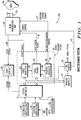
- FIG. 1 is a functional diagram of a directed energy system, including a target tracking system, in accordance with some embodiments.
- Directed energy system 100 includes, among other things, a target tracking system 120 and a beam transmission unit 108.
- the target tracking system 120 is configured to track a target 126, including one or more track points on the target 126.
- the beam transmission unit 108 is configured to maintain a directed energy beam 124 on a selected track point in response to tracking control signals 107 provided by the target tracking system 120.
- the track points is smaller than a spot size of the directed energy beam 124 that is maintained on the target 126 when the beam transmission unit 108 is transmitting.
- FIG. 2 is illustrates track points on an example target in accordance with some embodiments. As illustrated in FIG. 2 , one or more track points 202 on target 126 are tracked by target tracking system 120 ( FIG. 1 ). The track points 202 are configured to be smaller than a spot size 204 of the directed energy beam 124. Although FIG. 2 illustrates a human target, embodiments are equally suitable to almost any type of target.
- the target tracking system 120 includes a target identifier 102, a target tracker 104, and a tracking controller 106.
- the target identifier 102 receives video signals 109 and is configured to identify the target 126 from the background.
- the target identifier 102 is also configured to identify one or more track points 202 on the target 126.
- the target identifier 102 may be configured to separate target pixels from background pixels.
- the target identifier 102 may be configured to identify predetermined types of targets, such as human targets.
- the target tracker 104 tracks one or more of the track points 202 based on outputs 103 of the target identifier 102 and a rate-sensor signal 111.
- the tracking controller 106 generates the tracking control signals 107 based on outputs 105 of the target tracker 104 to control the beam transmission unit 108 for placement of a directed energy beam 124 on one of the track points 202.
- the target tracking system 120 may use rate sensors in the beam transmission unit 108 combined with optical tracking based on the video signals 109 to track at least one track point 202 as part of a tracking control loop in order to maintain the directed energy beam 124 on a selected one of the track points 202 for an amount of time to cause a deterring effect on the target 126.
- the target tracking system 120 can reduce and/or remove the effects of target movement and jitter.
- the amount of energy and/or time needed to cause a deterring effect on a moving target may be reduced, allowing for the use of more cost-effective solid-state components.
- Each of the one or more track points 202 may be a fraction of the spot size 204 of the directed energy beam 124 (e.g., less than half the diameter of the spot size 204). Since the diameter of a track point 202 is smaller (in some embodiments, much smaller) than the diameter of the spot size 204, tracking based on track points 202 is more accurate than the spot size 204.
- Tracking more accurately that the spot size 204 compensates at least in part for jitter and movement of the target 126.
- This allows less radio-frequency (RF) power to produce a desired effect (i.e., raise skin temperature) and deter the target 126.
- RF radio-frequency
- Lower RF power levels for example, allow lower-cost amplifiers to be used.
- the track points 202 may be approximately half an inch or less in diameter and the spot size 204 may be approximately one inch or less in diameter, although the scope of the embodiments is not limited in this respect.
- the minimum size of the directed energy beam 124 may be approximately four inches.
- the energy distribution of the directed energy beam 124 may have a Gaussian profile with a higher energy distribution toward the center of the spot size 204.
- the size of track points 202 may be selected so that the directed energy beam 124 can be maintained within a quarter of the beamwidth. For example, for a four-inch spot size, tracking points may be approximately three inches. In this way, tracking need not be more accurate than a quarter of the beamwidth, allowing for lower system power requirements, increased range capability, and reduced energy exposure to other parts of the target.
- the target tracker 104 is configured to track two or more track points 202.
- the tracking of two or more track points 202 that are smaller than the beam size is particularly advantageous to moving targets.
- Directed energy system 100 may also include a fire control element 116 configured to control an amount of time that the directed energy beam 124 is positioned on a selected one of the track points 202. The amount of time may be calculated to provide a minimum surface temperature rise based on a distance to the target 126 and the spot size 204 on the target 126.
- the fire control element 116 may determine a sufficient amount of time for the energy of beam 124 to be integrated and converted to a rise in skin temperature to deter the target 126. This is unlike some conventional directed energy systems that cover larger areas of a target to minimize tracking problems. These conventional systems require the generation of higher power levels to achieve a deterring effect on a target. As a result, these conventional systems are more costly and less effective with moving targets.
- a millimeter-wave amplifier within beam transmission unit 108 may be configured to generate a high-power output signal in response to a source control signal 117 provided by fire control element 116.
- the directed energy system 100 may also include a system controller 112 to control the various elements of directed energy system 100.
- the system controller 112 may cause the tracking controller 106 to focus and direct the directed energy beam 124 on a selected track point and may cause beam transmission unit 108 to maintain the directed energy beam 124 on the selected track point for the amount of time determined by the fire control element 116.
- the fire control element 116 may be configured to inhibit the directed energy beam 124 from being focused on the selected track point for greater periods of time to prevent a temperature rise above a predetermined maximum temperature.
- directed energy system 100 may include operator controls 114 to allow an operator to operate directed energy system 100.
- the operator may identify a target 126 on a video display 110 and may select one of the track points 202, which may be highlighted on the video display 110.
- the operator controls 114 may also be configured to allow the operator to fire the directed energy beam 124 in conjunction with the operations of fire control element 116.
- the fire control element 116 may be configured to inhibit the directing of the directed energy beam 124 on predetermined portions of a human body (e.g., the face, eyes, or head) even though one or more of the track points 202 may be provided on these portions of the target 126.
- the target identifier 102 may be configured to recognize images to distinguish between human and non-human images.
- the target identifier 102 may also be configured to identify particular portions of the human body (e.g., the face, eyes, or head) using feature-recognition algorithms to prevent such portions from being fired upon by directed energy beam 124.
- the target identifier 102 may be configured to identify a predetermined type of target (e.g., a human) within the video signals 109.
- the operator may identify a target 126 displayed on the video display 110 and may select the target 126 for tracking (i.e., by using a mouse or other input device through operator controls 114).
- the operator may also select one or more track points 202 on the target 126 for tracking by the target tracker 104.
- the operator may select a target 126 from several targets that may be displayed on the video display 110. This may allow the operator to identify a suspected intruder.
- the system controller 112 may be configured to provide system status information for display on the video display 110.
- the target identifier 102 may implement algorithms to recognize and identify humans, and may implement facial recognition software to identify facial features and to identify particular persons using the facial recognition software. In these embodiments, the target identifier 102 may be coupled to a database to allow particular persons to be identified and targeted.
- directed energy system 100 may also include calibration verification circuitry 128 to inhibit the directed energy beam 124 from being fired when the directed energy system 100 is not in calibration.
- Directed energy system 100 may also include location verification circuitry 130 to inhibit the directed energy system 100 from being operated when it is not in an approved or authorized location. The location verification circuitry 130 may use GPS location data and may include a GPS receiver.
- directed energy system 100 may also include authentication circuitry 132 to inhibit the directed energy beam 124 from being fired by unauthorized operators.
- system controller 112 may include decision logic to make the directed energy system 100 non-operational and/or non-functional depending on location verification, calibration verification, and user verification. In some of these embodiments, system controller 112 may include decision logic to verify that legal and operational guidelines are being followed and inhibit the operation of directed energy system 100 when legal and operational guidelines are not being followed.
- a method for operating a directed energy system such as directed energy system 100, is provided.
- operation of the directed energy system may be enabled when a calibration and a location are verified.
- Operation of the directed energy system may be disabled when the calibration or the location are not verified.
- Operation of the directed energy system may be disabled after a target exposure time is exceeded.
- Operation of the directed energy system may be enabled when a user is authenticated and may be disabled when the user is not able to be authenticated.
- the method may include verifying operational rules of engagement based on the calibration and the location, and disabling operation of the directed energy system when the operational rules of engagement are not met.
- the location may be verified based on GPS location information.
- directed energy system 100 is illustrated as having several separate functional elements, one or more of the functional elements may be combined and may be implemented by combinations of software configured elements, such as processing elements including digital signal processors (DSPs), and/or other hardware elements.
- processing elements including digital signal processors (DSPs), and/or other hardware elements.
- DSPs digital signal processors
- some elements may comprise one or more microprocessors, DSPs, application specific integrated circuits (ASICs), and combinations of various hardware and logic circuitry for performing at least the functions described herein.
- the functional elements of directed energy system 100 may refer to one or more processes operating on one or more processing elements.
- FIG. 3 is an illustrative diagram of a beam transmission unit in accordance with some embodiments.
- the beam transmission unit 108 illustrated in FIG. 3 may be suitable for use as the beam transmission unit 108 illustrated in FIG. 1 .
- Beam transmission unit 108 may include, among other things, a main antenna 310, a sub-reflector 306, and rate sensors 314.
- the video signals 109 may be generated by a video transmission unit 312 coupled to the main antenna 310 and directed to capture video in a transmission direction 311 of the main antenna 310.
- the tracking control signals 107 that are generated by the tracking controller 106 ( FIG. 1 ) may be configured to control the transmission direction 311 of the main antenna 310 when tracking the target 126 ( FIG.
- the rate sensors 314 may be configured to sense a rate of motion of the beam transmission unit 108 to provide the rate-sensor signal 111 for use by the target tracker 104 in tracking the track points 202 on the target 126 as part of a tracking control loop.
- the rate-sensor signal 111 may be used by the target tracker 104 ( FIG. 1 ) to correlate the rate-of-motion of the beam transmission unit 108 with motion of the target 126 and motion of the background within the video signals 109.
- the tracking controller 106 may generate the tracking control signals 107 to control the sub-reflector 306 for placement and focus of the directed energy beam 124 on a selected one of the track points 202 ( FIG. 2 ).
- the sub-reflector 306 may comprise a two-axis rotatable mirror whose position may be controlled by tracking control signals 107 to direct a high-power millimeter-wave signal 305 to a location on the main antenna 310 selected so that the directed energy beam 124 is placed on the selected track point 202.
- the position of the sub-reflector 306 may also be controlled to focus the directed energy beam 124 on the target 126 based on a distance to the target 126.
- the directed energy beam 124 may be a converging beam although this is not a requirement.
- the beam transmission unit 108 may include a laser range finder to determine the distance to the target 126.
- the main antenna 310 may be a parabolic surface antenna.
- the main antenna 310 may be a flat parabolic surface (FLAPS) antenna having a geometrically flat surface with an array of elements to allow it to operate electromagnetically as a parabolic reflector to generate a focused beam on the target 126.
- main antenna 310 may be configured to generate a directed energy beam 124 having a beam profile that limits the power density to portions of the target 126 outside the selected track point. In these embodiments, the beam profile may be selected for a particular distance and antenna size.
- the beam transmission unit 108 may also include a millimeter-wave amplifier 302 and transmit (TX) antenna 304 to generate the high-power millimeter-wave signal 305.
- the millimeter-wave amplifier 302 is a solid-state amplifier configured to generate a high-power millimeter-wave signal having a frequency between 94 and 96 GHz.
- Millimeter-wave amplifier 302 may be configured to generate a high-power output signal in response to source control signal 117, which may be provided by fire control element 116 ( FIG. 1 ).
- the various elements of the beam transmission unit 108 may be mounted on a single platform and configured to move as a single unit.
- the single platform may be gimbaled to allow three-directional target tracking and placement of the directed energy beam 124.
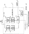
- FIG. 4 is a functional block diagram of a target tracker in accordance with some embodiments.
- target tracker 400 illustrated in FIG. 4 , may be suitable for use as the target tracker 104 ( FIG. 1 ), although other target trackers may also be suitable.
- the target tracker 400 may include a target tracking element 402 to track the one or more track points 202 ( FIG. 2 ) based on features of the target 126 ( FIG. 1 ) identified by the target identifier 102 ( FIG. 1 ).
- the target tracker 400 may also include a background tracking element 404 to track a background portion of a field-of-view of the video transmission unit 312 ( FIG. 3 ).
- the target tracking element 402 may be responsive to changes in the background portion to identify a target portion of the field of view. For example, the target tracking element 402 may detect changes in background pixels to track the target 126 ( FIG. 2 ). In some embodiments, the background tracking element 404 may execute a re-registration algorithm to distinguish the background from the target 126.
- the target tracking element 402 may be a multi-point target tracking element 402 configured to track two or more track points 202 on the target 126. In this way, some track points may be maintained as the target 126 moves, changes position, and turns around. Furthermore, tracking controller 106 ( FIG. 1 ) may be configured to quickly switch between track points for placement of the directed energy beam 124.
- target tracker 400 may include a target dynamics processing element 406 to process target movement and compute a dynamic error signal for the target 126, and a background dynamics processing element 408 to process background movement and compute a dynamic error signal for the background.
- the target tracker 400 may also include a Kalman filter 410 responsive to dynamic error signals to generate the outputs for tracking controller 106 ( FIG. 1 ).
- the target tracker 400 may also include a computed effect level processing element 412 to compute a time, a distance, and amount of target jitter for use by the fire control element 116 ( FIG. 1 ).
- the fire control element 116 may be response to outputs of the computed effect level processing element 412. For example, the time that directed energy beam 124 is placed on a track point may be increased with increased amounts of target jitter to achieve a desired effect.
- the Kalman filter 410 may use the dynamic error signals from the target and background dynamics processing elements 406 and 408 not only to provide an estimate of the present location of the target 126, but to predict future positions of the target 126 to assist in target tracking. In some embodiments, these separate error signals may be processed separately for optimal target tracking.
- the target tracker 104 uses a tracking guidance loop error signal that is run to a beam-angle controller as part of tracking control signals 107 to optically maintain the directed energy beam 124 on a selected tracking point.
- the target tracker 104 may use higher order and predictive guidance tracking processes to allow for tight tracking even under acceleration conditions.
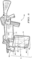
- FIG. 5 illustrates an example hand-held directed energy system that includes a target tracking system in accordance with some embodiments.
- Hand-held directed energy system 500 may include the functional elements of the directed energy system 100 ( FIG. 1 ).
- the hand-held directed energy system 500 includes main antenna 310, sub-reflector 306 and transmit antenna 304 illustrated separately.
- the other functional components of the directed energy system 100 may be located internally.
- Hand-held directed energy system 500 may track one or more track points on a target based on outputs of a target identifier.
- Hand-held directed energy system 500 may also generate tracking control signals based on outputs of the target tracker to control a beam transmission unit for placement of a directed energy beam 124 on one of the track points. Accordingly, a target may be deterred without the use of lethal force.
Landscapes
- Engineering & Computer Science (AREA)
- General Engineering & Computer Science (AREA)
- Physics & Mathematics (AREA)
- Radar, Positioning & Navigation (AREA)
- Remote Sensing (AREA)
- Electromagnetism (AREA)
- General Physics & Mathematics (AREA)
- Optical Radar Systems And Details Thereof (AREA)
- Radar Systems Or Details Thereof (AREA)
Claims (14)
- System zur Zielverfolgung (120), ausgelegt zur Verwendung in einem gezielten Energiesystem (100), wobei das System zur Zielverfolgung umfasst:eine Zielkennung (102), ausgelegt zum Empfangen von Videosignalen (109) zum Trennen eines Track-Punkte (202) aufweisenden Ziels (126) von einem Hintergrund und zum Identifizieren von einem oder mehreren Track-Punkten (202) an dem Ziel (126), wobei die Durchmesser des einen oder der mehreren identifizierten Track-Punkte dafür ausgelegt sind, kleiner zu sein als ein Durchmesser des Spots (204) eines gezielten Energiestrahls (124) des gezielten Energiesystems (100) an dem Ziel, um es dem gezielten Energiestrahl (124) zu ermöglichen, einen ausgewählten Track-Punkt zum Kompensieren von Jitter auszuwählen;einen Zielverfolger (104), ausgelegt zum Verfolgen von einem oder mehreren Track-Punkten an dem Ziel, basierend auf Ausgaben (103) der Zielkennung; undeine Verfolgungssteuerung (106), ausgelegt zum Erzeugen von Verfolgungssteuersignalen (107) basierend auf Ausgaben (105) des Zielverfolgers zum Steuern einer Strahlübertragungseinheit (108) des gezielten Energiesystems (100) zum Platzieren eines gezielten Energiestrahls (124) an einem ausgewählten der Track-Punkte zum Ausstrahlen zu einem Teil des Ziels.
- System nach Anspruch 1, wobei die Strahlübertragungseinheit einen oder mehrere Ratensensoren (314) umfasst, ausgelegt zum Abtasten einer Bewegungsrate der Strahlübertragungseinheit und zum Bereitstellen eines Ratensensorsignals (111) zur Verwendung durch den Zielverfolger zum Verfolgen des einen Track-Punkts oder der mehreren Track-Punkte an dem Ziel als Teil einer Verfolgungssteuerschleife.
- System nach Anspruch 2, wobei die Strahlübertragungseinheit eine Haupt-Reflektorantenne (310) und einen Subreflektor (306) umfasst,
wobei die Videosignale (109) durch eine Videoübertragungseinheit (312) erzeugt werden, die mit der Haupt-Reflektorantenne gekoppelt ist und gerichtet ist auf das Erfassen von Video in einer Übertragungsrichtung (311) der Haupt-Reflektorantenne,
wobei die Verfolgungssteuersignale ferner dafür ausgelegt sind, die Übertragungsrichtung der Haupt-Reflektorantenne zu steuern, wenn ein Ziel verfolgt wird, um das Ziel in einem Sichtfeld der Videoübertragungseinheit zu halten, und
wobei die Verfolgungssteuerung dafür ausgelegt ist, die Verfolgungssteuersignale zu erzeugen, um den Subreflektor zum Platzieren und Fokussieren des gezielten Energiestrahls auf einen ausgewählten der Track-Punkte zu steuern,
wobei das gezielte Energiesystem ferner ein Auslöse-Steuerelement (116) umfasst, dafür ausgelegt, einen Zeitraum zu steuern, über den der gezielte Energiestrahl auf dem ausgewählten Track-Punkt positioniert ist,
wobei der Zeitraum berechnet wird, um einen Anstieg einer Oberflächentemperatur basierend auf einer Distanz zu dem Ziel und der Spot-Größe an dem Ziel bereitzustellen,
wobei das gezielte Energiesystem ferner eine Systemsteuerung (112) umfasst,
wobei die Systemsteuerung als Reaktion auf ein Strahlauslösesignal dafür ausgelegt ist, die Verfolgungssteuerung zu veranlassen, den gezielten Energiestrahl auf den ausgewählten Track-Punkt zu fokussieren und zu leiten und den gezielten Energiestrahl auf dem ausgewählten Track-Punkt beizubehalten, während das Ziel sich über den für das Auslöse-Steuerelement festgelegten Zeitraum bewegt,
wobei das Auslöse-Steuerelement dafür ausgelegt ist, den gezielten Energiestrahl daran zu hindern, über längere Zeiträume auf den ausgewählten Track-Punkt fokussiert zu bleiben, um einen Temperaturanstieg über eine vorbestimmte Maximaltemperatur zu verhindern,
wobei das Auslöse-Steuerelement ferner dafür ausgelegt ist, die Lenkung des gezielten Energiestrahls zu vorbestimmten Teilen eines menschlichen Körpers zu verhindern, auch wenn ein oder mehrere Track-Punkte auf den vorbestimmten Teilen bereitgestellt sein können. - System zur Zielverfolgung nach Anspruch 1, wobei der Zielverfolger umfasst:ein Zielverfolgungselement (402), ausgelegt zum Verfolgen des einen oder der mehreren Track-Punkte basierend auf Merkmalen des durch die Zielkennung identifizierten Ziels (126); undein Hintergrund-Verfolgungselement (404), ausgelegt zum Verfolgen eines Hintergrundabschnitts eines Sichtfelds einer Videoübertragungseinheit,wobei das Zielverfolgungselement dafür ausgelegt ist, auf Änderungen in dem Hintergrundabschnitt zu reagieren, um einen Zielabschnitt des Sichtfelds zu identifizieren.
- System zur Zielverfolgung nach Anspruch 4, wobei das Zielverfolgungselement ein Mehrpunkt-Zielverfolgungselement ist, dafür ausgelegt, zwei oder mehr Track-Punkte an dem Ziel zu verfolgen.
- System zur Zielverfolgung nach Anspruch 4, wobei der Zielverfolger ferner umfasst:ein Zieldynamik-Verarbeitungselement (406), ausgelegt zum Verarbeiten von Zielbewegung und Berechnen eines dynamischen Fehlersignals für das Ziel;ein Hintergrunddynamik-Verarbeitungselement (408), dafür ausgelegt, Hintergrundbewegung zu verarbeiten und ein dynamisches Fehlersignal für den Hintergrund zu berechnen;ein Kalman-Filter (410), dafür ausgelegt, auf die dynamischen Fehlersignale zu reagieren, um die Verfolgungssteuersignale zu erzeugen; undein Verarbeitungselement (412) für berechnete Wirkungsebenen, dafür ausgelegt, eine Zeit, eine Distanz und einen Umfang von Ziel-Jitter für ein Auslöse-Steuerelement zu berechnen,wobei das Auslöse-Steuerelement dafür ausgelegt ist, auf Ausgaben des Verarbeitungselements der berechneten Wirkungsebene zu reagieren, um die Zeit mit größeren Umfängen von Ziel-Jitter zu erhöhen, um einen erwünschten Effekt zu erzielen.
- System zur Zielverfolgung nach Anspruch 1, wobei die Zielkennung dafür ausgelegt ist, ein menschliches Ziel innerhalb der Videosignale zu identifizieren und den einen oder die mehreren Track-Punkte an dem menschlichen Ziel zu identifizieren.
- Gezieltes Energiesystem, umfassend:das System zur Zielverfolgung nach Anspruch 1; undeine Strahlübertragungseinheit, ausgelegt zum Beibehalten eines gezielten Energiestrahls an einem ausgewählten der Track-Punkte als Reaktion auf Verfolgungssteuersignale, bereitgestellt durch das System zur Zielverfolgung.
- System nach Anspruch 8, wobei die Strahlübertragungseinheit einen oder mehrere Ratensensoren umfasst, ausgelegt zum Abtasten einer Bewegungsrate der Strahlübertragungseinheit und zum Bereitstellen des Ratensensorsignals zur Verwendung durch den Zielverfolger zum Verfolgen des einen Track-Punkts oder der mehreren Track-Punkte an dem Ziel als Teil einer Verfolgungssteuerschleife.
- System nach Anspruch 9, wobei die Strahlübertragungseinheit eine Haupt-Reflektorantenne und einen Subreflektor umfasst,
wobei das System ferner eine mit der Haupt-Reflektorantenne gekoppelte Videoübertragungseinheit umfasst, gerichtet auf das Erfassen von Video in einer Übertragungsrichtung der Haupt-Reflektorantenne und ausgelegt zum Erzeugen des Videosignals,
wobei die Verfolgungssteuersignale ferner dafür ausgelegt sind, die Übertragungsrichtung der Haupt-Reflektorantenne zu steuern, wenn das Ziel verfolgt wird, um das Ziel in einem Sichtfeld der Videoübertragungseinheit zu halten, und
wobei die Verfolgungssteuerung dafür ausgelegt ist, die Verfolgungssteuersignale zu erzeugen, um den Subreflektor zum Platzieren und Fokussieren des gezielten Energiestrahls auf einen ausgewählten der Track-Punkte zu steuern. - System nach Anspruch 9, wobei die Strahlübertragungseinheit ferner einen Millimeterwellenverstärker umfasst,
wobei der Millimeterwellenverstärker ein Solid-State-Verstärker ist, ausgelegt zum Erzeugen eines Hochleistungs-Millimeterwellensignals, das eine Frequenz zwischen 94 und 96 GHz aufweist, und
wobei die Haupt-Reflektorantenne eine flache Antenne mit parabolischer Oberfläche umfasst, aufweisend eine geometrisch flache Oberfläche mit einem Array von Elementen, um es der Hauptantenne zu ermöglichen, elektromagnetisch als ein Parabolreflektor zu wirken, um einen fokussierten Strahl an dem Ziel zu erzeugen. - System nach Anspruch 10, ferner umfassend ein Auslöse-Steuerelement, dafür ausgelegt, einen Zeitraum zu steuern, über den der gezielte Energiestrahl an einem ausgewählten der Track-Punkte positioniert ist,
wobei der Zeitraum berechnet wird, um einen Anstieg einer Oberflächentemperatur basierend auf einer Distanz zu dem Ziel und der Spot-Größe an dem Ziel bereitzustellen. - Verhinderungsverfahren für ein Track-Punkte aufweisendes Ziel, umfassend:optisches Verfolgen von einem oder mehreren Track-Punkten an dem Ziel bei der Bewegung des Ziels, wobei jeder Track-Punkt einen Durchmesser aufweist;Verwenden einer Bewegungsrate einer Strahlübertragungseinheit zum Aufrechterhalten eines gezielten Energiestrahls an einem ausgewählten der Track-Punkte mit einer Verfolgungssteuerschleife, um auf einen Abschnitt des Ziels abzustrahlen; undBeibehalten des gezielten Energiestrahls an dem ausgewählten Track-Punkt über einen Zeitraum, um einen Verhinderungseffekt zu bewirken, indem die Oberflächentemperatur in dem ausgewählten Track-Punkt erhöht wird,wobei die Durchmesser der ein oder mehreren Track-Punkte dafür ausgelegt sind, kleiner zu sein als ein Durchmesser des Spots des gezielten Energiestrahls an dem Ziel, um dem gezielten Energiestrahl das Abdecken des ausgewählten Track-Punkts zu ermöglichen, um Ziel-Jitter zu kompensieren und den Verhinderungseffekt zu bewirken.
- Verfahren nach Anspruch 13, wobei die Strahlübertragungseinheit dafür ausgelegt ist, den gezielten Energiestrahl zu erzeugen und
wobei das Verfahren ferner das Reduzieren der Effekte von Jitter und Zielbewegung unter Verwendung der Bewegungsrate umfasst.
Applications Claiming Priority (2)
| Application Number | Priority Date | Filing Date | Title |
|---|---|---|---|
| US5690508P | 2008-05-29 | 2008-05-29 | |
| PCT/US2009/003278 WO2009145904A1 (en) | 2008-05-29 | 2009-05-29 | Target tracking system and method with jitter reduction suitable for directed energy systems |
Publications (3)
| Publication Number | Publication Date |
|---|---|
| EP2281285A1 EP2281285A1 (de) | 2011-02-09 |
| EP2281285A4 EP2281285A4 (de) | 2015-05-20 |
| EP2281285B1 true EP2281285B1 (de) | 2019-12-11 |
Family
ID=41377438
Family Applications (1)
| Application Number | Title | Priority Date | Filing Date |
|---|---|---|---|
| EP09755267.3A Active EP2281285B1 (de) | 2008-05-29 | 2009-05-29 | System und verfahren zur zielverfolgung mit jitterunterdrückung für gezielte energiesysteme |
Country Status (3)
| Country | Link |
|---|---|
| US (1) | US8188905B2 (de) |
| EP (1) | EP2281285B1 (de) |
| WO (1) | WO2009145904A1 (de) |
Families Citing this family (9)
| Publication number | Priority date | Publication date | Assignee | Title |
|---|---|---|---|---|
| US8923359B1 (en) * | 2010-08-06 | 2014-12-30 | Lockheed Martin Corporation | Long cavity laser sensor for large FOV auto-tracking |
| FR2970072B1 (fr) * | 2010-12-29 | 2013-02-08 | Thales Sa | Procede et dispositif de neutralisation d'une cible |
| IL211966A (en) * | 2011-03-28 | 2016-12-29 | Smart Shooter Ltd | Weapons, a direction system for him, his method of operation, and a method of reducing the chance of a sin's purpose |
| CN103759579B (zh) * | 2014-01-20 | 2016-04-13 | 成都华之芯科技有限公司 | 一种拒止系统 |
| CN103760913B (zh) * | 2014-01-20 | 2016-05-04 | 成都华之芯科技有限公司 | 一种毫米波拒止系统的扫描控制系统 |
| DE102014114036A1 (de) * | 2014-09-26 | 2016-03-24 | Cassidian Optronics Gmbh | Richt- und Leitvorrichtung sowie Verfahren zur Unterstützung eines Richtschützen eines Waffensystems |
| DE102017007837A1 (de) * | 2017-08-18 | 2019-02-21 | Thomas Samland | Nicht-letales Wirkmittel |
| US11536543B2 (en) * | 2020-01-27 | 2022-12-27 | Raytheon Company | Directed energy (DE) weapon and passive millimeter wave (PmmW) imager for target tracking |
| US11231252B2 (en) * | 2020-06-10 | 2022-01-25 | Brett C. Bilbrey | Method for automated weapon system with target selection of selected types of best shots |
Family Cites Families (16)
| Publication number | Priority date | Publication date | Assignee | Title |
|---|---|---|---|---|
| US3952304A (en) | 1973-11-23 | 1976-04-20 | Hughes Aircraft Company | Tracking system utilizing Kalman filter concepts |
| DE4444637C2 (de) * | 1994-12-15 | 1996-09-26 | Sepp Gunther | Laser-Waffensystem |
| US6839662B2 (en) * | 2001-08-17 | 2005-01-04 | Lockheed Martin Corporation | Command and control system architecture for convenient upgrading |
| IL145730A0 (en) * | 2001-10-01 | 2003-06-24 | Rafael Armament Dev Authority | Improved directional infrared counter measure |
| US6965816B2 (en) * | 2001-10-01 | 2005-11-15 | Kline & Walker, Llc | PFN/TRAC system FAA upgrades for accountable remote and robotics control to stop the unauthorized use of aircraft and to improve equipment management and public safety in transportation |
| US7126530B2 (en) * | 2004-04-20 | 2006-10-24 | Raytheon Company | Non-coherent high-power directed-energy system and method |
| FR2881532B1 (fr) * | 2005-02-01 | 2007-05-18 | Commissariat Energie Atomique | Procede de mise en oeuvre d'un ensemble rayonnant de puissance ayant une portee kilometrique |
| US7164234B2 (en) * | 2005-03-18 | 2007-01-16 | L-3 Communications Corporation | High-power microwave system employing a phase-locked array of inexpensive commercial magnetrons |
| US7490538B2 (en) * | 2005-08-18 | 2009-02-17 | Raytheon Company | Weapon having lethal and non-lethal directed-energy portions |
| US7641153B2 (en) * | 2005-11-21 | 2010-01-05 | The Boeing Company | Directed energy off-body heating for supersonic vehicle shockwave and sonic boom control |
| US7504982B2 (en) * | 2005-12-06 | 2009-03-17 | Raytheon Company | Anti-Missile system and method |
| US7629918B2 (en) * | 2005-12-15 | 2009-12-08 | Raytheon Company | Multifunctional radio frequency directed energy system |
| KR20090031346A (ko) | 2006-04-10 | 2009-03-25 | 엘타 시스템즈 리미티드 | 분산 전파방해 시스템 |
| US7626152B2 (en) * | 2006-08-16 | 2009-12-01 | Raytheon Company | Beam director and control system for a high energy laser within a conformal window |
| US7961133B2 (en) * | 2007-11-15 | 2011-06-14 | Raytheon Company | System and method for diverting a guided missile |
| US7978313B2 (en) * | 2008-05-30 | 2011-07-12 | The Boeing Company | Systems and methods for targeting directed energy devices |
-
2009
- 2009-05-29 WO PCT/US2009/003278 patent/WO2009145904A1/en not_active Ceased
- 2009-05-29 US US12/474,483 patent/US8188905B2/en active Active
- 2009-05-29 EP EP09755267.3A patent/EP2281285B1/de active Active
Non-Patent Citations (1)
| Title |
|---|
| None * |
Also Published As
| Publication number | Publication date |
|---|---|
| WO2009145904A1 (en) | 2009-12-03 |
| EP2281285A4 (de) | 2015-05-20 |
| EP2281285A1 (de) | 2011-02-09 |
| US8188905B2 (en) | 2012-05-29 |
| US20120104282A1 (en) | 2012-05-03 |
Similar Documents
| Publication | Publication Date | Title |
|---|---|---|
| EP2281285B1 (de) | System und verfahren zur zielverfolgung mit jitterunterdrückung für gezielte energiesysteme | |
| AU2007237067B2 (en) | Distributed jammer system | |
| JP4422730B2 (ja) | ミリ波領域保護システムおよび方法 | |
| US6674520B2 (en) | Closed-loop infrared countermeasure system using a high frame rate infrared receiver with nulling sequence | |
| US7952691B2 (en) | Method and system of aligning a track beam and a high energy laser beam | |
| US20110036999A1 (en) | Countermeasure method for a mobile tracking device | |
| JP3222837B2 (ja) | 画像化自己参照追跡装置及び関連方法 | |
| US20210083395A1 (en) | Method and apparatus for object detection incorporating metamaterial antenna side lobe features | |
| US20130082183A1 (en) | Directed infra-red countermeasure system | |
| JP2020533559A (ja) | アクティブシーカーヘッドシステム | |
| EP3631499B1 (de) | Waffensystem | |
| AU2018277595B2 (en) | Weapon system | |
| GB2565200A (en) | Weapon system | |
| JP2017101894A (ja) | レーザ防御システム、および、レーザ防御方法 | |
| KR100552385B1 (ko) | 적외선 플레어를 이용한 지향성 적외선 방해 장치 | |
| US20220385020A1 (en) | Perception Prediction Illumination Feedback | |
| KR102564734B1 (ko) | 레이저를 이용한 유도 무기 무력화 시스템 및 유도 무기 무력화 방법 | |
| CN121761704A (zh) | 一种用于城市作战环境的低可探测性主被动复合致盲系统 | |
| EP3410149A1 (de) | Waffensystem | |
| GB2386015A (en) | Closed-loop infrared countermeasure system using high frame rate infrared receiver | |
| EP3410148A1 (de) | Waffensystem |
Legal Events
| Date | Code | Title | Description |
|---|---|---|---|
| PUAI | Public reference made under article 153(3) epc to a published international application that has entered the european phase |
Free format text: ORIGINAL CODE: 0009012 |
|
| 17P | Request for examination filed |
Effective date: 20101126 |
|
| AK | Designated contracting states |
Kind code of ref document: A1 Designated state(s): AT BE BG CH CY CZ DE DK EE ES FI FR GB GR HR HU IE IS IT LI LT LU LV MC MK MT NL NO PL PT RO SE SI SK TR |
|
| AX | Request for extension of the european patent |
Extension state: AL BA RS |
|
| DAX | Request for extension of the european patent (deleted) | ||
| RA4 | Supplementary search report drawn up and despatched (corrected) |
Effective date: 20150417 |
|
| RIC1 | Information provided on ipc code assigned before grant |
Ipc: F41G 3/16 20060101ALI20150413BHEP Ipc: F41H 13/00 20060101AFI20150413BHEP Ipc: F41G 3/12 20060101ALI20150413BHEP Ipc: G01S 3/786 20060101ALI20150413BHEP |
|
| STAA | Information on the status of an ep patent application or granted ep patent |
Free format text: STATUS: EXAMINATION IS IN PROGRESS |
|
| 17Q | First examination report despatched |
Effective date: 20180628 |
|
| GRAP | Despatch of communication of intention to grant a patent |
Free format text: ORIGINAL CODE: EPIDOSNIGR1 |
|
| STAA | Information on the status of an ep patent application or granted ep patent |
Free format text: STATUS: GRANT OF PATENT IS INTENDED |
|
| INTG | Intention to grant announced |
Effective date: 20190704 |
|
| GRAS | Grant fee paid |
Free format text: ORIGINAL CODE: EPIDOSNIGR3 |
|
| GRAA | (expected) grant |
Free format text: ORIGINAL CODE: 0009210 |
|
| STAA | Information on the status of an ep patent application or granted ep patent |
Free format text: STATUS: THE PATENT HAS BEEN GRANTED |
|
| AK | Designated contracting states |
Kind code of ref document: B1 Designated state(s): AT BE BG CH CY CZ DE DK EE ES FI FR GB GR HR HU IE IS IT LI LT LU LV MC MK MT NL NO PL PT RO SE SI SK TR |
|
| REG | Reference to a national code |
Ref country code: GB Ref legal event code: FG4D |
|
| REG | Reference to a national code |
Ref country code: CH Ref legal event code: EP |
|
| REG | Reference to a national code |
Ref country code: AT Ref legal event code: REF Ref document number: 1212616 Country of ref document: AT Kind code of ref document: T Effective date: 20191215 |
|
| REG | Reference to a national code |
Ref country code: DE Ref legal event code: R096 Ref document number: 602009060684 Country of ref document: DE |
|
| REG | Reference to a national code |
Ref country code: IE Ref legal event code: FG4D |
|
| REG | Reference to a national code |
Ref country code: NL Ref legal event code: MP Effective date: 20191211 |
|
| REG | Reference to a national code |
Ref country code: LT Ref legal event code: MG4D |
|
| PG25 | Lapsed in a contracting state [announced via postgrant information from national office to epo] |
Ref country code: LV Free format text: LAPSE BECAUSE OF FAILURE TO SUBMIT A TRANSLATION OF THE DESCRIPTION OR TO PAY THE FEE WITHIN THE PRESCRIBED TIME-LIMIT Effective date: 20191211 Ref country code: SE Free format text: LAPSE BECAUSE OF FAILURE TO SUBMIT A TRANSLATION OF THE DESCRIPTION OR TO PAY THE FEE WITHIN THE PRESCRIBED TIME-LIMIT Effective date: 20191211 Ref country code: ES Free format text: LAPSE BECAUSE OF FAILURE TO SUBMIT A TRANSLATION OF THE DESCRIPTION OR TO PAY THE FEE WITHIN THE PRESCRIBED TIME-LIMIT Effective date: 20191211 Ref country code: LT Free format text: LAPSE BECAUSE OF FAILURE TO SUBMIT A TRANSLATION OF THE DESCRIPTION OR TO PAY THE FEE WITHIN THE PRESCRIBED TIME-LIMIT Effective date: 20191211 Ref country code: GR Free format text: LAPSE BECAUSE OF FAILURE TO SUBMIT A TRANSLATION OF THE DESCRIPTION OR TO PAY THE FEE WITHIN THE PRESCRIBED TIME-LIMIT Effective date: 20200312 Ref country code: NO Free format text: LAPSE BECAUSE OF FAILURE TO SUBMIT A TRANSLATION OF THE DESCRIPTION OR TO PAY THE FEE WITHIN THE PRESCRIBED TIME-LIMIT Effective date: 20200311 Ref country code: FI Free format text: LAPSE BECAUSE OF FAILURE TO SUBMIT A TRANSLATION OF THE DESCRIPTION OR TO PAY THE FEE WITHIN THE PRESCRIBED TIME-LIMIT Effective date: 20191211 Ref country code: BG Free format text: LAPSE BECAUSE OF FAILURE TO SUBMIT A TRANSLATION OF THE DESCRIPTION OR TO PAY THE FEE WITHIN THE PRESCRIBED TIME-LIMIT Effective date: 20200311 |
|
| PG25 | Lapsed in a contracting state [announced via postgrant information from national office to epo] |
Ref country code: HR Free format text: LAPSE BECAUSE OF FAILURE TO SUBMIT A TRANSLATION OF THE DESCRIPTION OR TO PAY THE FEE WITHIN THE PRESCRIBED TIME-LIMIT Effective date: 20191211 |
|
| PG25 | Lapsed in a contracting state [announced via postgrant information from national office to epo] |
Ref country code: CZ Free format text: LAPSE BECAUSE OF FAILURE TO SUBMIT A TRANSLATION OF THE DESCRIPTION OR TO PAY THE FEE WITHIN THE PRESCRIBED TIME-LIMIT Effective date: 20191211 Ref country code: RO Free format text: LAPSE BECAUSE OF FAILURE TO SUBMIT A TRANSLATION OF THE DESCRIPTION OR TO PAY THE FEE WITHIN THE PRESCRIBED TIME-LIMIT Effective date: 20191211 Ref country code: PT Free format text: LAPSE BECAUSE OF FAILURE TO SUBMIT A TRANSLATION OF THE DESCRIPTION OR TO PAY THE FEE WITHIN THE PRESCRIBED TIME-LIMIT Effective date: 20200506 Ref country code: EE Free format text: LAPSE BECAUSE OF FAILURE TO SUBMIT A TRANSLATION OF THE DESCRIPTION OR TO PAY THE FEE WITHIN THE PRESCRIBED TIME-LIMIT Effective date: 20191211 Ref country code: NL Free format text: LAPSE BECAUSE OF FAILURE TO SUBMIT A TRANSLATION OF THE DESCRIPTION OR TO PAY THE FEE WITHIN THE PRESCRIBED TIME-LIMIT Effective date: 20191211 |
|
| PG25 | Lapsed in a contracting state [announced via postgrant information from national office to epo] |
Ref country code: IS Free format text: LAPSE BECAUSE OF FAILURE TO SUBMIT A TRANSLATION OF THE DESCRIPTION OR TO PAY THE FEE WITHIN THE PRESCRIBED TIME-LIMIT Effective date: 20200411 Ref country code: SK Free format text: LAPSE BECAUSE OF FAILURE TO SUBMIT A TRANSLATION OF THE DESCRIPTION OR TO PAY THE FEE WITHIN THE PRESCRIBED TIME-LIMIT Effective date: 20191211 |
|
| REG | Reference to a national code |
Ref country code: DE Ref legal event code: R097 Ref document number: 602009060684 Country of ref document: DE |
|
| REG | Reference to a national code |
Ref country code: AT Ref legal event code: MK05 Ref document number: 1212616 Country of ref document: AT Kind code of ref document: T Effective date: 20191211 |
|
| PLBE | No opposition filed within time limit |
Free format text: ORIGINAL CODE: 0009261 |
|
| STAA | Information on the status of an ep patent application or granted ep patent |
Free format text: STATUS: NO OPPOSITION FILED WITHIN TIME LIMIT |
|
| PG25 | Lapsed in a contracting state [announced via postgrant information from national office to epo] |
Ref country code: DK Free format text: LAPSE BECAUSE OF FAILURE TO SUBMIT A TRANSLATION OF THE DESCRIPTION OR TO PAY THE FEE WITHIN THE PRESCRIBED TIME-LIMIT Effective date: 20191211 |
|
| 26N | No opposition filed |
Effective date: 20200914 |
|
| PG25 | Lapsed in a contracting state [announced via postgrant information from national office to epo] |
Ref country code: PL Free format text: LAPSE BECAUSE OF FAILURE TO SUBMIT A TRANSLATION OF THE DESCRIPTION OR TO PAY THE FEE WITHIN THE PRESCRIBED TIME-LIMIT Effective date: 20191211 Ref country code: AT Free format text: LAPSE BECAUSE OF FAILURE TO SUBMIT A TRANSLATION OF THE DESCRIPTION OR TO PAY THE FEE WITHIN THE PRESCRIBED TIME-LIMIT Effective date: 20191211 Ref country code: SI Free format text: LAPSE BECAUSE OF FAILURE TO SUBMIT A TRANSLATION OF THE DESCRIPTION OR TO PAY THE FEE WITHIN THE PRESCRIBED TIME-LIMIT Effective date: 20191211 |
|
| PG25 | Lapsed in a contracting state [announced via postgrant information from national office to epo] |
Ref country code: IT Free format text: LAPSE BECAUSE OF FAILURE TO SUBMIT A TRANSLATION OF THE DESCRIPTION OR TO PAY THE FEE WITHIN THE PRESCRIBED TIME-LIMIT Effective date: 20191211 Ref country code: MC Free format text: LAPSE BECAUSE OF FAILURE TO SUBMIT A TRANSLATION OF THE DESCRIPTION OR TO PAY THE FEE WITHIN THE PRESCRIBED TIME-LIMIT Effective date: 20191211 Ref country code: LI Free format text: LAPSE BECAUSE OF NON-PAYMENT OF DUE FEES Effective date: 20200531 Ref country code: CH Free format text: LAPSE BECAUSE OF NON-PAYMENT OF DUE FEES Effective date: 20200531 |
|
| REG | Reference to a national code |
Ref country code: BE Ref legal event code: MM Effective date: 20200531 |
|
| PG25 | Lapsed in a contracting state [announced via postgrant information from national office to epo] |
Ref country code: LU Free format text: LAPSE BECAUSE OF NON-PAYMENT OF DUE FEES Effective date: 20200529 |
|
| PG25 | Lapsed in a contracting state [announced via postgrant information from national office to epo] |
Ref country code: IE Free format text: LAPSE BECAUSE OF NON-PAYMENT OF DUE FEES Effective date: 20200529 |
|
| PG25 | Lapsed in a contracting state [announced via postgrant information from national office to epo] |
Ref country code: BE Free format text: LAPSE BECAUSE OF NON-PAYMENT OF DUE FEES Effective date: 20200531 |
|
| PG25 | Lapsed in a contracting state [announced via postgrant information from national office to epo] |
Ref country code: TR Free format text: LAPSE BECAUSE OF FAILURE TO SUBMIT A TRANSLATION OF THE DESCRIPTION OR TO PAY THE FEE WITHIN THE PRESCRIBED TIME-LIMIT Effective date: 20191211 Ref country code: MT Free format text: LAPSE BECAUSE OF FAILURE TO SUBMIT A TRANSLATION OF THE DESCRIPTION OR TO PAY THE FEE WITHIN THE PRESCRIBED TIME-LIMIT Effective date: 20191211 Ref country code: CY Free format text: LAPSE BECAUSE OF FAILURE TO SUBMIT A TRANSLATION OF THE DESCRIPTION OR TO PAY THE FEE WITHIN THE PRESCRIBED TIME-LIMIT Effective date: 20191211 |
|
| PG25 | Lapsed in a contracting state [announced via postgrant information from national office to epo] |
Ref country code: MK Free format text: LAPSE BECAUSE OF FAILURE TO SUBMIT A TRANSLATION OF THE DESCRIPTION OR TO PAY THE FEE WITHIN THE PRESCRIBED TIME-LIMIT Effective date: 20191211 |
|
| P01 | Opt-out of the competence of the unified patent court (upc) registered |
Effective date: 20230530 |
|
| PGFP | Annual fee paid to national office [announced via postgrant information from national office to epo] |
Ref country code: DE Payment date: 20250423 Year of fee payment: 17 |
|
| PGFP | Annual fee paid to national office [announced via postgrant information from national office to epo] |
Ref country code: GB Payment date: 20250423 Year of fee payment: 17 |
|
| PGFP | Annual fee paid to national office [announced via postgrant information from national office to epo] |
Ref country code: FR Payment date: 20250423 Year of fee payment: 17 |