EP2281397B1 - Dispositif d éclairage et d affichage - Google Patents
Dispositif d éclairage et d affichage Download PDFInfo
- Publication number
- EP2281397B1 EP2281397B1 EP09757276.2A EP09757276A EP2281397B1 EP 2281397 B1 EP2281397 B1 EP 2281397B1 EP 09757276 A EP09757276 A EP 09757276A EP 2281397 B1 EP2281397 B1 EP 2281397B1
- Authority
- EP
- European Patent Office
- Prior art keywords
- lighting
- light
- display
- light emission
- emission surface
- Prior art date
- Legal status (The legal status is an assumption and is not a legal conclusion. Google has not performed a legal analysis and makes no representation as to the accuracy of the status listed.)
- Active
Links
- 238000005286 illumination Methods 0.000 title description 15
- 238000009413 insulation Methods 0.000 claims description 7
- 239000000463 material Substances 0.000 claims description 6
- 239000004973 liquid crystal related substance Substances 0.000 claims description 4
- 230000000694 effects Effects 0.000 description 3
- 230000005855 radiation Effects 0.000 description 3
- 239000003086 colorant Substances 0.000 description 1
- 238000013016 damping Methods 0.000 description 1
- 230000003247 decreasing effect Effects 0.000 description 1
- 230000001419 dependent effect Effects 0.000 description 1
- 238000010586 diagram Methods 0.000 description 1
- 238000005516 engineering process Methods 0.000 description 1
- 239000011159 matrix material Substances 0.000 description 1
- 230000003287 optical effect Effects 0.000 description 1
- 239000013589 supplement Substances 0.000 description 1
Images
Classifications
-
- H—ELECTRICITY
- H04—ELECTRIC COMMUNICATION TECHNIQUE
- H04N—PICTORIAL COMMUNICATION, e.g. TELEVISION
- H04N9/00—Details of colour television systems
- H04N9/12—Picture reproducers
-
- H—ELECTRICITY
- H04—ELECTRIC COMMUNICATION TECHNIQUE
- H04N—PICTORIAL COMMUNICATION, e.g. TELEVISION
- H04N5/00—Details of television systems
- H04N5/74—Projection arrangements for image reproduction, e.g. using eidophor
Definitions
- the invention relates to a lighting and display device which has a display with a first light-emitting surface and a lighting element with a second light-emitting surface. Furthermore, the invention relates to a lighting and display device with a projector for projecting images and a lighting element with a light-emitting surface.
- a “lighting and display device” is understood to mean a device which serves on the one hand for lighting and on the other hand for displaying, in particular for displaying information.
- a “lighting element” is understood to mean a means for lighting, in particular for lighting a room or a room area.
- a lighting element has means for generating light;
- the light-emitting element can have a light-emitting surface, from which the light generated can be emitted or emitted to an environment of the light-emitting element.
- a “display” is understood to mean a display unit of an electronic device, for example a display unit of a computer.
- a display can be used to generate light which can be emitted via a light-emitting surface of the display, specifically in such a way that a display can be visibly displayed on the light-emitting surface.
- the display can have light-emitting diodes (LEDs or light-emitting diodes); a liquid crystal display can also be provided.
- the lighting element In the case of a lighting element, it is generally desirable for the lighting element to be designed in such a way that it can be arranged advantageously and in a space-saving manner in an environment to be illuminated with the lighting element, that is to say, for example, in a room or room area to be illuminated. In addition, of course, the lighting element should be able to provide as much light as is desired for lighting.
- WO 2007/1313334 A1 a multi-pixel display is known that is suitable for displaying graphics on the one hand, but also as a lighting element on the other.
- a display system which has a display with a light-emitting surface. Another area is formed around the light emitting surface, onto which an image can be projected.
- a device with a display which can be, for example, a TV set. Images are projected onto the wall areas of the room adjacent to the display.
- a display is known, on the two sides of which a lateral display is connected. Projectors are used to generate images on the side displays.
- the US 6,611,297 B1 shows, inter alia, a lighting arrangement in which a projector mounted on a ceiling illuminates a wall area located below the projector, a display for displaying video information being arranged within the illuminated wall area.
- the JP H11 144510 A describes a lighting system in which an LCD display is provided in the center of an arrangement arranged on the ceiling of a room and is surrounded by a diffusely emitting lighting arrangement.
- the object of the present invention is to provide an improved lighting and display device. Illumination options are to be improved, in particular with a space-saving design.
- a lighting and display device which has a display with a first light-emitting surface and a lighting element with a second light-emitting surface.
- the first light-emitting surface is smaller than the second light-emitting surface and is arranged in a central region with respect to the outer boundary of the second light-emitting surface.
- the device If the device is to be used for lighting, light can be emitted for this purpose both via the light-emitting surface of the lighting element and via the light-emitting surface of the display.
- the type of arrangement mentioned allows the light-emitting surface of the display to be functionally integrated into the light-emitting surface of the lighting element, so that overall a light-emitting surface that is enlarged in this sense is available for illumination. In this way, the light emission options and thus the lighting options are improved.
- the display represents an extension part of the lighting element, so that no special space is required for the display. Therefore, the device as a whole is particularly space-saving.
- Both the display and the lighting element are designed to display individual pixels on the respective light-emitting surface, the display being designed to display more pixels per unit area than the lighting element.
- the display advantageously has light sources in the form of LEDs or a liquid crystal display.
- the lighting element advantageously has light sources in the form of LEDs. It can also be advantageously provided that a material for acoustic insulation is arranged in the radiation direction in front of the LEDs of the lighting element. In this way the lighting and display device can be used in a particularly space-saving manner in addition to acoustic insulation.
- the display is designed to emit light in the same or in a similar color and / or in the same or in a similar brightness as the lighting element. If light is emitted via both light-emitting surfaces, the impression of an overall particularly uniformly illuminating surface can be created in this way.
- the shortest distance between the first light-emitting surface and the second light-emitting surface is advantageously comparatively small, for example a maximum of half the diameter of the first light-emitting surface, preferably a maximum of one-tenth the diameter of the first light-emitting surface. This also contributes to an impression of a particularly uniform and evenly illuminating surface when light is emitted via both light emitting surfaces.
- the first light-emitting surface and the second light-emitting surface are advantageously arranged essentially within one plane, preferably between two parallel planes, the spacing of which is as large as half the diameter of the first light-emitting surface, preferably as large as a tenth of the diameter of the first light-emitting surface.
- Such an arrangement allows the device to be arranged in a particularly space-saving manner in a room, for example in front of a wall of the room.
- the lighting and display device advantageously also has a control unit for controlling the display and the lighting element. This makes operation easier, in particular when setting lighting by means of both light emitting surfaces.
- a combination of three lighting and display devices according to the invention is provided, a first and a second lighting and display device having a combination of features according to the first-mentioned aspect of the invention, that is to say in particular each having a display and a lighting element, and wherein a third lighting and display device has a combination of features as described below, that is to say in particular has a projector and a lighting element.
- the light-emitting surface has an opening in a central area, the projector being arranged relative to the lighting element in such a way that images can be projected through the opening with the projector.
- the projector can not only be used to project images, but also to illuminate a work surface or the surroundings of a work surface.
- the lighting and display device is attached to a ceiling of a room, so that the light-emitting surface is aligned parallel to the ceiling and can be projected with the projector onto a projection surface below the light-emitting surface.
- a work surface for example a table surface, can serve as the projection surface.
- the projector can then either produce an image on the projection surface, for example in the form of a display, or the projection surface can be illuminated with a uniform light, so that an illumination function is fulfilled.
- the lighting element advantageously has light sources in the form of LEDs. It can also be advantageously provided that a material for acoustic insulation is arranged in front of the LEDs in the direction of radiation.
- the second lighting and display device has an additional light for illuminating a work surface, which connects to the second light-emitting surface of the second lighting and display device.
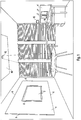
- Fig. 1 shows an example of a work space in the form of an office with a total of three embodiments of lighting and display devices according to the invention.
- Today's typical main activities in an office include concentrated work, telecommunications, video conferencing, meetings, etc.
- modern electronic media such as computers with Internet access etc. are used, which are generally becoming increasingly versatile and intuitive to use .
- the invention offers a particularly advantageous one Lighting and display devices (hereinafter also referred to as "device"), the possible use of the invention not being restricted to the environment of an office.
- a lighting and display device according to the invention can also be used in a private room area, in a hall or in principle also outdoors.
- a first embodiment of a device according to the invention is shown, which is also referred to below briefly as "video conference unit".
- the device comprises a display which is arranged on the relevant wall of the room and which has a first light-emitting surface 2 or “light-emitting surface 2 of the display”.
- a "light emitting surface” is a surface from which light can be actively emitted.
- the display is used to show information. It therefore represents a display device and can be connected, for example, to a conventional computer known per se in such a way that it accordingly serves as a display for this computer. Means known per se such as wireless mouse or keyboard units can be provided as an interface to the computer.
- the display can be, for example, a display device based on plasma technology or an LCD (Liquid Crystal Display).
- the screen diagonal of the display can be, for example, between 80 and 140 cm.
- a lighting element can be seen for illuminating an environment of the device, for example for illuminating the room.
- the light-emitting element has a second light-emitting surface 4 or a “light-emitting surface 4 of the light-emitting element”, which is larger than the first light-emitting surface 2. It can be provided that the light-emitting element is designed to generate a diffuse light.
- a matrix arrangement of LEDs can be provided as the light source. In this case, LEDs can be provided that can produce colored light, in short “colored” LEDs, for example “RGB LEDs” and / or LEDs that can generate white light, in short “white LEDs”.
- the second light-emitting surface 4 has an outer boundary 6, which is rectangular in the example shown.
- the mutual arrangement of the two light-emitting surfaces 2, 4 is such that the first light-emitting surface 2 is arranged in a central region with respect to the outer boundary 6 of the second light-emitting surface 4.
- the first Light-emitting surface 2 with respect to the outer boundary 6 of the second light-emitting surface 4 can be arranged in the center or “in the middle”.
- the device can be operated in two different modes, namely in a "lighting mode” and in a “display mode".
- the lighting mode the device is provided, at least primarily, for lighting an environment of the device, that is to say, for example, for lighting the room.
- the display mode the device is provided, at least primarily, for displaying information using the display on the first light-emitting surface 2.
- the device can be used to emit light for illumination not only via the light-emitting surface 4 of the lighting element, but also additionally via the light-emitting surface 2 of the display. Due to the above-mentioned type of relative arrangement of the two light-emitting surfaces 2, 4, the light-emitting surface 2 of the display is, as it were, integrated into the light-emitting surface 4 of the lighting element, so that overall a quasi-uniform appearing and in this sense enlarged light-emitting surface is available for illumination. In this way, the light emission options of the device and thus the lighting options are improved.
- the boundaries between the two functional units of the "lighting" device on the one hand and "display” on the other hand are, so to speak, "blurred" in the device according to the invention.
- the display in this mode the display supplements the lighting element, so that in the lighting mode the lighting element and the display form a functional unit; in this case, the display is "integrated" into the lighting element. In this sense, it forms an "integrative" part in the lighting mode. Therefore, the device as a whole is particularly space-saving.
- the second light-emitting surface 4 can be arranged in a ring, specifically in the form of a closed ring around the first light-emitting surface 2.
- the light-emitting surface 2 of the display can be arranged approximately at eye level with respect to a person sitting or standing in the room, so that information displayed on the first light-emitting surface 2 is generally easy and good can be seen, while the light-emitting surface 4 of the lighting element is clearly above and below Light emitting surface extends beyond the display.
- the outer boundary 6 of the second light-emitting surface 4 is between 30 cm and 100 cm above the upper boundary of the first light-emitting surface 2.
- the same can also be provided for the lower boundaries and the two corresponding lateral boundaries. With an overall comparatively large light emission surface, a comparatively pleasant light for lighting can be generated.
- the two light-emitting surfaces 2, 4 cover a predominant part of the relevant wall of the room.
- the lengths of the sides of the outer boundary 6 of the second light-emitting surface 4 can be in the range of meters, for example between one and five meters.
- the display can advantageously be designed to emit light in the same or in a similar color and / or in the same or in a similar brightness or intensity as the lighting element.
- "white light” of the same brightness or at least similar brightness can be emitted from both light emission surfaces 2, 4.
- illumination can be achieved in the illumination mode in which the light emission via the two light emission surfaces 2, 4 appears particularly homogeneous; overall, a particularly uniform "light image” can be produced in this way.
- “similar” color refers to a color that is located in an equally spaced color diagram within a small environment of the color of the light of the lighting element in question.
- a "similar" brightness or intensity is a brightness that deviates less than a small amount, for example less than 10%, from the relevant brightness or intensity of the light of the lighting element.
- the lighting element is advantageously designed to emit light of different colors and / or brightness in different areas of the second light emitting surface.
- it can be provided in the display mode that the lighting element can be controlled in such a way that light is emitted from the second light-emitting surface 4 in such a way that the contrast from the display on the first light-emitting surface 2 is reduced towards the outside.
- the control being able to be provided such that the display on the first light-emitting surface 2 is brightness and / or color outwards slowly decreasing "continued", namely under the lower resolution or pixel density of the lighting element compared to the display.
- the shortest distance between the first light-emitting surface 2 and the second light-emitting surface 4 is at most as large as half the diameter of the first light-emitting surface 2, preferably at most as large as one-tenth the diameter of the first light-emitting surface 2
- this distance is less than one tenth of the diameter of the first light-emitting surface 2 and is essentially only filled by a narrow frame 8, which can be part of the display and which surrounds the first light-emitting surface 2.
- the screen diagonal of the light-emitting surface 2 of the display is 110 cm; in this case, the diameter of the first light-emitting surface is 110 cm and a tenth of it is 11 cm, so that the space between the two light-emitting surfaces 2, 4 would have a width in this case that is less than 11 cm at any point.
- the device can furthermore have a camera (not shown in the figure), which is connected to a computer together with the display in such a way that a video conference can be carried out with it.
- the camera can be arranged, for example, in the area of the frame 8, for example embedded in the frame 8.
- the display is used for the display, for example for displaying information such as is typically shown on a display when working with a computer, a correspondingly high resolution or pixel density is provided for the display.
- the display is designed to be able to display or resolve more pixels per unit area than the lighting element, since information about the second light emitting surface 4 is not provided.
- the device as a whole can be designed with a large area in relation to a room, it is also particularly suitable for being arranged in front of a wall, as is the case in the example shown in front of the left wall. For this reason, it can also be particularly advantageous to arrange a material in front of the light source of the second light-emitting surface 4, that is to say for example in front of the corresponding LEDs, which is permeable to light, but has a damping effect with respect to acoustics or sound. On in this way the device can also provide acoustic insulation. For example, an acoustic panel made of transparent honeycomb material can be provided for this.
- the device can be designed to be particularly space-saving if the two light-emitting surfaces 2, 4 are arranged essentially in one plane and the total extent of the device perpendicular to this plane, that is to say its “strength” or “thickness”, is comparatively small.
- the first light-emitting surface 2 and the second light-emitting surface 4 are arranged between two parallel planes, the spacing of which is as large as half the diameter of the first light-emitting surface 2, preferably as large as a tenth of the diameter of the first light-emitting surface 2 can of course also be provided that the two light-emitting surfaces 2, 4 are arranged in one plane. This further promotes a particularly uniform appearance of the two light-emitting surfaces in the illumination mode.
- a control unit for controlling the display and the lighting element is also provided.
- the control unit is preferably designed to switch the two modes mentioned, ie the lighting mode and the display mode, on or off. It can preferably be provided that the light emitted by the first light-emitting surface 2 can be adjusted in terms of its brightness and color to the light that is emitted by the second light-emitting surface 4 with the control unit in the illumination mode, preferably in such a way that the light diffuses that emits from the first light emitting surface 2 differs as little as possible from the light emitted from the second light emitting surface 4. This facilitates the operation of the device when the lighting mode is set.
- a second exemplary embodiment of a lighting and display device according to the invention is shown on the right-hand side, which is also referred to below for short as an “office table unit”. Only differences from the first exemplary embodiment are discussed below. Unless otherwise stated, the explanations for the first exemplary embodiment apply analogously or analogously.
- the first light-emitting surface is composed of a plurality, in the example shown, of two separate segments 2 'and 2 ".
- the two segments 2 ', 2 " can each represent displays that are connected to a computer or each to a computer.
- the second light-emitting surface 4' is predominantly to the right and left of the two segments 2 ', 2" the first light emitting surface is arranged.
- the two segments 2 ', 2 " can, so to speak, be” embedded "in the second light-emitting surface 4'.
- the two light-emitting surfaces 2 ', 2" and 4' form a "light wall".
- the two light-emitting surfaces 2 ', 2 "and 4' are arranged essentially vertically, specifically on a rear boundary of a horizontal work surface 10, which can be an office table surface, for example.
- an additional light 12 can be provided in this case, with which the work surface 10 can be illuminated from above, so that an "accent lighting" can be generated.
- a lamp based on a mirror projector can be provided for this purpose.
- the mirror can be attached to the lighting element, for example in the area of the upper boundary of the second light-emitting surface 4 or the “light wall”.
- the mirror is pivotable and can be moved by a motor.
- a camera can also be attached to the mirror with which an image of the work surface 10 can be captured, so that an active tracking of the mirror with the aid of the motor is made possible on this basis.
- automatic focusing of the projection surface or work surface can be provided.
- the light which is emitted by the second light-emitting surface 4 ', is selected in intensity and color such that a contrast reduction between the first light-emitting surface or the two segments 2', 2 "of the first light-emitting surface and the Backlight is achieved.
- a further example of a lighting and display device can be seen, which is also briefly referred to below as "ceiling unit”.
- This has a projector (not visible in the figure as such) for projecting images, and a lighting element with a light-emitting surface 40.
- the projector can be, for example, a device usually referred to as a "video projector”.
- the light emitting surface 40 is oriented parallel to the ceiling, that is to say essentially horizontally.
- the projector is arranged so that it can be projected downwards.
- the explanations for the first exemplary embodiment also apply mutatis mutandis to this third exemplary embodiment.
- the device can be operated both in a "lighting mode” and in a "display mode”.
- the light emitting surface 40 corresponds to the light emitting surface 4 of the lighting element in the first exemplary embodiment; Unless otherwise shown, the light-emitting surface 40 can therefore have the same features as the second light-emitting surface 4 in the first exemplary embodiment. In particular, it can in turn be provided that LEDs are provided as light sources and that a translucent acoustic insulation is arranged in front of these LEDs in the direction of radiation.
- the light-emitting surface 40 has an opening 42.
- the projector is arranged relative to the lighting element in such a way that images can be projected downward through the opening 42 with the projector.
- the projector comprises an optical system which is arranged in the area of the opening 42 or in the opening 42. It can be provided that the projector is, so to speak, "embedded" in the lighting element or in the light-emitting surface 40 of the lighting element.
- a table with a table surface 50 is arranged below the device, so that the table surface 50 serves as a projection surface for the projector.
- the projector is designed to project an image which corresponds to a display such as can be shown on the light-emitting surface 2 of the display in the first exemplary embodiment.
- the projector can be connected to a computer.
- Means known per se, such as wireless mouse or keyboard units, can in turn be provided as an interface to the computer.
- the projector is designed to emit a uniform light in the illumination mode, so that the corresponding projection surface, in this case the table surface 50 or a partial area of the table surface 50, is illuminated uniformly.
- the projector can be used in lighting mode Take on the function of a spotlight.
- color-neutral white lighting can be provided for this.
- a corresponding tracking of the light cone is again possible, as has been shown above for the additional light 12 in the office table unit.
- the double function of the projector which serves as display means in the display mode and as the illumination means in the illumination mode, is particularly advantageous here.
- Fig. 1 shown combination of three lighting and display devices according to the invention is particularly suitable for use in an office environment.
- the "video conference unit” video conferences can be carried out.
- the "office table unit” is suitable for concentrated work and telecommunications and the "ceiling unit” for a meeting.
- the combination shown is particularly suitable for essential, typical main activities in the work environment of an office.
- a combination of two lighting and display devices according to the invention is of course also advantageous.
- the "video conference unit” can be combined with the "office table unit” and the same applies to the other possible sub-combinations.
- a common computer preferably with a USB connection, that is to say an “office PC”, can be provided, which can be connected to all the devices accordingly. If necessary, the mirror projector can also be adjusted using this computer.
Landscapes
- Engineering & Computer Science (AREA)
- Multimedia (AREA)
- Signal Processing (AREA)
- Devices For Indicating Variable Information By Combining Individual Elements (AREA)
- Control Of Indicators Other Than Cathode Ray Tubes (AREA)
Claims (11)
- Dispositif d'éclairage et d'affichage, qui est conçu pour fonctionner dans deux modes différents, à savoir dans un mode d'affichage et dans un mode d'éclairage,
comportant- un écran avec une première surface d'émission lumineuse (2), et- un élément lumineux avec une deuxième surface d'émission lumineuse (4),la surface d'émission lumineuse désignant une surface à partir de laquelle de la lumière peut être émise activement,
la première surface d'émission lumineuse (2) étant plus petite que la deuxième surface d'émission lumineuse (4) et étant en l'occurrence, par rapport à la délimitation (6) extérieure de la deuxième surface d'émission lumineuse (4), disposée dans une zone centrale, et en l'occurrence l'écran ainsi que le l'élément lumineux étant conçus pour représenter des pixels individuels sur la surface d'émission lumineuse (2, 4) respective, l'écran étant conçu pour représenter plus de pixels par unité de surface que l'élément lumineux,
le dispositif d'éclairage et d'affichage étant, dans le mode d'affichage, prévu au moins en premier lieu pour l'affichage d'informations à l'aide de l'écran sur la première surface d'émission lumineuse (2) et, dans le mode d'éclairage, au moins en premier lieu pour l'éclairage d'un environnement du dispositif d'éclairage et d'affichage,
de la lumière étant, dans le mode d'éclairage, émise non seulement par le biais de la surface d'émission lumineuse (4) de l'élément lumineux, mais en plus également par le biais de la surface d'émission lumineuse (2) de l'écran,
l'écran étant conçu pour émettre de la lumière dans la même couleur que, ou dans une couleur semblable à, et/ou dans la même luminosité que, ou dans une luminosité semblable à l'élément lumineux de sorte que, dans le mode d'éclairage, il est obtenu un éclairage avec lequel l'émission de lumière par le biais des deux surfaces d'émission lumineuse (2, 4) apparaît particulièrement homogène. - Dispositif d'éclairage et d'affichage selon la revendication 1,
dans lequel l'écran comporte des sources de lumière sous la forme de LED ou un affichage à cristaux liquides. - Dispositif d'éclairage et d'affichage selon l'une des revendications précédentes,
dans lequel l'élément lumineux comporte des sources de lumière sous la forme de LED. - Dispositif d'éclairage et d'affichage selon la revendication 3,
dans lequel un matériau destiné à l'isolation acoustique est disposé devant les LED de l'élément lumineux dans la direction de rayonnement. - Dispositif d'éclairage et d'affichage selon l'une des revendications précédentes,
dans lequel la distance la plus courte entre la première surface d'émission lumineuse (2) et la deuxième surface d'émission lumineuse (4) est au maximum égale au demi-diamètre de la première surface d'émission lumineuse (2), de préférence au maximum égale à un dixième du diamètre de la première surface d'émission lumineuse (2). - Dispositif d'éclairage et d'affichage selon l'une des revendications précédentes,
dans lequel la première surface d'émission lumineuse (2) et la deuxième surface d'émission lumineuse (4) sont disposées essentiellement à l'intérieur d'un plan, de préférence entre deux plans parallèles, dont l'intervalle est égal au demi-diamètre de la première surface d'émission lumineuse (2), de préférence égal à un dixième du diamètre de la première surface d'émission lumineuse (2). - Dispositif d'éclairage et d'affichage selon l'une des revendications précédentes,
comportant en outre une unité de commande destinée au pilotage de l'écran et de l'élément lumineux. - Combinaison de trois dispositifs d'éclairage et d'affichage, un premier dispositif d'éclairage et d'affichage présentant la combinaison de caractéristiques citée dans l'une des revendications 1 à 7, un deuxième dispositif d'éclairage et d'affichage présentant la combinaison de caractéristiques citée dans l'une des revendications 1 à 7, et un troisième dispositif d'éclairage et d'affichage comportant :- un projecteur destiné à la projection d'images, et- un élément lumineux avec une surface d'émission lumineuse (40),la surface d'émission lumineuse (40) comportant dans une zone centrale une ouverture (42), et le projecteur étant disposé relativement à l'élément lumineux de telle sorte que des images peuvent être projetées avec le projecteur à travers l'ouverture (42).
- Combinaison selon la revendication 8,
dans laquelle l'élément lumineux comporte des sources de lumière sous la forme de LED. - Combinaison selon la revendication 8 ou 9,
dans laquelle un matériau destiné à l'isolation acoustique est disposé devant les LED dans la direction de rayonnement. - Combinaison selon l'une des revendications 8 à 10,
dans laquelle le deuxième dispositif d'éclairage et d'affichage comporte une lampe supplémentaire destinée à l'éclairage d'une surface de travail (10) adjacente à la deuxième surface d'émission de lumineuse (4') du deuxième dispositif d'éclairage et d'affichage, et de préférence disposée essentiellement à angle droit par rapport à celui-ci.
Applications Claiming Priority (2)
| Application Number | Priority Date | Filing Date | Title |
|---|---|---|---|
| DE102008026517A DE102008026517A1 (de) | 2008-06-03 | 2008-06-03 | Beleuchtungs- und Anzeigevorrichtung |
| PCT/EP2009/003956 WO2009146893A1 (fr) | 2008-06-03 | 2009-06-03 | Dispositif d’éclairage et d’affichage |
Publications (2)
| Publication Number | Publication Date |
|---|---|
| EP2281397A1 EP2281397A1 (fr) | 2011-02-09 |
| EP2281397B1 true EP2281397B1 (fr) | 2020-05-27 |
Family
ID=41111372
Family Applications (1)
| Application Number | Title | Priority Date | Filing Date |
|---|---|---|---|
| EP09757276.2A Active EP2281397B1 (fr) | 2008-06-03 | 2009-06-03 | Dispositif d éclairage et d affichage |
Country Status (3)
| Country | Link |
|---|---|
| EP (1) | EP2281397B1 (fr) |
| DE (1) | DE102008026517A1 (fr) |
| WO (1) | WO2009146893A1 (fr) |
Families Citing this family (1)
| Publication number | Priority date | Publication date | Assignee | Title |
|---|---|---|---|---|
| CN106530990A (zh) * | 2016-12-27 | 2017-03-22 | 京东方科技集团股份有限公司 | 显示装置、显示系统 |
Citations (10)
| Publication number | Priority date | Publication date | Assignee | Title |
|---|---|---|---|---|
| JPH11144510A (ja) * | 1997-11-06 | 1999-05-28 | Matsushita Electric Ind Co Ltd | 照明装置 |
| US20020198438A1 (en) * | 2001-06-22 | 2002-12-26 | Virginia Tech Intellectual Properties, Inc. | Method and overhead system for performing a plurality of therapeutic functions within a room |
| US20030016236A1 (en) * | 2001-07-18 | 2003-01-23 | Barry Bronson | Immersive augmentation for display systems |
| US6611297B1 (en) * | 1998-04-13 | 2003-08-26 | Matsushita Electric Industrial Co., Ltd. | Illumination control method and illumination device |
| EP1379917A2 (fr) * | 2001-04-06 | 2004-01-14 | 3M Innovative Properties Company | Ecrans et procedes d'affichage d'informations |
| EP1396781A2 (fr) * | 2002-09-05 | 2004-03-10 | Sony Computer Entertainment Inc. | Système d'affichage, dispositif de commande d'affichage, dispositif d'affichage, procédé d'affichage et dispositif d'interface utilisateur |
| WO2005017739A1 (fr) * | 2003-08-19 | 2005-02-24 | Koninklijke Philips Electronics N.V. | Methode et appareil d'affichage de signaux a contenu visuel |
| WO2005057921A2 (fr) * | 2003-12-09 | 2005-06-23 | Reactrix Systems, Inc. | Systeme d'affichage video interactif autonome |
| US20070211475A1 (en) * | 2006-03-08 | 2007-09-13 | Laura Sevack | Light projector accessory for recessed lighting fixtures |
| WO2007113754A1 (fr) * | 2006-03-31 | 2007-10-11 | Koninklijke Philips Electronics N.V. | Rendu de contenu adaptatif basé sur des trames de contenu supplémentaires |
Family Cites Families (11)
| Publication number | Priority date | Publication date | Assignee | Title |
|---|---|---|---|---|
| DE19941541A1 (de) * | 1999-09-01 | 2001-03-15 | Kostal Leopold Gmbh & Co Kg | Elektrolumineszenz-Display |
| RU2159514C1 (ru) * | 1999-09-02 | 2000-11-20 | Немцова Светлана Рафаиловна | Способ формирования внешней подсветки при просмотре электронного изображения |
| JP4176299B2 (ja) * | 2000-09-29 | 2008-11-05 | 富士フイルム株式会社 | 医用画像表示システム |
| DE10260831B3 (de) * | 2002-12-23 | 2004-04-15 | Lisa Dräxlmaier GmbH | Beleuchtungssystem für Anzeigen in Fahrzeugen |
| EP1636986B1 (fr) * | 2003-06-12 | 2007-02-21 | Koninklijke Philips Electronics N.V. | Dispositif permettant simultanement de projeter des images et d'emettre une lumiere d'ambiance |
| EP1551178A1 (fr) * | 2003-12-18 | 2005-07-06 | Koninklijke Philips Electronics N.V. | Système supplémentaire d'affichage visuel |
| US7864204B2 (en) * | 2004-11-30 | 2011-01-04 | Koninklijke Philips Electronics N.V. | Display system |
| DE102005043310B4 (de) * | 2005-09-12 | 2007-10-04 | Siemens Ag | Anzeigesystem insbesondere für eine industrielle Automatisierungseinrichtung |
| US20070126864A1 (en) | 2005-12-05 | 2007-06-07 | Kiran Bhat | Synthesizing three-dimensional surround visual field |
| US8385707B2 (en) * | 2005-12-20 | 2013-02-26 | Tp Vision Holding B.V. | Layered light guide for producing ambient lighting |
| WO2007131334A1 (fr) | 2006-05-11 | 2007-11-22 | Imaginum Inc. | Module multi-pixel émetteur de lumière |
-
2008
- 2008-06-03 DE DE102008026517A patent/DE102008026517A1/de not_active Withdrawn
-
2009
- 2009-06-03 EP EP09757276.2A patent/EP2281397B1/fr active Active
- 2009-06-03 WO PCT/EP2009/003956 patent/WO2009146893A1/fr not_active Ceased
Patent Citations (10)
| Publication number | Priority date | Publication date | Assignee | Title |
|---|---|---|---|---|
| JPH11144510A (ja) * | 1997-11-06 | 1999-05-28 | Matsushita Electric Ind Co Ltd | 照明装置 |
| US6611297B1 (en) * | 1998-04-13 | 2003-08-26 | Matsushita Electric Industrial Co., Ltd. | Illumination control method and illumination device |
| EP1379917A2 (fr) * | 2001-04-06 | 2004-01-14 | 3M Innovative Properties Company | Ecrans et procedes d'affichage d'informations |
| US20020198438A1 (en) * | 2001-06-22 | 2002-12-26 | Virginia Tech Intellectual Properties, Inc. | Method and overhead system for performing a plurality of therapeutic functions within a room |
| US20030016236A1 (en) * | 2001-07-18 | 2003-01-23 | Barry Bronson | Immersive augmentation for display systems |
| EP1396781A2 (fr) * | 2002-09-05 | 2004-03-10 | Sony Computer Entertainment Inc. | Système d'affichage, dispositif de commande d'affichage, dispositif d'affichage, procédé d'affichage et dispositif d'interface utilisateur |
| WO2005017739A1 (fr) * | 2003-08-19 | 2005-02-24 | Koninklijke Philips Electronics N.V. | Methode et appareil d'affichage de signaux a contenu visuel |
| WO2005057921A2 (fr) * | 2003-12-09 | 2005-06-23 | Reactrix Systems, Inc. | Systeme d'affichage video interactif autonome |
| US20070211475A1 (en) * | 2006-03-08 | 2007-09-13 | Laura Sevack | Light projector accessory for recessed lighting fixtures |
| WO2007113754A1 (fr) * | 2006-03-31 | 2007-10-11 | Koninklijke Philips Electronics N.V. | Rendu de contenu adaptatif basé sur des trames de contenu supplémentaires |
Also Published As
| Publication number | Publication date |
|---|---|
| DE102008026517A1 (de) | 2009-12-10 |
| EP2281397A1 (fr) | 2011-02-09 |
| WO2009146893A1 (fr) | 2009-12-10 |
Similar Documents
| Publication | Publication Date | Title |
|---|---|---|
| EP3218795A2 (fr) | Dispositif d'affichage et son procédé de fonctionnement | |
| DE112013000581B4 (de) | Zweischirmanzeige und Anzeigeverfahren | |
| DE102005027261A1 (de) | Leuchte mit Hauptlichtquelle und Zusatzlichtquelle | |
| DE102018105569A1 (de) | Leuchteinrichtung | |
| EP3555521A1 (fr) | Dispositif d'éclairage | |
| EP2030190A1 (fr) | Dispositif d'affichage | |
| DE102015205003A1 (de) | Beleuchtungsvorrichtung | |
| DE102006055926A1 (de) | Anzeige mit über Kreuz angeordneten Leuchteinheiten | |
| EP1105769A1 (fr) | Systeme d'affichage en couleur a production sequentielle de couleurs primaires | |
| WO2009146893A1 (fr) | Dispositif d’éclairage et d’affichage | |
| DE10261657A1 (de) | Anordnung zur zwei-oder dreidimensionalen Darstellung | |
| DE102012206826A1 (de) | Projektionsvorrichtung | |
| DE102012011202A1 (de) | Projektor und Verfahren zum Erzeugen eines Bildes | |
| WO2013143567A1 (fr) | Module d'affichage pour un dispositif d'affichage | |
| DE202022100048U1 (de) | Sicherheitszeichenleuchte | |
| DE19702344A1 (de) | Beleuchtungsanordnung für Arbeitsplätze | |
| EP2466572B1 (fr) | Elément d'éclairage et agencement de plusieurs éléments d'éclairage pour la représentation d'images | |
| EP4080109B1 (fr) | Luminaire multifonction destiné à l'éclairage d'un poste de travail | |
| WO2004092775A2 (fr) | Dispositif de representation bidimensionnelle ou tridimensionnelle | |
| EP4130550A1 (fr) | Luminaire d'éclairage d'un poste de travail | |
| EP3289834A1 (fr) | Dispositif d'éclairage présentant plusieurs moyens d'éclairage pouvant être commandés individuellement | |
| DE102012108294A1 (de) | Beleuchtungsvorrichtung | |
| WO2008128636A2 (fr) | Système d'éclairage à répartition chromatique et/ou distribution de luminance variables | |
| AT16366U1 (de) | Verfahren und System zum Erzeugen von Lichtinszenierungen | |
| DE10317614A1 (de) | Anordnung zur zwei- oder dreidimensionalen Darstellung |
Legal Events
| Date | Code | Title | Description |
|---|---|---|---|
| PUAI | Public reference made under article 153(3) epc to a published international application that has entered the european phase |
Free format text: ORIGINAL CODE: 0009012 |
|
| 17P | Request for examination filed |
Effective date: 20101103 |
|
| AK | Designated contracting states |
Kind code of ref document: A1 Designated state(s): AT BE BG CH CY CZ DE DK EE ES FI FR GB GR HR HU IE IS IT LI LT LU LV MC MK MT NL NO PL PT RO SE SI SK TR |
|
| AX | Request for extension of the european patent |
Extension state: AL BA RS |
|
| DAX | Request for extension of the european patent (deleted) | ||
| STAA | Information on the status of an ep patent application or granted ep patent |
Free format text: STATUS: EXAMINATION IS IN PROGRESS |
|
| GRAP | Despatch of communication of intention to grant a patent |
Free format text: ORIGINAL CODE: EPIDOSNIGR1 |
|
| STAA | Information on the status of an ep patent application or granted ep patent |
Free format text: STATUS: GRANT OF PATENT IS INTENDED |
|
| INTG | Intention to grant announced |
Effective date: 20200220 |
|
| GRAS | Grant fee paid |
Free format text: ORIGINAL CODE: EPIDOSNIGR3 |
|
| GRAA | (expected) grant |
Free format text: ORIGINAL CODE: 0009210 |
|
| STAA | Information on the status of an ep patent application or granted ep patent |
Free format text: STATUS: THE PATENT HAS BEEN GRANTED |
|
| AK | Designated contracting states |
Kind code of ref document: B1 Designated state(s): AT BE BG CH CY CZ DE DK EE ES FI FR GB GR HR HU IE IS IT LI LT LU LV MC MK MT NL NO PL PT RO SE SI SK TR |
|
| REG | Reference to a national code |
Ref country code: GB Ref legal event code: FG4D Free format text: NOT ENGLISH |
|
| REG | Reference to a national code |
Ref country code: CH Ref legal event code: EP |
|
| REG | Reference to a national code |
Ref country code: AT Ref legal event code: REF Ref document number: 1275800 Country of ref document: AT Kind code of ref document: T Effective date: 20200615 |
|
| REG | Reference to a national code |
Ref country code: DE Ref legal event code: R096 Ref document number: 502009016204 Country of ref document: DE |
|
| PGFP | Annual fee paid to national office [announced via postgrant information from national office to epo] |
Ref country code: AT Payment date: 20200622 Year of fee payment: 12 |
|
| REG | Reference to a national code |
Ref country code: LT Ref legal event code: MG4D |
|
| PG25 | Lapsed in a contracting state [announced via postgrant information from national office to epo] |
Ref country code: SE Free format text: LAPSE BECAUSE OF FAILURE TO SUBMIT A TRANSLATION OF THE DESCRIPTION OR TO PAY THE FEE WITHIN THE PRESCRIBED TIME-LIMIT Effective date: 20200527 Ref country code: IS Free format text: LAPSE BECAUSE OF FAILURE TO SUBMIT A TRANSLATION OF THE DESCRIPTION OR TO PAY THE FEE WITHIN THE PRESCRIBED TIME-LIMIT Effective date: 20200927 Ref country code: LT Free format text: LAPSE BECAUSE OF FAILURE TO SUBMIT A TRANSLATION OF THE DESCRIPTION OR TO PAY THE FEE WITHIN THE PRESCRIBED TIME-LIMIT Effective date: 20200527 Ref country code: FI Free format text: LAPSE BECAUSE OF FAILURE TO SUBMIT A TRANSLATION OF THE DESCRIPTION OR TO PAY THE FEE WITHIN THE PRESCRIBED TIME-LIMIT Effective date: 20200527 Ref country code: GR Free format text: LAPSE BECAUSE OF FAILURE TO SUBMIT A TRANSLATION OF THE DESCRIPTION OR TO PAY THE FEE WITHIN THE PRESCRIBED TIME-LIMIT Effective date: 20200828 Ref country code: NO Free format text: LAPSE BECAUSE OF FAILURE TO SUBMIT A TRANSLATION OF THE DESCRIPTION OR TO PAY THE FEE WITHIN THE PRESCRIBED TIME-LIMIT Effective date: 20200827 Ref country code: PT Free format text: LAPSE BECAUSE OF FAILURE TO SUBMIT A TRANSLATION OF THE DESCRIPTION OR TO PAY THE FEE WITHIN THE PRESCRIBED TIME-LIMIT Effective date: 20200928 |
|
| REG | Reference to a national code |
Ref country code: NL Ref legal event code: MP Effective date: 20200527 |
|
| PG25 | Lapsed in a contracting state [announced via postgrant information from national office to epo] |
Ref country code: HR Free format text: LAPSE BECAUSE OF FAILURE TO SUBMIT A TRANSLATION OF THE DESCRIPTION OR TO PAY THE FEE WITHIN THE PRESCRIBED TIME-LIMIT Effective date: 20200527 Ref country code: LV Free format text: LAPSE BECAUSE OF FAILURE TO SUBMIT A TRANSLATION OF THE DESCRIPTION OR TO PAY THE FEE WITHIN THE PRESCRIBED TIME-LIMIT Effective date: 20200527 Ref country code: BG Free format text: LAPSE BECAUSE OF FAILURE TO SUBMIT A TRANSLATION OF THE DESCRIPTION OR TO PAY THE FEE WITHIN THE PRESCRIBED TIME-LIMIT Effective date: 20200827 |
|
| PG25 | Lapsed in a contracting state [announced via postgrant information from national office to epo] |
Ref country code: NL Free format text: LAPSE BECAUSE OF FAILURE TO SUBMIT A TRANSLATION OF THE DESCRIPTION OR TO PAY THE FEE WITHIN THE PRESCRIBED TIME-LIMIT Effective date: 20200527 |
|
| PG25 | Lapsed in a contracting state [announced via postgrant information from national office to epo] |
Ref country code: DK Free format text: LAPSE BECAUSE OF FAILURE TO SUBMIT A TRANSLATION OF THE DESCRIPTION OR TO PAY THE FEE WITHIN THE PRESCRIBED TIME-LIMIT Effective date: 20200527 Ref country code: ES Free format text: LAPSE BECAUSE OF FAILURE TO SUBMIT A TRANSLATION OF THE DESCRIPTION OR TO PAY THE FEE WITHIN THE PRESCRIBED TIME-LIMIT Effective date: 20200527 Ref country code: RO Free format text: LAPSE BECAUSE OF FAILURE TO SUBMIT A TRANSLATION OF THE DESCRIPTION OR TO PAY THE FEE WITHIN THE PRESCRIBED TIME-LIMIT Effective date: 20200527 Ref country code: EE Free format text: LAPSE BECAUSE OF FAILURE TO SUBMIT A TRANSLATION OF THE DESCRIPTION OR TO PAY THE FEE WITHIN THE PRESCRIBED TIME-LIMIT Effective date: 20200527 Ref country code: CZ Free format text: LAPSE BECAUSE OF FAILURE TO SUBMIT A TRANSLATION OF THE DESCRIPTION OR TO PAY THE FEE WITHIN THE PRESCRIBED TIME-LIMIT Effective date: 20200527 Ref country code: IT Free format text: LAPSE BECAUSE OF FAILURE TO SUBMIT A TRANSLATION OF THE DESCRIPTION OR TO PAY THE FEE WITHIN THE PRESCRIBED TIME-LIMIT Effective date: 20200527 |
|
| REG | Reference to a national code |
Ref country code: CH Ref legal event code: PL |
|
| PG25 | Lapsed in a contracting state [announced via postgrant information from national office to epo] |
Ref country code: MC Free format text: LAPSE BECAUSE OF FAILURE TO SUBMIT A TRANSLATION OF THE DESCRIPTION OR TO PAY THE FEE WITHIN THE PRESCRIBED TIME-LIMIT Effective date: 20200527 Ref country code: SK Free format text: LAPSE BECAUSE OF FAILURE TO SUBMIT A TRANSLATION OF THE DESCRIPTION OR TO PAY THE FEE WITHIN THE PRESCRIBED TIME-LIMIT Effective date: 20200527 Ref country code: PL Free format text: LAPSE BECAUSE OF FAILURE TO SUBMIT A TRANSLATION OF THE DESCRIPTION OR TO PAY THE FEE WITHIN THE PRESCRIBED TIME-LIMIT Effective date: 20200527 |
|
| REG | Reference to a national code |
Ref country code: DE Ref legal event code: R097 Ref document number: 502009016204 Country of ref document: DE |
|
| PG25 | Lapsed in a contracting state [announced via postgrant information from national office to epo] |
Ref country code: LU Free format text: LAPSE BECAUSE OF NON-PAYMENT OF DUE FEES Effective date: 20200603 |
|
| PLBE | No opposition filed within time limit |
Free format text: ORIGINAL CODE: 0009261 |
|
| STAA | Information on the status of an ep patent application or granted ep patent |
Free format text: STATUS: NO OPPOSITION FILED WITHIN TIME LIMIT |
|
| REG | Reference to a national code |
Ref country code: BE Ref legal event code: MM Effective date: 20200630 |
|
| PG25 | Lapsed in a contracting state [announced via postgrant information from national office to epo] |
Ref country code: CH Free format text: LAPSE BECAUSE OF NON-PAYMENT OF DUE FEES Effective date: 20200630 Ref country code: IE Free format text: LAPSE BECAUSE OF NON-PAYMENT OF DUE FEES Effective date: 20200603 Ref country code: LI Free format text: LAPSE BECAUSE OF NON-PAYMENT OF DUE FEES Effective date: 20200630 |
|
| 26N | No opposition filed |
Effective date: 20210302 |
|
| PG25 | Lapsed in a contracting state [announced via postgrant information from national office to epo] |
Ref country code: SI Free format text: LAPSE BECAUSE OF FAILURE TO SUBMIT A TRANSLATION OF THE DESCRIPTION OR TO PAY THE FEE WITHIN THE PRESCRIBED TIME-LIMIT Effective date: 20200527 Ref country code: BE Free format text: LAPSE BECAUSE OF NON-PAYMENT OF DUE FEES Effective date: 20200630 |
|
| REG | Reference to a national code |
Ref country code: AT Ref legal event code: MM01 Ref document number: 1275800 Country of ref document: AT Kind code of ref document: T Effective date: 20210603 |
|
| PG25 | Lapsed in a contracting state [announced via postgrant information from national office to epo] |
Ref country code: AT Free format text: LAPSE BECAUSE OF NON-PAYMENT OF DUE FEES Effective date: 20210603 |
|
| REG | Reference to a national code |
Ref country code: DE Ref legal event code: R084 Ref document number: 502009016204 Country of ref document: DE |
|
| PG25 | Lapsed in a contracting state [announced via postgrant information from national office to epo] |
Ref country code: TR Free format text: LAPSE BECAUSE OF FAILURE TO SUBMIT A TRANSLATION OF THE DESCRIPTION OR TO PAY THE FEE WITHIN THE PRESCRIBED TIME-LIMIT Effective date: 20200527 Ref country code: MT Free format text: LAPSE BECAUSE OF FAILURE TO SUBMIT A TRANSLATION OF THE DESCRIPTION OR TO PAY THE FEE WITHIN THE PRESCRIBED TIME-LIMIT Effective date: 20200527 Ref country code: CY Free format text: LAPSE BECAUSE OF FAILURE TO SUBMIT A TRANSLATION OF THE DESCRIPTION OR TO PAY THE FEE WITHIN THE PRESCRIBED TIME-LIMIT Effective date: 20200527 |
|
| PG25 | Lapsed in a contracting state [announced via postgrant information from national office to epo] |
Ref country code: MK Free format text: LAPSE BECAUSE OF FAILURE TO SUBMIT A TRANSLATION OF THE DESCRIPTION OR TO PAY THE FEE WITHIN THE PRESCRIBED TIME-LIMIT Effective date: 20200527 |
|
| PGFP | Annual fee paid to national office [announced via postgrant information from national office to epo] |
Ref country code: GB Payment date: 20220621 Year of fee payment: 14 |
|
| PGFP | Annual fee paid to national office [announced via postgrant information from national office to epo] |
Ref country code: FR Payment date: 20220623 Year of fee payment: 14 |
|
| P01 | Opt-out of the competence of the unified patent court (upc) registered |
Effective date: 20230530 |
|
| PGFP | Annual fee paid to national office [announced via postgrant information from national office to epo] |
Ref country code: DE Payment date: 20230627 Year of fee payment: 15 |
|
| GBPC | Gb: european patent ceased through non-payment of renewal fee |
Effective date: 20230603 |
|
| PG25 | Lapsed in a contracting state [announced via postgrant information from national office to epo] |
Ref country code: GB Free format text: LAPSE BECAUSE OF NON-PAYMENT OF DUE FEES Effective date: 20230603 |
|
| PG25 | Lapsed in a contracting state [announced via postgrant information from national office to epo] |
Ref country code: FR Free format text: LAPSE BECAUSE OF NON-PAYMENT OF DUE FEES Effective date: 20230630 |
|
| REG | Reference to a national code |
Ref country code: DE Ref legal event code: R119 Ref document number: 502009016204 Country of ref document: DE |
|
| PG25 | Lapsed in a contracting state [announced via postgrant information from national office to epo] |
Ref country code: DE Free format text: LAPSE BECAUSE OF NON-PAYMENT OF DUE FEES Effective date: 20250101 |