EP2281426B1 - Machine d'ensemencement et/ou fertilisante et procédé pour déterminer le débit d'une telle machine - Google Patents
Machine d'ensemencement et/ou fertilisante et procédé pour déterminer le débit d'une telle machine Download PDFInfo
- Publication number
- EP2281426B1 EP2281426B1 EP10171073A EP10171073A EP2281426B1 EP 2281426 B1 EP2281426 B1 EP 2281426B1 EP 10171073 A EP10171073 A EP 10171073A EP 10171073 A EP10171073 A EP 10171073A EP 2281426 B1 EP2281426 B1 EP 2281426B1
- Authority
- EP
- European Patent Office
- Prior art keywords
- sensor
- mass flow
- rate
- metering
- seeding
- Prior art date
- Legal status (The legal status is an assumption and is not a legal conclusion. Google has not performed a legal analysis and makes no representation as to the accuracy of the status listed.)
- Active
Links
Images


Classifications
-
- A—HUMAN NECESSITIES
- A01—AGRICULTURE; FORESTRY; ANIMAL HUSBANDRY; HUNTING; TRAPPING; FISHING
- A01C—PLANTING; SOWING; FERTILISING
- A01C7/00—Sowing
- A01C7/08—Broadcast seeders; Seeders depositing seeds in rows
- A01C7/081—Seeders depositing seeds in rows using pneumatic means
-
- A—HUMAN NECESSITIES
- A01—AGRICULTURE; FORESTRY; ANIMAL HUSBANDRY; HUNTING; TRAPPING; FISHING
- A01C—PLANTING; SOWING; FERTILISING
- A01C7/00—Sowing
- A01C7/08—Broadcast seeders; Seeders depositing seeds in rows
- A01C7/10—Devices for adjusting the seed-box ; Regulation of machines for depositing quantities at intervals
- A01C7/102—Regulating or controlling the seed rate
- A01C7/105—Seed sensors
-
- A—HUMAN NECESSITIES
- A01—AGRICULTURE; FORESTRY; ANIMAL HUSBANDRY; HUNTING; TRAPPING; FISHING
- A01C—PLANTING; SOWING; FERTILISING
- A01C7/00—Sowing
- A01C7/08—Broadcast seeders; Seeders depositing seeds in rows
- A01C7/10—Devices for adjusting the seed-box ; Regulation of machines for depositing quantities at intervals
- A01C7/107—Calibration of the seed rate
-
- Y—GENERAL TAGGING OF NEW TECHNOLOGICAL DEVELOPMENTS; GENERAL TAGGING OF CROSS-SECTIONAL TECHNOLOGIES SPANNING OVER SEVERAL SECTIONS OF THE IPC; TECHNICAL SUBJECTS COVERED BY FORMER USPC CROSS-REFERENCE ART COLLECTIONS [XRACs] AND DIGESTS
- Y02—TECHNOLOGIES OR APPLICATIONS FOR MITIGATION OR ADAPTATION AGAINST CLIMATE CHANGE
- Y02P—CLIMATE CHANGE MITIGATION TECHNOLOGIES IN THE PRODUCTION OR PROCESSING OF GOODS
- Y02P60/00—Technologies relating to agriculture, livestock or agroalimentary industries
Definitions
- the present invention relates to a seeding and/or fertilizing machine and to a method of determining flow in such a machine.
- the machine comprises a tank of particulate material, a material metering structure and an air delivery system for conveying the material from the tank to the ground.
- Air Seeding machines include a metering device which regulates that amount of seed and fertilizer that is dispensed into an air stream.
- the air stream conveys the seed and/or fertilizer to a secondary tower which divides the flow of materials into individual row air streams for delivery to furrows made in soil by a furrow opener.
- the current technology metering devices meter the seed or granular fertilizer on a volumetric basis.
- US6093926 provides another type of seeding machine comprising a tank of particulate material, a material metering structure and an air delivery system for conveying the material from the tank to the ground, wherein the machine comprising a flow determining device, wherein said flow determining device including a first sensor located in the air delivery system for providing a first signal, a second sensor located in the air delivery system and a processor connected to the first sensor for determining a particulate material mass flow signal in dependence on the sensor signal.
- the metering device In order to achieve an acceptable degree of metering accuracy, the metering device must be calibrated in accordance with the density of the material being metered.
- the calibration procedure which typically includes a manual weighing step, can be time consuming and, depending upon the skill level of the operator, can be inaccurate and result in reduced productivity.
- only one of the materials be metered at a time during the calibration procedure and presents added difficulties when attempting to provide a calibration system that can operate on-the-go.
- one object of the invention is to overcome the above mentioned problems.
- a seeding and/or fertilizing machine of the above mentioned type includes a flow determining device, wherein said flow determining device comprising a first sensor located in the air delivery system for providing a first signal indicative of the force of the particulate material impacting the first sensor; a second sensor located in the air delivery system for providing an interference signal indicative of one or more variables that negatively impact first sensor accuracy; and a processor connected to the first and second sensors for determining a particulate material mass flow signal in dependence on the impact sensor signal and the interference signal.
- a mass flow rate sensor is placed in the air stream of an air seeder or similar implement that conveys materials such as seed and fertilizer.
- the mass flow rate sensor reduces calibration delays and provides more accurate seeding and fertilizing rates, even when the seed and fertilizer are combined into one air stream.
- a mass flow rate sensor is located in the secondary tower used to divide the seed and/or fertilizer flow into individual rows.
- the metered materials bounce off of the sensor, change direction and then flow into the individual row air streams.
- the sensor provides a signal indicative of the force of the material against the sensor which is dependent mainly on material mass and velocity.
- a processor calculates mass flow rate from the force signal.
- the processor also receives at least one additional signal indicative of unwanted noise and/or interference or other variable that can adversely affect the calculated mass flow rate.
- the additional signal is utilized to provide a correction signal and calculate a more accurate mass flow rate. Factors such as air velocity variations, implement vibration, air flow induced vibrations, air pressure drop, and differential pressure variation can be detected by one or more transducers connected to the processor.
- an air flow velocity sensor can be utilized since the air velocity affects the velocity of the seed/fertilizer in the secondary tower and the impact force against the mass flow sensor.
- the air flow velocity signal is utilized to provide a correction of the force sensor signal to compensate for air velocity and more accurately reflect mass flow.
- a single mass sensor or multiple sensors up to the number of secondary towers can be used. If the number of sensor is less than the number of secondary towers, one sensor acts as a proxy for other secondary towers.
- Some implement configurations result in seed and fertilizer being mixed in the same air stream and in the secondary tower.
- the processor employs a software algorithm to temporarily increase the metering rate of one of the materials. The change in mass flow rate is then calculated. Using the mass flow rate change and the meter speed change, a calibration factor is determined from which the approximate rate of the individual materials can be calculated. The procedure allows on-the-go calibration of multiple meters and can provide such calibration without the need to completely stop one of the materials if so desired.
- sensor structure can be mounted below each meter to provide separate information relevant to seed and fertilizer mass flow.
- the additional mass flow sensor structure provides signals for compensating for and/or confirming the accuracy of the first mass flow sensor and allows more accurate on-the-go calibration of multiple meters. Many factors influence flow measuring accuracy, and providing the additional sensor structure at a different location than that of the first sensor can improve operation significantly.
- the processor can negate the detrimental effects of air flow and/or pressure variations, vibrations and various other extraneous factors.
- a vibration sensor is connected to the impact plate of the mass sensor. During brief interruptions of material flow from the metering device, average vibration signals from the air flow and implement movement can be determined by the processor, and these signals can be subtracted from the total mass flow sensor signal generated when material flows in the system to provide a more accurate indication of mass flow.
- Additional mass flow sensor structure can include an intrusive mass flow sensor such as a centripetal force or Coriolis sensor, or a non-intrusive sensor such as an optical sensor can be used. In certain conditions, such sensors can be used independently to achieve the desired accuracies. In more difficult detection environments, the additional mass flow sensor structure can be placed under the metering devices for compensating for and/or confirming the accuracy of the mass flow sensor.
- an intrusive mass flow sensor such as a centripetal force or Coriolis sensor
- a non-intrusive sensor such as an optical sensor can be used.
- the additional mass flow sensor structure can be placed under the metering devices for compensating for and/or confirming the accuracy of the mass flow sensor.
- a closed loop control system utilizes the mass flow rate to adjust the metering rate for achieving desired flow rate.
- a method of accurately providing the flow rate includes the following steps:
- a seeding and fertilizing implement 10 including tanks 12 and 14 for containing materials to be distributed to the soil.
- the tanks 12 and 14 are mounted on a frame 16 supported by ground wheels 18 for forward movement over the ground by a towing vehicle (not shown) connected to a forward hitch 20.
- a ground-engaging implement 24 includes a frame 26 supported by ground wheels 28 and connected to the rear of the frame 16 by a hitch 30.
- An air delivery system 34 includes a fan 36 connected to the frame 16 and directing air rearwardly through material delivery conduit structure 38.
- Material metering structure 40 delivers the materials from the tanks 12 and 14 through meter outputs 42 and 44, e.g. venturi structures, into the material delivery conduit structure 38. The material is then carried rearwardly in the air stream to secondary distribution towers 50.
- Each tower 50 includes an uppermost distributing head 52 located at the uppermost end of a vertical distribution tube 54. The head 52 evenly divides the flow of material into a number of secondary distribution lines 58.
- Each distribution line 58 delivers material to a furrow formed by one of a plurality of openers 60 attached to the frame 26 at transversely spaced locations, and a trailing firming or closing wheel 62 associated with each opener 60 firms the soil over the material deposited in the furrow.
- the material metering structure 40 includes variable speed meter drives 72 and 74 ( Figure 2 ) connected to material metering structures 76 and 78 located in the bottom of the tanks 12 and 14. As the drives 72 and 74 rotate the metering structures 76 and 78, materials from the tanks 12 and 14 are delivered via venturi 42 and venturi 44 into the conduit structure 38 which, in turn, conveys the materials to the distribution tower 50.
- a feed rate controller 80 connected to the variable speed meter drives 72 and 74 receives a speed signal at an input 82 indicative of implement ground speed and adjusts the meter drive speeds to maintain a selected flow rate with changing ground speed.
- An input device 86 is connected to the controller 80 for entering a desired material mass flow rate and for setting the metering structure 40 at a nominal mass flow rate.
- the device 86 can include a GPS-based system or other automated system to provide desired metering rates to a processor 90.
- the processor 90 provides rate control inputs to the controller 80 at 92 and 94.
- An operator and/or, and the feed rate controller utilizes the speed signal and the inputs from the processor 90 to adjust the drives 72 and 74 to maintain the desired flow rates.
- a mass flow rate sensor 100 is located in the secondary distribution tower 50 used to divide the seed and/or fertilizer flow into individual rows. The metered materials bounce off of the sensor 100 and change direction. The individual row air streams in the conduits 58 then deliver the material to the furrow.
- the sensor 100 provides a signal at an input to the processor 90 indicative of the force of the material against the sensor which is dependent on material mass.
- the processor 90 calculates mass flow rate from the force signal received at the input 102.
- the processor 90 also receives one or more additional signals at inputs 104 and 106 indicative of unwanted noise and/or interference or other variable that can adversely affect the calculated mass flow rate.
- the processor 90 utilizes the additional signal or signals at the inputs 104 and 106 to provide a correction signal and calculate a more accurate mass flow rate.
- additional flow indication signals can be provided by meter output sensor structure 108 located upstream of the first sensor 100 and including outputs 110 connected to an input of the processor 90.
- the sensor structure 110 includes flow sensors located at the outputs of the metering structures 76 and 78.
- the input 104 is connected to a vibration sensor 114 mounted on or in close proximity to the impact sensor 100.
- a vibration sensor 114 mounted on or in close proximity to the impact sensor 100.
- average vibration signals from the air flow and implement movement can be determined by the processor 90 from the signal at the input 104.
- the average vibration signals are then subtracted from the total mass flow sensor signal generated when material flows in the system so that a more accurate indication of mass flow is achieved.
- an air sensor 116 placed in a non-interfering location in the upright tube 54 provides an air signal to the input 106.
- the sensor 116 can provide an air velocity and/or air pressure indications to the processor 90.
- the air velocity in the tube 54 affects the velocity of the material or materials in the secondary tower 50 which, in turn, affects the impact force against the mass flow sensor 100.
- the velocity signal at the input 106 is utilized to provide a correction of the force sensor signal at the input 102 to compensate for air velocity and more accurately reflect mass flow.
- the signal from the sensor 116 can also be utilized to compensate for other atmospheric-related variations such as varying air pressure at the distribution head 52.
- a single sensor 100 or multiple sensors 100 up to the number of secondary towers can be used. If the number of sensor is less than the number of secondary towers, one sensor acts as a proxy for other secondary distribution towers 50.
- the processor 90 employs a software algorithm to temporarily increase the metering rate of one of the materials by changing the speed of one of the drives 72 and 74. The processor 90 then calculates the change in mass flow rate resulting from the speed change. Using the mass flow rate change and the meter speed change, the processor 90 calculates a calibration factor from which the approximate rate of the individual materials can be calculated. The procedure allows on-the-go calibration of multiple meters and can provide such calibration without the need to completely stop one of the materials if so desired.
- the processor can negate the detrimental effects of air flow and/or pressure variations, vibrations and various other extraneous factors.
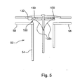
- a vibration sensor 120 ( Figure 5 ) is connected to the sensor 100.
- average vibration signals from the air flow and implement movement can be determined by the processor 90.
- the processor 90 subtracts the average vibration signals from the total mass flow sensor signal generated by the sensor 100 to provide a more accurate indication of mass flow.
- the sensor 100 includes a washer-type of load cell 130 connected to a larger washer-shaped impact plate 132 at the top of the upright tube 54.
- the diameter of the impact plate 132 is approximately equal to the diameter of the tube 54 so that substantially all the material delivered through the tube 54 impacts the plate before exiting through the distribution lines 58.
- the impact plate 132 is shown as flat, other surface shapes may also be used including curved and/or cone-shaped surfaces (see the broken lines at 132c of Figure 5 ) that can help to more evenly distribute the materials to the lines 58.
- the processor 90 begins the calibration routine at 138 ( Figure 3 ) and initializes the mass flow sensor 100 at 140.
- the processor 90 then calculates a mass flow rate at 142 from the signals from the various detectors.
- the calculated flow rate is then compared with a preset desired flow rate at 144. If the calculated flow rate matches the preset rate, the calibration cycle is ended at 146 for a preselected period of time after which the calibration cycle is restarted. If the flow rate does not match the desired flow rate, the speeds of the metering drives 72 and 74 are varied at 148 and the mass flow rate is recalculated at 150 until the flow rate matches the desired rate at 144.
- the processor 90 employs a software algorithm shown schematically at Figure 4 to temporarily increase the metering rate of one commodity by changing the speed of one of the drives 72 and 74. A new mass flow rate is then calculated from which the processor 90 determines the mass flow rates of the individual materials from the bins 12 and 14. Relative meter speeds are then adjusted as necessary to provide the overall metering rate with the proper individual material rates.
- the calibration routine is started at 158, and the mass flow sensor 100 is initialized at 160.
- a mass flow rate of the combined materials from the tanks 12 and 14 is calculated at 162, and the flow rate is compared to a preselected number at 164. If the overall flow rate is not within the selected range, the meter rate is adjusted at 168 and recalculated at 170 until the overall rate is within the desired range. Once the flow rate is determined at 164 to be within the desired range, the meter speed for one of the commodity meters 76 and 78 is temporarily increased at 174 and a new mass flow rate is determined at 176.
- the change in the mass flow rate occasioned by the known meter speed change of one of the commodities at 174 should provide a given change in mass flow rate.
- the new mass flow rate is compared at 180 to a newly determined flow rate number that is dependent upon the meter speed change at 174. If the flow rate change does not match the flow rate change calculated by the processor 90 for the given increase in speed of one of the commodity meters at 174, the meter rate for that meter is adjusted at 182 and mass flow rate again is calculated at 184 after the adjustment until the calculated flow rate matches determined flow rate number dependent on the meter speed change.
- the processor 90 causes the over-speed condition established at 174 to cease and returns control to the algorithm of Figure 3 .
- the processor 90 initiates the calibration routine of Figure 4 to assure the desired ratios of materials are delivered to the soil.
- the calibration routine can be initiated for changing conditions, such as for meter speed changes that occur, for example, when ground speed has to be varied with changing field conditions.
- a closed loop control system utilizes the mass flow rate to adjust the metering rate for achieving desired flow rate.
- a method of accurately providing the flow rate includes the following steps:
Landscapes
- Life Sciences & Earth Sciences (AREA)
- Soil Sciences (AREA)
- Environmental Sciences (AREA)
- Fertilizing (AREA)
- Sowing (AREA)
- Measuring Volume Flow (AREA)
Claims (17)
- Machine d'ensemencement et/ou fertilisante (10) comprenant un réservoir (12, 14) de matériau particulaire, une structure de dosage des matériaux (40) et un système d'amenée d'air (34) pour acheminer le matériau du réservoir (12, 14) vers le sol, caractérisée en ce qu'elle comprend un dispositif de détermination de débit, où ledit dispositif de détermination de débit comprend :un premier capteur (100) situé dans le système d'amenée d'air (34) pour délivrer un premier signal indicatif de la force du matériau particulaire frappant le premier capteur (100) ;un second capteur (114, 116) situé dans le système d'amenée d'air (34) pour délivrer un signal d'interférence indicatif d'une ou plusieurs variables qui affectent la précision du premier capteur ; etun processeur (90) connecté aux premier et second capteurs (100, 114, 116) pour déterminer un signal de débit massique de matériau particulaire en fonction du signal du capteur d'impact et du signal d'interférence.
- Machine d'ensemencement et/ou fertilisante (10) selon la revendication 1, dans laquelle le premier capteur (100) comprend un capteur d'impact délivrant un signal d'impact, où le premier capteur (100) est situé dans une tête diviseur (52) d'une tour de distribution (50).
- Machine d'ensemencement et/ou fertilisante (10) selon la revendication 2, dans laquelle le second capteur (114, 116) comprend un capteur de vibration.
- Machine d'ensemencement et/ou fertilisante (10) selon l'une des revendications 1 à 3, dans laquelle le second capteur (114, 116) délivre un signal d'interférence indicatif d'une variable, la variable comprenant au moins un paramètre parmi les suivantes :le débit d'air, la chute de pression d'air, les vibrations et la variation de pression différentielle.
- Machine d'ensemencement et/ou fertilisante (10) selon l'une des revendications 1 à 4, dans laquelle le dispositif de détermination de débit comprend un troisième capteur (108) pour délivrer une indication au processeur sur le débit massique du matériau A (débit massique A) délivré par la structure de dosage de matériau (76, 78) au système d'amenée d'air (34), où la structure de dosage délivre également un matériau B au système d'amenée d'air (34), et où le processeur (90) réagit au premier signal pour délivrer une indication de débit massique totale du débit massique du matériau A et du matériau B.
- Machine d'ensemencement et/ou fertilisante (10) selon l'une des revendications 1 à 5, dans laquelle le processeur (90) réagit au premier signal et à un changement du taux de dosage de l'un des deux matériaux pour déterminer un débit massique de matériau individuel.
- Machine d'ensemencement et/ou fertilisante (10) selon l'une des revendications 1 à 6, dans laquelle le dispositif de détermination de débit comprend un contrôleur de débit (80) pour ajuster le taux d'amenée de deux matériaux particulaires, le processeur (90) réagit au changement du premier signal et à l'ajustement du débit pour déterminer le débit massique des matériaux particulaires individuels.
- Machine d'ensemencement et/ou fertilisante (10) selon l'une des revendications 1 à 7, dans laquelle le dispositif de détermination de débit comprend un contrôleur de débit (80) pour faire fonctionner la structure de dosage (40) à un débit massique nominal
dans un cycle d'étalonnage à l'aide d'une valeur d'étalonnage standard approximative comprenant un dispositif d'entrée (86) pour entrer un débit massique de matériau souhaité et pour paramétrer le dispositif de dosage au débit massique nominal, où le processeur (90) réagit aux informations du cycle d'étalonnage pour affiner la valeur d'étalonnage et le contrôleur (80) réajuste le taux de dosage à un taux de dosage précis. - Machine d'ensemencement et/ou fertilisante (10) selon l'une des revendications 2 à 8, dans laquelle le capteur d'impact comprend une surface non plane pour faciliter la distribution des matériaux de manière uniforme depuis la tête diviseur (52) vers des lignes de distribution (58).
- Machine d'ensemencement et/ou fertilisante (10) selon l'une des revendications 5 à 9, dans laquelle le troisième capteur (108) comprend un capteur de débit des semences et le débit massique A comprend un débit des semences, où le débit massique B comprend un débit des produits chimiques, où le processeur (90) délivre des indications séparées sur le débit des semences et le débit des produits chimiques.
- Procédé de détermination de débit dans une machine d'ensemencement et/ou fertilisante (10) qui comprend un réservoir (12, 14) de matériau particulaire, une structure de dosage (40) et un système d'amenée d'air (34) comprenant une tour de distribution verticale (50) pour acheminer le matériau dosé du réservoir (12, 14) vers le sol, le procédé comprenant les étapes suivantes :positionner un premier capteur (100) dans la tour de distribution (50) ;délivrer un premier signal (102) indicatif de la force du matériau particulaire frappant le premier capteur (100) ;positionner un second capteur (114, 116) dans le système d'amenée d'air (34) ;délivrer un signal d'interférence (104, 106) indicatif d'une ou plusieurs variables qui affectent la précision du premier capteur à l'aide du second capteur (114, 116) ; etdéterminer un débit massique de matériau particulaire en fonction du signal du capteur d'impact (102) et du signal d'interférence (104, 106).
- Procédé selon la revendication 11, dans lequel l'étape comprenant de positionner le premier capteur (100) comprend de positionner un capteur d'impact au niveau de la partie la plus haute de la tour de distribution verticale (50) ou au niveau d'une tête diviseur (52) de la tour de distribution (50).
- Procédé selon la revendication 11 ou la revendication 12, dans lequel l'étape comprenant de positionner un second capteur (114, 116) dans le système d'amenée d'air (34) comprend de positionner un capteur de vibration de manière adjacente au premier capteur (100) ou de positionner un capteur d'air dans le système d'amenée d'air (34).
- Procédé tel que décrit dans l'une des revendications 11 à 13, comprenant les étapes supplémentaires suivantes :a. entrer un débit massique souhaité pour au moins deux matériaux dans un dispositif de contrôle de débit (80) ;b. paramétrer la structure de dosage (40) pour délivrer un débit massique nominal ;c. mettre en oeuvre un cycle d'étalonnage ; etd. utiliser des informations du cycle d'étalonnage pour ajuster le taux de dosage à un taux souhaité.
- Procédé tel que décrit dans l'une des revendications 11 à 14, comprenant les étapes supplémentaires suivantes :a. mesurer deux matériaux différents simultanément à travers la tour de distribution (50) ;b. changer le taux de dosage de l'un des deux matériaux différents ;c. déterminer à partir d'au moins le premier signal (102), un nouveau débit massique de matériau particulaire ; etd. à partir du nouveau débit massique de matériau particulaire, calculer le débit massique individuel d'au moins un des deux matériaux différents.
- Procédé tel que décrit dans l'une des revendications 11 à 15, comprenant de fournir un troisième capteur (108) adjacent à la structure de dosage (40) en amont de la tour de distribution (50), où l'étape comprenant de fournir le troisième capteur (108) comprend de positionner une structure de détection au niveau des sorties de mesure (42, 44).
- Procédé tel que décrit dans l'une des revendications 11 à 15, comprenant de fournir un troisième capteur (108) adjacent à la structure de dosage (40) en amont de la tour de distribution et comprenant l'étape comprenant de mesurer simultanément la semence et les produits chimiques dans le système d'amenée d'air (34), où l'étape comprenant de fournir le troisième capteur (108) comprend de fournir un capteur de semence, et comprenant l'étape comprenant de déterminer un taux de dosage individuel d'au moins un signal parmi les signaux de la semence et des produits chimiques provenant du troisième capteur (108) et du premier capteur (100).
Applications Claiming Priority (1)
| Application Number | Priority Date | Filing Date | Title |
|---|---|---|---|
| US12/535,986 US8504310B2 (en) | 2009-08-05 | 2009-08-05 | Particulate flow sensing for an agricultural implement |
Publications (3)
| Publication Number | Publication Date |
|---|---|
| EP2281426A2 EP2281426A2 (fr) | 2011-02-09 |
| EP2281426A3 EP2281426A3 (fr) | 2011-07-06 |
| EP2281426B1 true EP2281426B1 (fr) | 2012-12-26 |
Family
ID=43216762
Family Applications (1)
| Application Number | Title | Priority Date | Filing Date |
|---|---|---|---|
| EP10171073A Active EP2281426B1 (fr) | 2009-08-05 | 2010-07-28 | Machine d'ensemencement et/ou fertilisante et procédé pour déterminer le débit d'une telle machine |
Country Status (7)
| Country | Link |
|---|---|
| US (1) | US8504310B2 (fr) |
| EP (1) | EP2281426B1 (fr) |
| AR (1) | AR077711A1 (fr) |
| CA (1) | CA2710718C (fr) |
| ES (1) | ES2401864T3 (fr) |
| RU (1) | RU2536051C2 (fr) |
| UA (1) | UA104583C2 (fr) |
Cited By (2)
| Publication number | Priority date | Publication date | Assignee | Title |
|---|---|---|---|---|
| EP2932818A1 (fr) * | 2014-04-16 | 2015-10-21 | Horsch Maschinen GmbH | Dispositif d'épandage et procédé d'extraction du produit à épandre sous forme de granulés |
| CN115191181A (zh) * | 2016-07-13 | 2022-10-18 | 艾姆瓦克香港有限公司 | 利用种子运输机构电脉冲式排出带种子的农用产品的系统 |
Families Citing this family (72)
| Publication number | Priority date | Publication date | Assignee | Title |
|---|---|---|---|---|
| US8843281B2 (en) * | 2010-09-17 | 2014-09-23 | Kinze Manufacturing, Inc. | Seed characteristic sensor |
| US8671857B2 (en) | 2011-03-10 | 2014-03-18 | Cnh Canada, Ltd. | Variable geometry meter roller |
| US8656848B2 (en) | 2011-06-10 | 2014-02-25 | Great Plains Manufacturing, Inc. | Seed distribution tower for an air seeder |
| CA2838810C (fr) * | 2011-06-10 | 2017-08-01 | Great Plains Manufacturing, Incorporated | Tour de distribution de graines pour un semoir pneumatique |
| US8955445B2 (en) | 2012-05-31 | 2015-02-17 | Great Plains Manufacturing, Inc. | Seed distribution tower with modular components |
| US8746158B2 (en) | 2011-09-09 | 2014-06-10 | Cnh Industrial Canada, Ltd. | System and method for measuring product flow to an agricultural implement |
| US8869718B2 (en) | 2011-09-09 | 2014-10-28 | Cnh Industrial Canada, Ltd. | System and method for controlling product flow to an agricultural implement |
| EP3259972B1 (fr) * | 2012-07-25 | 2021-12-08 | Precision Planting LLC | Système et procédé de commande et de surveillance d'un engin agricole multirangs |
| NL1039764C2 (en) * | 2012-08-17 | 2014-02-18 | J O A Technology Beheer B V | A method of, a control system, a device, a sensor and a computer program product for controlling transport of fibrous material in a transport line of a pneumatic conveying system. |
| SE536827C2 (sv) * | 2012-12-18 | 2014-09-23 | Väderstad Verken Ab | Förfarande för styrning av lantbruksredskap samt lantbruksredskap |
| US9820431B2 (en) | 2013-08-27 | 2017-11-21 | American Vanguard Corporation | System and process for dispensing multiple and low rate agricultural products |
| US10470356B2 (en) | 2013-08-27 | 2019-11-12 | Amvac Chemical Corporation | System and method for dispensing multiple low rate agricultural products |
| US10064327B2 (en) | 2015-07-03 | 2018-09-04 | Amvac Chemical Corporation | Apparatus and method for minimizing the volume of a liquid carrier used for delivering agricultural products into a furrow during planting |
| US10517206B2 (en) | 2013-08-27 | 2019-12-31 | Amvac Chemical Corporation | System for providing prescriptive application of multiple products |
| US11026362B2 (en) | 2013-08-27 | 2021-06-08 | Amvac Chemical Corporation | System and method for treating individual seeds with liquid chemicals during the planting process |
| US11058046B2 (en) | 2013-08-27 | 2021-07-13 | Amvac Chemical Corporation | System and method for dispensing multiple low rate agricultural products |
| BR102013027318B1 (pt) | 2013-10-23 | 2019-12-10 | José Roberto do Amaral Assy | processo e dispositivo para controle de falhas na dosagem de sementes em plantadeiras |
| US9738200B2 (en) * | 2014-06-11 | 2017-08-22 | Cnh Industrial Canada, Ltd. | Air conveying system for filling of air seeder tank |
| US10123524B2 (en) * | 2014-06-19 | 2018-11-13 | Cnh Industrial Canada, Ltd. | Active system for optimization and plugging avoidance of seed/fertilizer in transport conducts |
| US9958301B2 (en) | 2014-07-11 | 2018-05-01 | Clemson University | Impact mass flow sensor for monitoring peanut harvest yields |
| US9950876B2 (en) * | 2014-09-26 | 2018-04-24 | Cnh Industrial Canada, Ltd. | Downward elbow with cyclonic effect and product overflow capability |
| CA2904783C (fr) * | 2014-11-04 | 2020-07-14 | Cnh Industrial Canada, Ltd. | Regulateur de pression de reservoir pour chariots a air |
| CA2905336C (fr) | 2014-11-04 | 2020-01-14 | Cnh Industrial Canada, Ltd. | Dispositif d'echappement de reservoir auxiliaire pour un mecanisme de distribution de produit agricole |
| CA2904294C (fr) | 2014-11-04 | 2019-11-12 | Cnh Industrial Canada, Ltd. | Reservoir de semences secondaire pour mecanisme de chariot a air |
| CA2904756C (fr) | 2014-11-04 | 2020-01-07 | Cnh Industrial Canada, Ltd. | Rouleaux doseurs a controle independant et systeme et methode de composantes de transport a air |
| CA2904778C (fr) | 2014-11-04 | 2020-03-10 | Cnh Industrial Canada, Ltd. | Systeme et methode d'etalonnage independant de rouleaux doseurs |
| US9615506B2 (en) * | 2014-11-10 | 2017-04-11 | Cnh Industrial Canada, Ltd. | System for monitoring and controlling product distribution in an agricultural system |
| US9888622B2 (en) | 2014-12-08 | 2018-02-13 | Cnh Industrial Canada, Ltd. | Air flow control of a distribution head for agricultural products |
| CA2911939C (fr) * | 2014-12-16 | 2019-08-20 | Cnh Industrial Canada, Ltd. | Modele de debit semi-empirique et methode de calibration pour des zones de debit non exploitees, dans un semoir pneumatique |
| US9781878B2 (en) * | 2015-01-20 | 2017-10-10 | Montag Investments, LLC | Metering system with variable discharge |
| US10194579B2 (en) | 2015-01-29 | 2019-02-05 | Cnh Industrial Canada, Ltd. | Sectional control calibration system and method |
| DE102015105769A1 (de) * | 2015-04-15 | 2016-10-20 | Lemken Gmbh & Co. Kg | Mehrfachvereinzelungseinrichtung |
| DE102015105790A1 (de) * | 2015-04-15 | 2016-10-20 | Lemken Gmbh & Co. Kg | Landwirtschaftliche Einzelkornsämaschine |
| US10188025B2 (en) | 2015-07-14 | 2019-01-29 | Clemson University Research Foundation | Yield monitor for windrow-collected materials |
| US9968027B2 (en) | 2015-07-14 | 2018-05-15 | Clemson University | Automated control systems and methods for underground crop harvesters |
| US9814173B2 (en) * | 2015-09-30 | 2017-11-14 | Deere & Company | Seeding system |
| US10246274B2 (en) * | 2015-11-04 | 2019-04-02 | Cnh Industrial Canada, Ltd. | Systems and methods for air cart pressurization monitoring |
| SE539925C2 (sv) * | 2016-05-23 | 2018-01-16 | Vaederstad Holding Ab | Förfarande för kalibrering av matningstakt hos en utmatningsanordning, en utmatningsanordning samt ett lantbruksredskap försett med en sådan utmatningsanordning |
| US20170355534A1 (en) * | 2016-06-13 | 2017-12-14 | Baker Hughes Incorporated | Dry bulk pneumatic metering assembly and method |
| IT201600069428A1 (it) * | 2016-07-04 | 2018-01-04 | Anulli Monica | Impianto per la distribuzione pneumatica di prodotti. |
| WO2018010012A1 (fr) * | 2016-07-12 | 2018-01-18 | Salford Group Inc. | Appareil et procédé de distribution de matériau particulaire |
| CA2977467C (fr) | 2016-10-11 | 2026-01-13 | Deere & Company | Mecanisme de semoir |
| RU2765500C2 (ru) * | 2017-05-05 | 2022-01-31 | Пресижн Плэнтинг Ллк | Система управления для вентиляционной системы пневматической сеялки |
| US10575459B2 (en) | 2017-07-03 | 2020-03-03 | Cnh Industrial Canada, Ltd. | Product distribution control system for an agricultural system |
| DE102017117973A1 (de) * | 2017-08-08 | 2019-02-14 | Amazonen-Werke H. Dreyer Gmbh & Co. Kg | Verfahren und System zum Dosieren von Saatgut in einer Sämaschine |
| US10609858B2 (en) | 2017-09-21 | 2020-04-07 | Deere & Company | Commodity metering system for work vehicle and calibration method for same |
| US11191207B2 (en) * | 2017-09-21 | 2021-12-07 | Deere & Company | Commodity metering system for work vehicle and calibration method for same |
| US11054292B2 (en) | 2018-01-02 | 2021-07-06 | Intelligent Agricultural Solutions Llc | Material flow monitoring system and method |
| US10942053B2 (en) | 2018-05-14 | 2021-03-09 | Deere & Company | Seeding system |
| RO135186A2 (ro) * | 2018-08-10 | 2021-09-30 | Great Plains Manufacturing,Inc. | Sistem de reglare a fluxului de seminţe |
| USD908277S1 (en) | 2018-08-25 | 2021-01-19 | Amvac Chemical Corporation | Container for dry products |
| MX2021002427A (es) | 2018-08-28 | 2021-07-15 | Amvac Hong Kong Ltd | Sistema de contenedores para el transporte y dispensacion de productos agricolas. |
| US11382261B2 (en) | 2018-08-28 | 2022-07-12 | Amvac Chemical Corporation | System and method for stacking containers |
| US10820484B2 (en) | 2018-09-07 | 2020-11-03 | Cnh Industrial Canada, Ltd. | Air cart product flow condition monitoring |
| US11215601B2 (en) | 2018-10-25 | 2022-01-04 | Cnh Industrial Canada, Ltd. | System for monitoring soil conditions based on acoustic data and associated methods for adjusting operating parameters of a seed-planting implement based on monitored soil conditions |
| US11109527B2 (en) | 2018-12-28 | 2021-09-07 | Cnh Industrial Canada, Ltd. | Flow control for agricultural implement pneumatic system |
| US11464154B2 (en) | 2019-01-31 | 2022-10-11 | Cnh Industrial Canada, Ltd. | Multi-product sensing system for a common conduit of an agricultural product distribution system |
| US11154004B2 (en) * | 2019-04-26 | 2021-10-26 | Deere & Company | Agricultural seed sensing and control system |
| ES3063720T3 (en) * | 2019-05-31 | 2026-04-20 | Prec Planting Llc | Methods and systems for using duty cycle of sensors to determine seed or particle flow rate |
| CA3047567C (fr) * | 2019-06-25 | 2021-07-13 | Bourgault Industries Ltd. | Doseurs de produits montes sur un cadre d`outil |
| CA3097708A1 (en) | 2019-11-14 | 2021-05-14 | Cnh Industrial Canada, Ltd. | Particulate material metering system for an agricultural implement |
| US11765991B2 (en) | 2019-11-14 | 2023-09-26 | Cnh Industrial Canada, Ltd. | Particulate material metering system for an agricultural implement |
| CN111357436A (zh) * | 2020-02-28 | 2020-07-03 | 山东省农业机械科学研究院 | 一种气吸式铺膜播种机气路系统及气吸式铺膜播种机 |
| SE544903C2 (en) * | 2020-03-10 | 2022-12-27 | Vaederstad Holding Ab | An agricultural implement, a computer program, a computer-readable medium and a method for detecting abnormal product flow in such an agricultural implement |
| CN111869390B (zh) * | 2020-08-03 | 2021-12-17 | 杭州市临安区农林技术推广中心 | 一种农作物化肥定额施肥方法 |
| US12349614B2 (en) | 2021-11-10 | 2025-07-08 | Deere & Company | Air seeding turn compensation using yaw rate from sensor on towing vehicle |
| US12584780B2 (en) | 2022-04-04 | 2026-03-24 | Deere & Company | Methods, systems, and apparatuses for bulk material meter calibration |
| US12623863B2 (en) * | 2023-02-21 | 2026-05-12 | Deere & Company | Automatically detecting or estimating material delivery delays and machine control |
| US12329056B2 (en) | 2023-05-25 | 2025-06-17 | Cnh Industrial Canada, Ltd. | Air flow control system for an agricultural system |
| US12599056B2 (en) | 2023-05-25 | 2026-04-14 | Cnh Industrial Canada, Ltd. | Air flow calibration system for an agricultural system |
| US12568874B2 (en) | 2023-05-25 | 2026-03-10 | Cnh Industrial Canada, Ltd. | Plug detection system for an agricultural system |
| WO2025043305A1 (fr) * | 2023-08-25 | 2025-03-06 | Assy Jose Roberto Do Amaral | Dispositif de surveillance d'intrants au moyen de capteurs pour une machine agricole |
Family Cites Families (39)
| Publication number | Priority date | Publication date | Assignee | Title |
|---|---|---|---|---|
| GB1235856A (en) * | 1967-09-06 | 1971-06-16 | Nat Res Dev | Improvements in or relating to the measurement of the flow of a particulate material |
| US3730395A (en) * | 1971-07-21 | 1973-05-01 | D Gallogly | Seed and fertilizer spreader |
| FR2157092A5 (fr) * | 1971-10-18 | 1973-06-01 | Commissariat Energie Atomique | |
| US4000398A (en) * | 1973-11-12 | 1976-12-28 | Conner Industrials, Inc. | Method and apparatus for analyzing harvester efficiency |
| US4079362A (en) * | 1976-07-02 | 1978-03-14 | Canadian Patents And Development Limited | Piezo-electric seed-flow monitor |
| US4280419A (en) * | 1977-03-21 | 1981-07-28 | International Harvester Company | Pneumatic system for conveying granular material |
| US4238790A (en) * | 1978-07-19 | 1980-12-09 | Mazogazdasagi Gepkiserleti Intezet | Sowing monitoring arrangement |
| US4401909A (en) * | 1981-04-03 | 1983-08-30 | Dickey-John Corporation | Grain sensor using a piezoelectric element |
| US4719805A (en) * | 1983-12-12 | 1988-01-19 | Beta Raven Inc. | Dry flow sensor with automatic speed compensation and totalizer circuit |
| DE3419884A1 (de) * | 1984-05-28 | 1985-11-28 | Amazonen-Werke H. Dreyer Gmbh & Co Kg, 4507 Hasbergen | Verfahren und vorrichtung zum akustischen zaehlen von partikeln |
| EP0380504A4 (en) * | 1987-08-04 | 1991-01-09 | Peter Adam Reuter | Flow line weighing device |
| DE3874325T2 (de) * | 1988-04-26 | 1993-02-25 | Ford New Holland Inc | Prall-detektoren. |
| US5177470A (en) * | 1990-08-06 | 1993-01-05 | Vansco Electronic Ltd. | Sensor device for particles in an air stream |
| US5343761A (en) * | 1991-06-17 | 1994-09-06 | Allen Myers | Method and apparatus for measuring grain mass flow rate in harvesters |
| EP0531141B1 (fr) * | 1991-09-04 | 1995-03-22 | Toyota Jidosha Kabushiki Kaisha | Système de coussin hydraulique pour une presse, ayant une vanne d'arrêt pour déconnecter les boulons de pression d'alimentation hydraulique lors du contact de l'outil mobile avec la pièce |
| RU2043006C1 (ru) * | 1992-07-20 | 1995-09-10 | Ленинградский сельскохозяйственный институт | Устройство контроля и управления расходом семян пневматической сеялкой |
| GB2296712B (en) * | 1995-01-05 | 1999-02-24 | British Gas Plc | Absorbents for separating nitrogen from a feed gas |
| US5598794A (en) * | 1995-02-13 | 1997-02-04 | Fluid Power Industries, Inc. | High accuracy automatically controlled variable linear seed spacing planting apparatus |
| US5650609A (en) * | 1995-05-15 | 1997-07-22 | Phoenix International Corporation | Seed monitoring system for counting seeds as they are dispensed through a seed planting tube |
| US6093926A (en) * | 1995-05-15 | 2000-07-25 | Deere & Company | Method of counting seeds dispensed through seed tubes of an air seeding system |
| US7254518B2 (en) * | 1996-03-28 | 2007-08-07 | Rosemount Inc. | Pressure transmitter with diagnostics |
| US5831539A (en) * | 1997-05-14 | 1998-11-03 | Deere & Company | Air seeder blockage monitoring system |
| US5831542A (en) * | 1997-05-14 | 1998-11-03 | Deere & Company | Air seeder blockage monitoring system |
| US5923262A (en) * | 1997-10-07 | 1999-07-13 | Deere & Company | Adaptive methods of determining blockage in an air seeder blockage monitoring system |
| EP0958726B1 (fr) * | 1998-05-22 | 2003-11-12 | Flexi-Coil Ltd. | Contrôle de l'air distributeur dans un semoir pneumatique |
| EP0997064B8 (fr) * | 1998-10-30 | 2004-07-14 | CNH Canada Ltd. | Dispositif de démarrage pour machines de distribution de produits agricoles |
| US6367336B1 (en) * | 1998-12-29 | 2002-04-09 | Hugo Gabriel Martina | Process mass flow apparatus and method for measuring the mass flow of powdered and granulated solids as well as the accumulated weight of material passed during a specified time |
| US6213690B1 (en) * | 1999-03-30 | 2001-04-10 | Deere & Company | Distribution manifold for air seeder |
| US6192813B1 (en) * | 1999-05-21 | 2001-02-27 | Flexi-Coil Ltd. | Apparatus for controlling the flow rate of an air seeder |
| US6661514B1 (en) * | 2000-02-17 | 2003-12-09 | Vansco Electronics Ltd. | Tube blockage monitor |
| US6516676B1 (en) * | 2000-03-29 | 2003-02-11 | Robert Lee Mullowney, Jr. | Airborne emissions monitoring probe |
| US6505569B1 (en) * | 2001-07-09 | 2003-01-14 | Leroy J. Richard | Seeder airflow control system |
| US6644225B2 (en) * | 2002-01-17 | 2003-11-11 | Deere & Company | Electronically controlled tuning orifice for seed meter tuning |
| US6584920B1 (en) * | 2002-09-17 | 2003-07-01 | Bourgault Industries Ltd. | System and method for adjusting air flow in air seeding applications |
| US6820459B2 (en) * | 2002-09-18 | 2004-11-23 | Deere & Company | Automatic mass-flow sensor calibration for a yield monitor |
| DE102004003702A1 (de) * | 2004-01-24 | 2005-08-11 | Amazonen-Werke H. Dreyer Gmbh & Co. Kg | Elektronische Vorrichtung zum Zählen kleiner Körperchen |
| US7182029B2 (en) * | 2004-08-25 | 2007-02-27 | Cnh America Llc | Inductor assembly for a product conveyance system |
| EP1744031B1 (fr) | 2005-07-14 | 2008-10-15 | Delphi Technologies, Inc. | Method pour corriger un signal de detection |
| DE102006038865A1 (de) * | 2006-08-18 | 2008-02-21 | Alois Pöttinger Maschinenfabrik Gmbh | Sämaschine sowie Verfahren zur Regelung des Austrags einer Sämaschine |
-
2009
- 2009-08-05 US US12/535,986 patent/US8504310B2/en active Active
-
2010
- 2010-07-21 CA CA2710718A patent/CA2710718C/fr active Active
- 2010-07-28 EP EP10171073A patent/EP2281426B1/fr active Active
- 2010-07-28 ES ES10171073T patent/ES2401864T3/es active Active
- 2010-08-04 AR ARP100102867A patent/AR077711A1/es active IP Right Grant
- 2010-08-04 UA UAA201009722A patent/UA104583C2/uk unknown
- 2010-08-04 RU RU2010132836/13A patent/RU2536051C2/ru not_active IP Right Cessation
Cited By (2)
| Publication number | Priority date | Publication date | Assignee | Title |
|---|---|---|---|---|
| EP2932818A1 (fr) * | 2014-04-16 | 2015-10-21 | Horsch Maschinen GmbH | Dispositif d'épandage et procédé d'extraction du produit à épandre sous forme de granulés |
| CN115191181A (zh) * | 2016-07-13 | 2022-10-18 | 艾姆瓦克香港有限公司 | 利用种子运输机构电脉冲式排出带种子的农用产品的系统 |
Also Published As
| Publication number | Publication date |
|---|---|
| EP2281426A3 (fr) | 2011-07-06 |
| ES2401864T3 (es) | 2013-04-25 |
| RU2010132836A (ru) | 2012-02-10 |
| AU2010202295B2 (en) | 2016-03-31 |
| US20110035163A1 (en) | 2011-02-10 |
| UA104583C2 (uk) | 2014-02-25 |
| CA2710718A1 (fr) | 2011-02-05 |
| EP2281426A2 (fr) | 2011-02-09 |
| RU2536051C2 (ru) | 2014-12-20 |
| AU2010202295A1 (en) | 2011-02-24 |
| US8504310B2 (en) | 2013-08-06 |
| CA2710718C (fr) | 2018-03-20 |
| AR077711A1 (es) | 2011-09-14 |
Similar Documents
| Publication | Publication Date | Title |
|---|---|---|
| CA2710718C (fr) | Debitmetre de matieres particulaires pour un instrument agricole | |
| US9043949B2 (en) | System and method of calibrating the meter of a product distribution machine | |
| EP2417846B1 (fr) | Procédé de fonctionnement d'un appareil de distribution | |
| EP2409558B1 (fr) | Appareil de distribution de produits et procédé de contrôle de celui-ci | |
| AU2012216679B2 (en) | System and method for measuring product flow to an agricultural implement | |
| AU2012216677B2 (en) | System and method for controlling product flow to an agricultural implement | |
| EP3150041B1 (fr) | Système de semis | |
| US9488512B2 (en) | Semi-empirical mass flow model and calibration method for undeveloped flow regions in an air seeder | |
| EP3462828B1 (fr) | Procédé de calibration du débit d'un dispositif de dosage et dispositif de dosage | |
| CA3007174A1 (fr) | Auto-etalonnage d'un semoir au moyen de balances de reservoir equipees d'une alarme de debit automatique |
Legal Events
| Date | Code | Title | Description |
|---|---|---|---|
| PUAI | Public reference made under article 153(3) epc to a published international application that has entered the european phase |
Free format text: ORIGINAL CODE: 0009012 |
|
| AK | Designated contracting states |
Kind code of ref document: A2 Designated state(s): AL AT BE BG CH CY CZ DE DK EE ES FI FR GB GR HR HU IE IS IT LI LT LU LV MC MK MT NL NO PL PT RO SE SI SK SM TR |
|
| AX | Request for extension of the european patent |
Extension state: BA ME RS |
|
| PUAL | Search report despatched |
Free format text: ORIGINAL CODE: 0009013 |
|
| AK | Designated contracting states |
Kind code of ref document: A3 Designated state(s): AL AT BE BG CH CY CZ DE DK EE ES FI FR GB GR HR HU IE IS IT LI LT LU LV MC MK MT NL NO PL PT RO SE SI SK SM TR |
|
| AX | Request for extension of the european patent |
Extension state: BA ME RS |
|
| 17P | Request for examination filed |
Effective date: 20120109 |
|
| GRAP | Despatch of communication of intention to grant a patent |
Free format text: ORIGINAL CODE: EPIDOSNIGR1 |
|
| GRAS | Grant fee paid |
Free format text: ORIGINAL CODE: EPIDOSNIGR3 |
|
| GRAA | (expected) grant |
Free format text: ORIGINAL CODE: 0009210 |
|
| AK | Designated contracting states |
Kind code of ref document: B1 Designated state(s): AL AT BE BG CH CY CZ DE DK EE ES FI FR GB GR HR HU IE IS IT LI LT LU LV MC MK MT NL NO PL PT RO SE SI SK SM TR |
|
| REG | Reference to a national code |
Ref country code: GB Ref legal event code: FG4D |
|
| REG | Reference to a national code |
Ref country code: CH Ref legal event code: EP |
|
| REG | Reference to a national code |
Ref country code: AT Ref legal event code: REF Ref document number: 589962 Country of ref document: AT Kind code of ref document: T Effective date: 20130115 |
|
| REG | Reference to a national code |
Ref country code: DE Ref legal event code: R096 Ref document number: 602010004282 Country of ref document: DE Effective date: 20130307 |
|
| REG | Reference to a national code |
Ref country code: ES Ref legal event code: FG2A Ref document number: 2401864 Country of ref document: ES Kind code of ref document: T3 Effective date: 20130425 |
|
| PG25 | Lapsed in a contracting state [announced via postgrant information from national office to epo] |
Ref country code: HR Free format text: LAPSE BECAUSE OF FAILURE TO SUBMIT A TRANSLATION OF THE DESCRIPTION OR TO PAY THE FEE WITHIN THE PRESCRIBED TIME-LIMIT Effective date: 20121226 Ref country code: FI Free format text: LAPSE BECAUSE OF FAILURE TO SUBMIT A TRANSLATION OF THE DESCRIPTION OR TO PAY THE FEE WITHIN THE PRESCRIBED TIME-LIMIT Effective date: 20121226 Ref country code: SE Free format text: LAPSE BECAUSE OF FAILURE TO SUBMIT A TRANSLATION OF THE DESCRIPTION OR TO PAY THE FEE WITHIN THE PRESCRIBED TIME-LIMIT Effective date: 20121226 Ref country code: LT Free format text: LAPSE BECAUSE OF FAILURE TO SUBMIT A TRANSLATION OF THE DESCRIPTION OR TO PAY THE FEE WITHIN THE PRESCRIBED TIME-LIMIT Effective date: 20121226 Ref country code: NO Free format text: LAPSE BECAUSE OF FAILURE TO SUBMIT A TRANSLATION OF THE DESCRIPTION OR TO PAY THE FEE WITHIN THE PRESCRIBED TIME-LIMIT Effective date: 20130326 |
|
| REG | Reference to a national code |
Ref country code: AT Ref legal event code: MK05 Ref document number: 589962 Country of ref document: AT Kind code of ref document: T Effective date: 20121226 |
|
| REG | Reference to a national code |
Ref country code: LT Ref legal event code: MG4D |
|
| REG | Reference to a national code |
Ref country code: NL Ref legal event code: VDEP Effective date: 20121226 |
|
| PG25 | Lapsed in a contracting state [announced via postgrant information from national office to epo] |
Ref country code: LV Free format text: LAPSE BECAUSE OF FAILURE TO SUBMIT A TRANSLATION OF THE DESCRIPTION OR TO PAY THE FEE WITHIN THE PRESCRIBED TIME-LIMIT Effective date: 20121226 Ref country code: SI Free format text: LAPSE BECAUSE OF FAILURE TO SUBMIT A TRANSLATION OF THE DESCRIPTION OR TO PAY THE FEE WITHIN THE PRESCRIBED TIME-LIMIT Effective date: 20121226 Ref country code: GR Free format text: LAPSE BECAUSE OF FAILURE TO SUBMIT A TRANSLATION OF THE DESCRIPTION OR TO PAY THE FEE WITHIN THE PRESCRIBED TIME-LIMIT Effective date: 20130327 |
|
| PG25 | Lapsed in a contracting state [announced via postgrant information from national office to epo] |
Ref country code: BE Free format text: LAPSE BECAUSE OF FAILURE TO SUBMIT A TRANSLATION OF THE DESCRIPTION OR TO PAY THE FEE WITHIN THE PRESCRIBED TIME-LIMIT Effective date: 20121226 Ref country code: CZ Free format text: LAPSE BECAUSE OF FAILURE TO SUBMIT A TRANSLATION OF THE DESCRIPTION OR TO PAY THE FEE WITHIN THE PRESCRIBED TIME-LIMIT Effective date: 20121226 Ref country code: AT Free format text: LAPSE BECAUSE OF FAILURE TO SUBMIT A TRANSLATION OF THE DESCRIPTION OR TO PAY THE FEE WITHIN THE PRESCRIBED TIME-LIMIT Effective date: 20121226 Ref country code: SK Free format text: LAPSE BECAUSE OF FAILURE TO SUBMIT A TRANSLATION OF THE DESCRIPTION OR TO PAY THE FEE WITHIN THE PRESCRIBED TIME-LIMIT Effective date: 20121226 Ref country code: IS Free format text: LAPSE BECAUSE OF FAILURE TO SUBMIT A TRANSLATION OF THE DESCRIPTION OR TO PAY THE FEE WITHIN THE PRESCRIBED TIME-LIMIT Effective date: 20130426 Ref country code: EE Free format text: LAPSE BECAUSE OF FAILURE TO SUBMIT A TRANSLATION OF THE DESCRIPTION OR TO PAY THE FEE WITHIN THE PRESCRIBED TIME-LIMIT Effective date: 20121226 Ref country code: BG Free format text: LAPSE BECAUSE OF FAILURE TO SUBMIT A TRANSLATION OF THE DESCRIPTION OR TO PAY THE FEE WITHIN THE PRESCRIBED TIME-LIMIT Effective date: 20130326 |
|
| PG25 | Lapsed in a contracting state [announced via postgrant information from national office to epo] |
Ref country code: PL Free format text: LAPSE BECAUSE OF FAILURE TO SUBMIT A TRANSLATION OF THE DESCRIPTION OR TO PAY THE FEE WITHIN THE PRESCRIBED TIME-LIMIT Effective date: 20121226 Ref country code: RO Free format text: LAPSE BECAUSE OF FAILURE TO SUBMIT A TRANSLATION OF THE DESCRIPTION OR TO PAY THE FEE WITHIN THE PRESCRIBED TIME-LIMIT Effective date: 20121226 Ref country code: NL Free format text: LAPSE BECAUSE OF FAILURE TO SUBMIT A TRANSLATION OF THE DESCRIPTION OR TO PAY THE FEE WITHIN THE PRESCRIBED TIME-LIMIT Effective date: 20121226 Ref country code: PT Free format text: LAPSE BECAUSE OF FAILURE TO SUBMIT A TRANSLATION OF THE DESCRIPTION OR TO PAY THE FEE WITHIN THE PRESCRIBED TIME-LIMIT Effective date: 20130426 |
|
| REG | Reference to a national code |
Ref country code: HU Ref legal event code: AG4A Ref document number: E016712 Country of ref document: HU |
|
| PG25 | Lapsed in a contracting state [announced via postgrant information from national office to epo] |
Ref country code: DK Free format text: LAPSE BECAUSE OF FAILURE TO SUBMIT A TRANSLATION OF THE DESCRIPTION OR TO PAY THE FEE WITHIN THE PRESCRIBED TIME-LIMIT Effective date: 20121226 |
|
| PLBE | No opposition filed within time limit |
Free format text: ORIGINAL CODE: 0009261 |
|
| STAA | Information on the status of an ep patent application or granted ep patent |
Free format text: STATUS: NO OPPOSITION FILED WITHIN TIME LIMIT |
|
| PG25 | Lapsed in a contracting state [announced via postgrant information from national office to epo] |
Ref country code: CY Free format text: LAPSE BECAUSE OF FAILURE TO SUBMIT A TRANSLATION OF THE DESCRIPTION OR TO PAY THE FEE WITHIN THE PRESCRIBED TIME-LIMIT Effective date: 20121226 |
|
| 26N | No opposition filed |
Effective date: 20130927 |
|
| REG | Reference to a national code |
Ref country code: DE Ref legal event code: R097 Ref document number: 602010004282 Country of ref document: DE Effective date: 20130927 |
|
| PG25 | Lapsed in a contracting state [announced via postgrant information from national office to epo] |
Ref country code: MC Free format text: LAPSE BECAUSE OF FAILURE TO SUBMIT A TRANSLATION OF THE DESCRIPTION OR TO PAY THE FEE WITHIN THE PRESCRIBED TIME-LIMIT Effective date: 20121226 |
|
| REG | Reference to a national code |
Ref country code: IE Ref legal event code: MM4A |
|
| PG25 | Lapsed in a contracting state [announced via postgrant information from national office to epo] |
Ref country code: IE Free format text: LAPSE BECAUSE OF NON-PAYMENT OF DUE FEES Effective date: 20130728 |
|
| PGFP | Annual fee paid to national office [announced via postgrant information from national office to epo] |
Ref country code: HU Payment date: 20140714 Year of fee payment: 5 Ref country code: ES Payment date: 20140728 Year of fee payment: 5 Ref country code: GB Payment date: 20140729 Year of fee payment: 5 |
|
| PGFP | Annual fee paid to national office [announced via postgrant information from national office to epo] |
Ref country code: IT Payment date: 20140721 Year of fee payment: 5 |
|
| REG | Reference to a national code |
Ref country code: CH Ref legal event code: PL |
|
| PG25 | Lapsed in a contracting state [announced via postgrant information from national office to epo] |
Ref country code: CH Free format text: LAPSE BECAUSE OF NON-PAYMENT OF DUE FEES Effective date: 20140731 Ref country code: LI Free format text: LAPSE BECAUSE OF NON-PAYMENT OF DUE FEES Effective date: 20140731 |
|
| PG25 | Lapsed in a contracting state [announced via postgrant information from national office to epo] |
Ref country code: SM Free format text: LAPSE BECAUSE OF FAILURE TO SUBMIT A TRANSLATION OF THE DESCRIPTION OR TO PAY THE FEE WITHIN THE PRESCRIBED TIME-LIMIT Effective date: 20121226 |
|
| PG25 | Lapsed in a contracting state [announced via postgrant information from national office to epo] |
Ref country code: TR Free format text: LAPSE BECAUSE OF FAILURE TO SUBMIT A TRANSLATION OF THE DESCRIPTION OR TO PAY THE FEE WITHIN THE PRESCRIBED TIME-LIMIT Effective date: 20121226 Ref country code: MT Free format text: LAPSE BECAUSE OF FAILURE TO SUBMIT A TRANSLATION OF THE DESCRIPTION OR TO PAY THE FEE WITHIN THE PRESCRIBED TIME-LIMIT Effective date: 20121226 |
|
| PG25 | Lapsed in a contracting state [announced via postgrant information from national office to epo] |
Ref country code: LU Free format text: LAPSE BECAUSE OF NON-PAYMENT OF DUE FEES Effective date: 20130728 Ref country code: MK Free format text: LAPSE BECAUSE OF FAILURE TO SUBMIT A TRANSLATION OF THE DESCRIPTION OR TO PAY THE FEE WITHIN THE PRESCRIBED TIME-LIMIT Effective date: 20121226 |
|
| GBPC | Gb: european patent ceased through non-payment of renewal fee |
Effective date: 20150728 |
|
| PG25 | Lapsed in a contracting state [announced via postgrant information from national office to epo] |
Ref country code: GB Free format text: LAPSE BECAUSE OF NON-PAYMENT OF DUE FEES Effective date: 20150728 Ref country code: IT Free format text: LAPSE BECAUSE OF NON-PAYMENT OF DUE FEES Effective date: 20150728 |
|
| PG25 | Lapsed in a contracting state [announced via postgrant information from national office to epo] |
Ref country code: HU Free format text: LAPSE BECAUSE OF NON-PAYMENT OF DUE FEES Effective date: 20150729 |
|
| REG | Reference to a national code |
Ref country code: FR Ref legal event code: PLFP Year of fee payment: 7 |
|
| REG | Reference to a national code |
Ref country code: ES Ref legal event code: FD2A Effective date: 20160826 |
|
| PG25 | Lapsed in a contracting state [announced via postgrant information from national office to epo] |
Ref country code: ES Free format text: LAPSE BECAUSE OF NON-PAYMENT OF DUE FEES Effective date: 20150729 |
|
| REG | Reference to a national code |
Ref country code: FR Ref legal event code: PLFP Year of fee payment: 8 |
|
| REG | Reference to a national code |
Ref country code: FR Ref legal event code: PLFP Year of fee payment: 9 |
|
| PG25 | Lapsed in a contracting state [announced via postgrant information from national office to epo] |
Ref country code: AL Free format text: LAPSE BECAUSE OF FAILURE TO SUBMIT A TRANSLATION OF THE DESCRIPTION OR TO PAY THE FEE WITHIN THE PRESCRIBED TIME-LIMIT Effective date: 20121226 |
|
| PGFP | Annual fee paid to national office [announced via postgrant information from national office to epo] |
Ref country code: DE Payment date: 20250620 Year of fee payment: 16 |
|
| PGFP | Annual fee paid to national office [announced via postgrant information from national office to epo] |
Ref country code: FR Payment date: 20250728 Year of fee payment: 16 |