EP2281435A2 - Combinaison d'andain - Google Patents
Combinaison d'andain Download PDFInfo
- Publication number
- EP2281435A2 EP2281435A2 EP10007338A EP10007338A EP2281435A2 EP 2281435 A2 EP2281435 A2 EP 2281435A2 EP 10007338 A EP10007338 A EP 10007338A EP 10007338 A EP10007338 A EP 10007338A EP 2281435 A2 EP2281435 A2 EP 2281435A2
- Authority
- EP
- European Patent Office
- Prior art keywords
- rake
- combination according
- tragarmabschnitt
- support
- support beam
- Prior art date
- Legal status (The legal status is an assumption and is not a legal conclusion. Google has not performed a legal analysis and makes no representation as to the accuracy of the status listed.)
- Granted
Links
Images

Classifications
-
- A—HUMAN NECESSITIES
- A01—AGRICULTURE; FORESTRY; ANIMAL HUSBANDRY; HUNTING; TRAPPING; FISHING
- A01D—HARVESTING; MOWING
- A01D78/00—Haymakers with tines moving with respect to the machine
- A01D78/06—Haymakers with tines moving with respect to the machine with tine-carrying endless chains or belts
-
- A—HUMAN NECESSITIES
- A01—AGRICULTURE; FORESTRY; ANIMAL HUSBANDRY; HUNTING; TRAPPING; FISHING
- A01D—HARVESTING; MOWING
- A01D78/00—Haymakers with tines moving with respect to the machine
- A01D78/08—Haymakers with tines moving with respect to the machine with tine-carrying rotary heads or wheels
- A01D78/10—Haymakers with tines moving with respect to the machine with tine-carrying rotary heads or wheels the tines rotating about a substantially vertical axis
- A01D78/1007—Arrangements to facilitate transportation specially adapted therefor
- A01D78/1014—Folding frames
Definitions
- the invention relates to a windrower combination according to the preamble of patent claim 1.
- a known swath combination are in one embodiment ( Fig. 1 ) arranged the two band rakes so that they define the maximum working width of the swath combination and the underlying behind in the direction of travel center swather take over from the band rake inwardly promoted crop and place in a central swath.
- the two band rakes are arranged arrow-shaped in plan view of the swath combination and are driven by cardan shafts of a arranged on the PTO of the tractor drive train, which also drives the windrow.
- the support arms of the band rake are pivotally mounted on a cross member of the support beam in the direction of travel, ground parallel axes and hinged to the inner ends of the band rake.
- the band rakes each have two bottom trailing wheels.
- the tines of the belt rakes rotate about axes parallel to the ground and not only have to feed the crop inwards, but also with a conveying component in the direction of travel.
- the band rakes are oriented approximately tangentially to the orbits of the windrow.
- the length of the support beam is approximately 2.5 times the diameter of the orbits of the windrower or more than half of the maximum working width of the windrower combination.
- a headland position with excavated band rake can be adjusted at most with additional manipulation effort.
- the long length of the stringer and the weight concentration at the front stringer end make it difficult to maneuver in curves and during transport.
- the band rakes are also heavy and bulky because of the bottom wheels. A reduction in the maximum working width with working band rake is possible neither overall nor on only one side of the supporting beam.
- the windrowers are arranged on telescopic and swing-up support arms on the support beam.
- a one- or two-sided reduction of the maximum working width in the working position requires working band rake and a reduction of the distance between the windrows and thus a narrowing and / or lateral displacement in the stored central swath.
- the support beam is disproportionately long and heavy, with the largest weight forces acting on the support beam behind the longitudinal center.
- each band rake is fixedly mounted on a revolving flat belt and are driven by a hydraulic motor, wherein the plane of rotation of the flat belt is horizontal with a slight downward inclination in the direction of travel and each band rake is swiveled either laterally forward or backward.
- stationary scrapers are mounted at the inner ends of the band rake, in which enter the equipped with spring coils tines.
- the invention has for its object to provide a swath combination of the type mentioned above, which is characterized by a compact, technically simple and reliable construction and easy to change the maximum working width with working band rake allows.
- the subdivision of the support arm into the inner and outer Tragarmabitese and the knee joint with substantially oriented in the direction of travel hinge axis make it possible to change the maximum working width or if necessary on only one side without having to make adjustments to the central rake, and allow the same time the setting of a headland position with excavated band rake, and the transfer of the band rake in the fully excavated transport position, then thanks to the knee joint, the headroom of four meters comfortably maintainable and a stable transport position are possible.
- the band rakes can be arranged close to the windrow gyros, so that an optimally short stringers can be used, which improves the maneuverability and keeps the overall weight of the windrow combination low.
- the formation of the support arm with the inner and outer Tragarmabitesen and the knee joint also allows the use of simple and efficient acting actuators for adjusting the Tragarmabitese, these actuators are equally useful for three tasks, namely for reducing the maximum working width with ground contact of the band rake for the setting of the headland position, and for establishing the transport position. If an obstacle to be avoided, without the tractor with the swather combination moves an evasive maneuver, the affected working rake is shifted inwards to avoid the obstacle. Thus, a straight swath can always be stored, the width of which is selectable by the setting of the windrower regardless of the working positions of the band rake. In addition, the windrower combination can swing into corners and reach crop, which would otherwise be left due to the curve outer radius.
- each band rake is articulated approximately in the longitudinal center of the support arm, there is a good ground adaptation for the band rake and unilateral stresses in the articulation point on the support arm are largely avoided, so that stress concentrations in the knee joint or in the articulation of the support arm on the support beam turn out moderate. Due to the articulation of each support arm approximately in the longitudinal center of the belt rake whose tines revolve around approximately vertical axes, a Tragarmin, which makes it possible to change the maximum working width within a considerable range, without the respective band rake loses its ground contact.
- the inner Tragarmabites longer than the outer Tragarmabites, on the one hand to be able to adjust the headland position with excavated band rake comfortable to comply in the transport position the headroom and yet keep the band rake sufficiently high above the ground, and the working width on to be able to change the working band rake significantly.
- the outer arm portion is hinged to the band rake on the rear side in the direction of travel, so that the band rake is pushed by the support arm and can also use the relative pivotability between the inner and outer Tragarmabitesen and / or on the support beam for ground adjustment. Furthermore, the articulation of the outer Tragarmabitess the band rake is removed from the direct influence of the crop.
- the support arms and the band rake are at least largely oriented perpendicular to the longitudinal direction of the supporting beam. This saves length on the stringers, and requires it from the band rake only to promote the crop without conveying component in the direction of travel inwards. However, this should not be connected to make the band rake V-shaped or arrow-shaped, either on the outer Tragarmabroughen or with the support arms.
- the joint axes of the support arms are expedient not only to each other but also parallel to the longitudinal direction of the support beam, so that there are clear kinematic conditions when adjusting the band rake.
- a lift cylinder between the inner Tragarmabites and the support beam or a cross member on the support beam and a support cylinder between the inner and outer Tragarmabitesen is sufficient.
- These two cylinders are capable of performing all three tasks (changing the working width, setting the headland position, making the transport position) with a simple control.
- the lifting cylinder is expediently arranged above the inner Tragarmabiteses, while the support cylinder is located below the outer Tragarmabiteses.
- These two cylinders are conveniently inexpensive and reliable single-acting hydraulic cylinder, which can be connected to a common directional control valve and controlled for example via the hydraulic device of the tractor, wherein, preferably, to achieve a desired sequential or positive control specifically when changing the working width and when adjusting from the transport position into a working position simple throttles can be provided, for example, to ensure that initially one cylinder is moved, and the other not, or vice versa.
- the lift cylinder and the support cylinder are designed as a master-slave-cylinder combination to effect a positive control of the inner and outer Tragarmabitese.
- the band rake In working position of the band rake this is expedient inclined to an approximately ground parallel and oriented parallel to the longitudinal direction of the band rake control axis, so that the tine circulation path is lower in the front direction than in the rear direction.
- the band rake can be fixed or adjustable around the adjusting axis in order to be able to adjust the working height.
- the adjusting shaft may be housed between the outer Tragarmabites and the band rake in the band rake or even in the outer arm portion.
- the band rake is expediently driven by a hydraulic motor, preferably from the hydraulic system of the tractor.
- the hydraulic motors of the band rakes can be connected in parallel, either in series or via a flow divider.
- the hydraulic motors are speed-controllable and / or load-independent controllable. This can be done by a volume flow control device. Furthermore, a so-called load-sensing system may be provided in the hydraulic system, which keeps the volume flow constant regardless of load fluctuations, z. B. by controlling a so-called control pump in the hydraulic system of the tractor.
- each band rake on the underside and on both sides at a distance from the articulation of the outer Tragarmabites rigidly or rotatably mounted, cambered turntable on.
- two turntables are sufficient.
- the tendency for the band rake is minimized to hang on bumps or obstacles, or to forcibly work the ground, since the turntables have relatively small contact surfaces and, if rotatable, when passing impurities rotate past or over it.
- each band rake could also have ground wheels, or runners or the like.
- an upright deflector is arranged on the upper side of the belt rake, which prevents the crop from overgrowing the band rake in an excessive amount above.
- the deflector supports the conveying effect of the tines when it recedes from the outside toward the end facing the support beam end of the band rake obliquely against the direction of travel, and, preferably, obliquely upwards forward.
- a locking mechanism for the displaced into a headland position or a transport position inner arm portion is provided on the support beam or the cross member.
- the locking mechanism can, preferably, hydraulically or mechanically, for example by a cable, be operable.
- a common locking member in the locking mechanism is included, for. B. on the cross member or on the support beam, which selectively defines the headland position or the transport position, and is hydraulically or mechanically adjustable. In the headland position and the transport position can expediently cooperate with the two cylinders provided on the support arm.
- the length of the support beam only needs to correspond to approximately half the maximum working width or may even be shorter, and / or shorter than twice the outer diameter of the orbits of Schwad Vietnameseel the central rake.
- Such a short support beam reduces the total weight of the swather combination considerably.
- the low weight load in the front end area of the support beam increases the axle load on the rear axle of the tractor, which ensures good traction even in difficult terrain.
- the shortness of the supporting beam improves the maneuverability of the windrower combination in the working positions, in the headland position and also in the transport position.
- the formation of the support arms of the band rake also makes it possible, with at least one simple force storage device, preferably a coil spring, to set the bottom contact pressure of the band rake and to keep it constant.
- This energy storage is switched between the cross member on the support beam or the support beam itself and the outer or inner Tragarmabites, for example via a cable or a chain.
- the rear support arms for the windrower are adjustable in length, for example, to vary the width of the final formed Mittelschwads, and / or to be able to comfortably comply with the prescribed headroom in the transport position.
- each swath gyro and / or each band rake can be operated individually or both swath gyros can be operated while the band rakes remain in the transport position and their drive is switched off.
- only one of the two band rakes can work in front of the center rake, while the other one is in the transport position and, if appropriate, is switched off.
- a sequential control for the front and rear brackets is provided for the trip on the headland.
- This sequence control can cause the respective band rake to be excavated in front of the behindlying windrower and lowered before lowering of the downstream windrower.
- transverse swath plate between each band rake and the behind working swath gyro to ensure a ground level as possible transfer of the crop from the band rake to Schwad Vietnameseel.
- This swath plate is optionally adjustable transversely to the direction of travel and / or inwardly inclined counter to the direction of travel in its effective distance. This helps to efficiently avoid crop losses.
- each working band rake in contact with the crop ground parallel approximately over the band rake length is displaced without being dug from the front arm.
- a lifting cylinder is arranged to positively control the inner and outer Tragarmabroughees, in particular the outer Tragarmabroughes, between the support beam or the cross member and the inner Tragarmabrough as an actuator, and is between the support beam or the cross member and the outer Tragarmabrough hinged a control rod.
- the control rod pivots the outer arm portion in compulsory dependence on the pivoting of the inner Tragarmabiteses on the support beam, for example, to move the belt rake ground parallel.
- the outer arm portion is formed with a crank at knee joint on which the guided on the inner arm portion via a control lever control rod is articulated via a pivot lever.
- the control lever and the pivot lever produce a controlled arc movement of the crank of the outer Tragarmabiteses with favorable Wirkhebelarmen.
- a controllable support cylinder for the outer support arm can be omitted, which contributes to a favorable weight distribution and simplification of the hydraulic system.
- FIG. 1 Swath combination K shown in plan view consists of a central swath M and two band rake B.
- the swath combination K includes a longitudinal support beam 1 with a crossbar 2 at the rear in the direction of travel A end. On the crossbar 2 wheels 3 of a chassis are arranged.
- the arranged in working direction behind the band rake B on the support beam 1 center swather M has, for example, left and right of the support beam 1 each a windrower 7 with an outside diameter d of his tine orbit (controlled or uncontrolled tines).
- the two windrowers 7 form a central swath 4, for example between the ground wheels 3, when the swath combination K is towed by a tractor S in working direction A.
- the support beam 1 is pivotally connected to a three-point lifting device 26 of the tractor S, which includes a hydraulic system H, and a PTO connection 27, for example, for driving the windrower 7 about a vertical axis 25 pivotally.
- a cross member 6 is fixedly mounted on the support beam 1, on which rear support arms 8 by approximately to the longitudinal direction of the support beam 1 parallel joints 10 are pivotable.
- the rear support arms 8 may, as indicated at 9, be telescopic to adjust the distance between the cicatrices 7 and / or maintain the prescribed clearance height when the rear support arms 8 (transport position of the windrow 7).
- a cross member 11 can be mounted stationary on the support beam 1, on which left and right of the support beam 1 in front of the support arms 12 are approximately parallel to the longitudinal direction of the support beam 1 pivot axes 16 pivotally.
- the front support arms 12 are, for example, substantially perpendicular to the longitudinal direction of the support beam 1.
- Each front support arm 12 is divided into an inner Tragarmabites 13 and an outer Tragarmabites 14, wherein between the Tragarmabroughen 13, 14 a knee joint also substantially to the longitudinal direction of the support beam eleventh oriented hinge axis 17 is provided.
- Each outer support section 14 is mounted in a hinge 18, e.g.
- the band rake B is oriented, at least in the embodiment shown, substantially perpendicular to the longitudinal direction of the support beam 1, has a housing 20, and tines 21 which are driven in an elliptical orbit with approximately bottom-perpendicular axes in the direction of the arrow such that they promote within a maximum working width 5 crop in each case submit a Sectionschwad 15 the windrower 7, preferably the lower part by a respective substantially transverse swath plate 53 .
- the band rake B can be inclined about a control axis 19 relative to the outer Tragarmabites 14 and in his Be inclined position, wherein the adjusting axis 19 is oriented parallel to the outer Tragarmabites 14, and is located either in the housing 20, between the housing 20 and the outer Tragarmabites 14 or in the outer Tragarmabites 14.
- Each band rake B contains at least one hydraulic motor 23 as a drive source. Further, on the bottoms of the housings 20, the band rake B is provided with rigid or rotatable and cambered turntables 24 which are in contact with the ground.
- the maximum working width 5 is about 12.5 meters.
- the width W of each bandbreak B is about 2.3 meters.
- the length L of the support beam 1 is about half of the maximum working width and / or less than twice the outer diameter d.
- each band rake B could also be hinged at the inner end to the outer support arm 14, or at any point outside the longitudinal center.
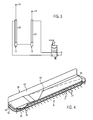
- Fig. 2 indicates at 29 the pivot bearing of each turntable 24 at the bottom of the housing 20 at.
- a deflector 28 is arranged on the upper side substantially upright or slightly inclined forward, which extends at least up to the support beam 1 facing inner end of the housing 20.
- a bearing block 32 and the inner Tragarmabrough outside a bearing block 33 is arranged on the underside. From the outer support arm 14 extends z. B. a coil spring 37 to the housing 20 of the band Rake B, wherein the spring 37 is connected at a distance from the pivot axis 18 to the housing 20. Further, between the inner end of the housing 20 and the bearing block 32, either a permanent or only as required fixable linkage 36 may be provided.
- an energy storage 35 is provided, for example in the form of a coil spring between a bearing bracket 34 on the cross member 11 and the bearing block 33 on the inner support arm 13 near the knee joint.
- the bearing block 33 could optionally be arranged on the outer support arm section 14.
- a lifting cylinder 30 is inserted above the inner Tragarmabroughes 13 between the cross member 11 and a slot guide 54 approximately the longitudinal center of the inner Tragarmabiteses 13, while on the underside of the inner Tragarmabiteses 13, a support cylinder 13 is supported, which engages the bearing block 32 of the outer Tragarmabiteses 14.
- the two cylinders 30, 32 are, preferably, single-acting hydraulic cylinders, which can be pressurized at their piston rod ends ( Fig.
- the outer arm portion 14 is shorter than the inner arm portion 13, and, for example, slightly shorter than the length of Bandrechens B. If appropriate, more than two turntables 24 may be provided on each band rake B.
- the directional control valve 38 is, for example, a two-way switching valve connecting the pump with a working line to the piston rod side chamber of the lifting cylinder 30 and at the same time the piston rod side chamber of the support cylinder 31 with the return in one switching position, while the other switching position the working line to the piston rod side chamber of the lifting cylinder 30 with the return and the piston rod-side chamber of the support cylinder 31 connects to the pump.
- Corresponding throttles or diaphragm combination can be provided either in the working lines or in the directional control valve 38, so that a predetermined sequence control can result in the actuation of the cylinders 30, 31.
- the piston-side chambers of both cylinders 30, 31 are connected to each other.
- the support cylinder 31 is relieved of pressure to the return, so that the outer arm portion 14 in the knee joint 17 in Fig. 2 pivots counterclockwise and the band rake R remains in contact with the ground, for example over a range approximately equal to the length of the belt rake B.
- the support cylinder 31 lifts, for example via the throttle assembly the band rake B from the ground and is if necessary, the pressure is blocked in order to turn the swath combination at the headland.
- the band rake B and subsequently only the windrower 7 are excavated via a positive control, and later lowered again in the same sequence.
- the inner Tragarmabites 13 can finally be swung up to an approximately vertical position (transport position) wherein both the lifting cylinder 30 and support cylinder 31 can come to a stop, and the outer Tragarmabites 14 depends approximately vertically.
- the band rake B then hangs approximately vertically on the outer support arm 14th
- the lifting cylinder 30 is first applied to release the lock with pressure, and subsequently the directional control valve 38 is switched to the other switching position, so that the retracted support cylinder 31 under the weight load starts to extend. This shifts the center of gravity and the pivot axis 18 to the outside, so that continues Pressure medium from the piston rod-side chamber of the lifting cylinder 30 is displaced and the inner Tragarmabites 13 is automatically lowered to an end position before the outer arm portion 14 is extended accordingly.
- the lifting cylinder 30 and / or the support cylinder 31 could alternatively be configured to be double-sided acted upon.
- Fig. 4 shows in a perspective view obliquely opposite to the direction of the right band rake B of Fig. 1 ,
- the housing 20 has a cover plate 42 on which the deflector 28 is arranged edgewise in the form of a sheet 43. Dashed is indicated at 44 that the sheet 43 need not be arranged parallel to the longitudinal direction of the band Rake B, but alternatively is oriented obliquely so that it backwards obliquely to the direction opposite to the direction of travel obliquely to the inside facing the support beam 1 end of the belt rake.
- the tines 21 (for example, two superimposed tines 21) are mounted with spring coils 41 on a band, not shown, of the in Fig. 4 not shown hydraulic motor is driven to a substantially elliptical orbital motion.
- a stationary deflector plate 51 may be mounted, through which the tines 21 pass.
- a Abstreifteller 39 with peripheral projections 40 rounded ridges with intervening rounded valleys
- the peripheral speed of the, preferably made of plastic, Abstreiftellers 39 may correspond to the speed of movement of the tines 21 or be higher or lower than this.
- a sub-segment of the Abstreiftellers 39 is under the cover plate 42 in the working direction A almost as far as before, as the free ends of the tines 21.
- the turntables 24 are located relatively far outside near the longitudinal ends of the belt rake B.
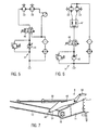
- FIGS. 5 and 6 Two exemplary hydraulic connections for the hydraulic motors 23 of the two belt rakes B are shown.
- the hydraulic motors 23 are fed from the hydraulic system H of the tractor, conveniently via a variable displacement pump 45 and a directional control valve 46 (2/2-way valve with manual or magnetic operation against a spring).
- both hydraulic motors 23 connected in series while in Fig. 6 are connected in parallel via a flow divider 47.
- the rotational speed and power of the hydraulic motors 23 determining volume flow is adjusted for example via the variable displacement pump 45 and can be varied depending on demand.
- the hydraulic system H can be provided with a load-sensing device, not shown, which increases the capacity of the variable displacement pump 45 with increasing load and reduces it as the load decreases.
- the speeds and powers of the two hydraulic motors 23 could be individually controlled and regulated or switched off, for example via an adjustable flow divider 47, which can individually change the flow rates for both hydraulic motors 23.
- Fig. 7 shows a locking mechanism R for the inner support arm portion 13.
- the locking mechanism R includes a pivotally mounted, for example, on the cross member 11 locking member 49 which is pivotable either via a hydraulic cylinder 50 or a (not shown) cable.
- a stop pin 48 is arranged, which optionally cooperates with a locking notch 51 or a locking notch 52 on the locking element 49.
- the headland position is made in which the inner Tragarmabites 13 is determined by engagement of the stop pin 48 in the locking notch 51 and under the pulling action of the lifting cylinder 30 so that the band rake B is about dug.
- the inner arm portion 13 are further pivoted up into the transport position (by the lifting cylinder 30), the pressurization of the lifting cylinder 30 is first slightly reduced until the inner Tragarmabites 13 drops under load and the stopper bolt 48 exits the locking notch 51. Then, the locking element 49 is pivoted, for example, counterclockwise. The lifting cylinder 30 is pressurized again until the inner Tragarmabites 13 has reached an approximately vertical position, while the stop pin 48 moved over the top of the locking element 49 and has fallen into the locking notch 52. Then the inner support arm 13 is blocked. In order to be able to lower the inner support arm section 13 again, in the transport position, first the lifting cylinder 30 is briefly pressurized in order to release the stop bolt 48 from the locking notch 52.
- the locking member 49 is pivoted counterclockwise, for. B. by means of the hydraulic cylinder 15, and is the in Fig. 7 not shown support cylinder 31st urged to pivot the outer support arm portion 14 to the outside, so that the weight load on the lifting cylinder 30 increases and its piston rod extends under the weight load, the locking pin 48 is guided past the locking member 49 and the inner Tragarmabites 13 lowers about the pivot axis 16, and although, preferably, to a lower end position, before the support cylinder 31 is fully extended.
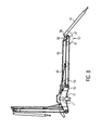
- support cylinder 31 may be omitted, wherein the positive control of the outer Tragarmabitess 14 a lying above the inner Tragarmabiteses 13, on the cross member 11 and on a control levers 57 and a pivot lever 58 hinged control rod 58 is provided.
- the control lever 57 is pivoted in the vicinity of the hinge axis 17 at a distance to its side facing the cross member 11 on the inner Tragarmabexcellent 13, while the pivot lever 58 is hinged to the outer Tragarmabrough 14 and at a distance from the hinge axis 17 at a crank 56.
- the relative pivotal movement of the outer Tragarmabiteses 14 is forcibly controlled in response to the pivotal movement of the inner Tragarmabitess 13 about the pivot axis 16, such that in the transport position with approximately vertically swung inner Tragarmabites 13 of the outer support arm 14 is pulled close to the inner Tragarmabrough 13, however in the working positions with the inner Tragarmabrough 13 includes an obtuse angle, such that the band rake B in the ground contact, for example, about 1.0 meters below the plane of the supporting beam 1, is located.
Landscapes
- Life Sciences & Earth Sciences (AREA)
- Environmental Sciences (AREA)
- Soil Working Implements (AREA)
- Folding Of Thin Sheet-Like Materials, Special Discharging Devices, And Others (AREA)
Applications Claiming Priority (1)
| Application Number | Priority Date | Filing Date | Title |
|---|---|---|---|
| DE102009034933A DE102009034933A1 (de) | 2009-07-28 | 2009-07-28 | Schwaderkombination |
Publications (3)
| Publication Number | Publication Date |
|---|---|
| EP2281435A2 true EP2281435A2 (fr) | 2011-02-09 |
| EP2281435A3 EP2281435A3 (fr) | 2011-05-18 |
| EP2281435B1 EP2281435B1 (fr) | 2013-09-04 |
Family
ID=42985471
Family Applications (1)
| Application Number | Title | Priority Date | Filing Date |
|---|---|---|---|
| EP20100007338 Active EP2281435B1 (fr) | 2009-07-28 | 2010-07-15 | Combinaison d'andain |
Country Status (2)
| Country | Link |
|---|---|
| EP (1) | EP2281435B1 (fr) |
| DE (1) | DE102009034933A1 (fr) |
Cited By (8)
| Publication number | Priority date | Publication date | Assignee | Title |
|---|---|---|---|---|
| EP2520156A1 (fr) * | 2011-05-03 | 2012-11-07 | CLAAS Saulgau GmbH | Moissonneuse avec au moins deux convoyeurs transversaux |
| EP3025577A1 (fr) | 2014-11-25 | 2016-06-01 | Kverneland Group Kerteminde AS | Andaineur universel |
| FR3032857A1 (fr) * | 2015-02-20 | 2016-08-26 | Bionalan | Andaineur de menue paille |
| EP3092888A1 (fr) * | 2015-05-12 | 2016-11-16 | Forage Innovations B.V. | Machine agricole |
| CN114196491A (zh) * | 2021-10-29 | 2022-03-18 | 安徽王仁和米线食品有限公司 | 一种酒糟摊凉冷却装置 |
| US20230371433A1 (en) * | 2022-05-17 | 2023-11-23 | Vermeer Manufacturing Company | Rake apparatus |
| US12648521B2 (en) * | 2021-07-23 | 2026-06-09 | Claas Saulgau Gmbh | Rotary rake |
| US12677745B2 (en) | 2022-08-29 | 2026-07-14 | Deere & Company | Rake implement with moveable tongue |
Families Citing this family (2)
| Publication number | Priority date | Publication date | Assignee | Title |
|---|---|---|---|---|
| DE102016117117A1 (de) | 2016-09-12 | 2018-03-15 | Claas Saulgau Gmbh | Schwader und Verfahren zum Betreiben desselben |
| US10299437B2 (en) * | 2017-07-17 | 2019-05-28 | Cnh Industrial America Llc | Header for an agricultural vehicle with deformable supports |
Citations (10)
| Publication number | Priority date | Publication date | Assignee | Title |
|---|---|---|---|---|
| DE1034905B (de) | 1953-05-11 | 1958-07-24 | Heinrich Lanz Ag | Geraet zum Bearbeiten von halm-, blatt- oder stengelartigem Erntegut, wie z. B. Gras, Heu, Stroh usw. |
| DE2356623A1 (de) | 1972-11-13 | 1974-05-16 | Otto Gruber | Schwadenbildegeraet |
| GB1472122A (en) | 1973-04-13 | 1977-05-04 | Lely Nv C Van Der | Crop mowing and/or haymaking machines |
| DE19603400A1 (de) | 1996-01-31 | 1997-08-07 | Claas Saulgau Gmbh | Landwirtschaftliche Maschine mit in Fahrtrichtung gestaffelt angeordneten Arbeitswerkzeugen |
| EP0978228A1 (fr) | 1998-08-03 | 2000-02-09 | Maasland N.V. | Dispositif pour déplacer des végétaux se trouvant sur le sol |
| DE10327884B4 (de) | 2003-06-20 | 2006-01-05 | Maschinenfabrik Bernard Krone Gmbh | Heuwerbungsmaschine |
| DE102005018987A1 (de) | 2005-04-22 | 2006-11-09 | Gerhard Dücker GmbH & Co. KG Landmaschinenfabrik | Mäh- und/oder Schneidgerät |
| EP1084605B1 (fr) | 1999-09-16 | 2008-05-07 | Franz Schuler | Rateau andainer pour remorque chargeuse |
| DE102007051188A1 (de) | 2006-12-20 | 2008-06-26 | Alois Pöttinger Maschinenfabrik Gmbh | Heuwerbungsmaschine |
| DE102007035407A1 (de) | 2007-07-26 | 2009-04-16 | Claas Saulgau Gmbh | Heuwerbungsmaschine |
Family Cites Families (7)
| Publication number | Priority date | Publication date | Assignee | Title |
|---|---|---|---|---|
| DE9112331U1 (de) * | 1991-10-04 | 1991-12-12 | Maschinenfabriken Bernard Krone Gmbh, 4441 Spelle | Mähmaschine |
| DE19535453A1 (de) * | 1994-11-18 | 1997-03-27 | Claas Saulgau Gmbh | Schneid- und Förderwerk für stengelige Erntegüter |
| DE29708799U1 (de) * | 1997-05-17 | 1997-08-07 | Wilhelm Stoll Maschinenfabrik Gmbh, 38268 Lengede | Mehrkreiseliger Großschwader |
| DE29818457U1 (de) * | 1998-10-15 | 1998-12-17 | Multinorm B.V., Nieuw-Vennep | Landwirtschaftliche Bearbeitungsmaschine |
| DE20109124U1 (de) * | 2001-05-31 | 2001-09-20 | Kverneland Asa, Kverneland | Schwadgerät |
| DE10327917B4 (de) * | 2003-06-20 | 2005-12-08 | Maschinenfabrik Bernard Krone Gmbh | Heuwerbungsmaschine |
| CH701573B1 (de) * | 2007-10-12 | 2011-02-15 | Thomas Erni | Vorrichtung zum Bergen von Gras oder Futter. |
-
2009
- 2009-07-28 DE DE102009034933A patent/DE102009034933A1/de not_active Withdrawn
-
2010
- 2010-07-15 EP EP20100007338 patent/EP2281435B1/fr active Active
Patent Citations (10)
| Publication number | Priority date | Publication date | Assignee | Title |
|---|---|---|---|---|
| DE1034905B (de) | 1953-05-11 | 1958-07-24 | Heinrich Lanz Ag | Geraet zum Bearbeiten von halm-, blatt- oder stengelartigem Erntegut, wie z. B. Gras, Heu, Stroh usw. |
| DE2356623A1 (de) | 1972-11-13 | 1974-05-16 | Otto Gruber | Schwadenbildegeraet |
| GB1472122A (en) | 1973-04-13 | 1977-05-04 | Lely Nv C Van Der | Crop mowing and/or haymaking machines |
| DE19603400A1 (de) | 1996-01-31 | 1997-08-07 | Claas Saulgau Gmbh | Landwirtschaftliche Maschine mit in Fahrtrichtung gestaffelt angeordneten Arbeitswerkzeugen |
| EP0978228A1 (fr) | 1998-08-03 | 2000-02-09 | Maasland N.V. | Dispositif pour déplacer des végétaux se trouvant sur le sol |
| EP1084605B1 (fr) | 1999-09-16 | 2008-05-07 | Franz Schuler | Rateau andainer pour remorque chargeuse |
| DE10327884B4 (de) | 2003-06-20 | 2006-01-05 | Maschinenfabrik Bernard Krone Gmbh | Heuwerbungsmaschine |
| DE102005018987A1 (de) | 2005-04-22 | 2006-11-09 | Gerhard Dücker GmbH & Co. KG Landmaschinenfabrik | Mäh- und/oder Schneidgerät |
| DE102007051188A1 (de) | 2006-12-20 | 2008-06-26 | Alois Pöttinger Maschinenfabrik Gmbh | Heuwerbungsmaschine |
| DE102007035407A1 (de) | 2007-07-26 | 2009-04-16 | Claas Saulgau Gmbh | Heuwerbungsmaschine |
Cited By (11)
| Publication number | Priority date | Publication date | Assignee | Title |
|---|---|---|---|---|
| EP2520156A1 (fr) * | 2011-05-03 | 2012-11-07 | CLAAS Saulgau GmbH | Moissonneuse avec au moins deux convoyeurs transversaux |
| EP3025577A1 (fr) | 2014-11-25 | 2016-06-01 | Kverneland Group Kerteminde AS | Andaineur universel |
| FR3032857A1 (fr) * | 2015-02-20 | 2016-08-26 | Bionalan | Andaineur de menue paille |
| EP3092888A1 (fr) * | 2015-05-12 | 2016-11-16 | Forage Innovations B.V. | Machine agricole |
| NL2014796A (en) * | 2015-05-12 | 2016-11-21 | Forage Innovations Bv | Agricultural machine. |
| US12648521B2 (en) * | 2021-07-23 | 2026-06-09 | Claas Saulgau Gmbh | Rotary rake |
| CN114196491A (zh) * | 2021-10-29 | 2022-03-18 | 安徽王仁和米线食品有限公司 | 一种酒糟摊凉冷却装置 |
| CN114196491B (zh) * | 2021-10-29 | 2023-08-22 | 安徽王仁和米线食品有限公司 | 一种酒糟摊凉冷却装置 |
| US20230371433A1 (en) * | 2022-05-17 | 2023-11-23 | Vermeer Manufacturing Company | Rake apparatus |
| US12610890B2 (en) * | 2022-05-17 | 2026-04-28 | Vermeer Manufacturing Company | Rake apparatus |
| US12677745B2 (en) | 2022-08-29 | 2026-07-14 | Deere & Company | Rake implement with moveable tongue |
Also Published As
| Publication number | Publication date |
|---|---|
| DE102009034933A1 (de) | 2011-02-03 |
| EP2281435A3 (fr) | 2011-05-18 |
| EP2281435B1 (fr) | 2013-09-04 |
Similar Documents
| Publication | Publication Date | Title |
|---|---|---|
| EP2281435B1 (fr) | Combinaison d'andain | |
| DE2814399C2 (fr) | ||
| DE602004009338T2 (de) | Landmaschine zum schwaden von auf dem boden liegenden produkten | |
| EP2022316B1 (fr) | Machine de fenaison | |
| EP0339231A2 (fr) | Machine agricole de fauchage et de fenaison | |
| EP2529614B1 (fr) | Combinaison de mécanisme de tonte | |
| DE102004032065A1 (de) | Stützradmechanismus an einem Vorsatzgerät | |
| DE19952555A1 (de) | Heuwerbungsmaschine | |
| DE4340384B4 (de) | Heuwerbungsmaschine | |
| EP0559024A1 (fr) | Machine de fenaison | |
| WO2009071255A1 (fr) | Machine automotrice pour la cueillette dans des plantations | |
| DE202009003439U1 (de) | Heuwerbungsmaschine | |
| DE29818457U1 (de) | Landwirtschaftliche Bearbeitungsmaschine | |
| DE202018106434U1 (de) | Landwirtschaftliches Anbaugerät | |
| EP0937382B1 (fr) | Faneuse rotative | |
| DE102006034562A1 (de) | Anbaumäher | |
| DE1430138C3 (de) | Steuereinrichtung für ein hydrostatisches Getriebe eines mit einer Anhängevorrichtung bzw. einem Geräteanschluß ausgerüsteten Schleppers | |
| DE202017107372U1 (de) | Landwirtschaftliche Ernte- und/oder Bodenbearbeitungsmaschine | |
| EP3025577B1 (fr) | Andaineur universel | |
| EP1588601A1 (fr) | Machine de récolte avec un dispositif de décharge | |
| DE602005005143T2 (de) | Heuwerbungsmaschine | |
| EP1618778B1 (fr) | Andaineuse rotative | |
| EP3791706B1 (fr) | Machine de travail agricole pourvue d'outil de travail réglable en hauteur | |
| EP1974599B1 (fr) | Faneuse | |
| DE2416317A1 (de) | Heuwerbungsmaschine |
Legal Events
| Date | Code | Title | Description |
|---|---|---|---|
| PUAI | Public reference made under article 153(3) epc to a published international application that has entered the european phase |
Free format text: ORIGINAL CODE: 0009012 |
|
| AK | Designated contracting states |
Kind code of ref document: A2 Designated state(s): AL AT BE BG CH CY CZ DE DK EE ES FI FR GB GR HR HU IE IS IT LI LT LU LV MC MK MT NL NO PL PT RO SE SI SK SM TR |
|
| AX | Request for extension of the european patent |
Extension state: BA ME RS |
|
| PUAL | Search report despatched |
Free format text: ORIGINAL CODE: 0009013 |
|
| AK | Designated contracting states |
Kind code of ref document: A3 Designated state(s): AL AT BE BG CH CY CZ DE DK EE ES FI FR GB GR HR HU IE IS IT LI LT LU LV MC MK MT NL NO PL PT RO SE SI SK SM TR |
|
| AX | Request for extension of the european patent |
Extension state: BA ME RS |
|
| 17P | Request for examination filed |
Effective date: 20110706 |
|
| GRAP | Despatch of communication of intention to grant a patent |
Free format text: ORIGINAL CODE: EPIDOSNIGR1 |
|
| GRAS | Grant fee paid |
Free format text: ORIGINAL CODE: EPIDOSNIGR3 |
|
| RAP1 | Party data changed (applicant data changed or rights of an application transferred) |
Owner name: KVERNELAND AS |
|
| GRAA | (expected) grant |
Free format text: ORIGINAL CODE: 0009210 |
|
| AK | Designated contracting states |
Kind code of ref document: B1 Designated state(s): AL AT BE BG CH CY CZ DE DK EE ES FI FR GB GR HR HU IE IS IT LI LT LU LV MC MK MT NL NO PL PT RO SE SI SK SM TR |
|
| REG | Reference to a national code |
Ref country code: GB Ref legal event code: FG4D Free format text: NOT ENGLISH |
|
| REG | Reference to a national code |
Ref country code: CH Ref legal event code: EP |
|
| REG | Reference to a national code |
Ref country code: AT Ref legal event code: REF Ref document number: 629952 Country of ref document: AT Kind code of ref document: T Effective date: 20130915 |
|
| REG | Reference to a national code |
Ref country code: IE Ref legal event code: FG4D Free format text: LANGUAGE OF EP DOCUMENT: GERMAN |
|
| REG | Reference to a national code |
Ref country code: DE Ref legal event code: R096 Ref document number: 502010004578 Country of ref document: DE Effective date: 20131031 |
|
| REG | Reference to a national code |
Ref country code: NL Ref legal event code: VDEP Effective date: 20130904 |
|
| PG25 | Lapsed in a contracting state [announced via postgrant information from national office to epo] |
Ref country code: NO Free format text: LAPSE BECAUSE OF FAILURE TO SUBMIT A TRANSLATION OF THE DESCRIPTION OR TO PAY THE FEE WITHIN THE PRESCRIBED TIME-LIMIT Effective date: 20131204 Ref country code: SE Free format text: LAPSE BECAUSE OF FAILURE TO SUBMIT A TRANSLATION OF THE DESCRIPTION OR TO PAY THE FEE WITHIN THE PRESCRIBED TIME-LIMIT Effective date: 20130904 Ref country code: CY Free format text: LAPSE BECAUSE OF FAILURE TO SUBMIT A TRANSLATION OF THE DESCRIPTION OR TO PAY THE FEE WITHIN THE PRESCRIBED TIME-LIMIT Effective date: 20130918 Ref country code: HR Free format text: LAPSE BECAUSE OF FAILURE TO SUBMIT A TRANSLATION OF THE DESCRIPTION OR TO PAY THE FEE WITHIN THE PRESCRIBED TIME-LIMIT Effective date: 20130904 Ref country code: LT Free format text: LAPSE BECAUSE OF FAILURE TO SUBMIT A TRANSLATION OF THE DESCRIPTION OR TO PAY THE FEE WITHIN THE PRESCRIBED TIME-LIMIT Effective date: 20130904 |
|
| REG | Reference to a national code |
Ref country code: NL Ref legal event code: VDEP Effective date: 20130904 |
|
| REG | Reference to a national code |
Ref country code: LT Ref legal event code: MG4D |
|
| PG25 | Lapsed in a contracting state [announced via postgrant information from national office to epo] |
Ref country code: PL Free format text: LAPSE BECAUSE OF FAILURE TO SUBMIT A TRANSLATION OF THE DESCRIPTION OR TO PAY THE FEE WITHIN THE PRESCRIBED TIME-LIMIT Effective date: 20130904 Ref country code: SI Free format text: LAPSE BECAUSE OF FAILURE TO SUBMIT A TRANSLATION OF THE DESCRIPTION OR TO PAY THE FEE WITHIN THE PRESCRIBED TIME-LIMIT Effective date: 20130904 Ref country code: GR Free format text: LAPSE BECAUSE OF FAILURE TO SUBMIT A TRANSLATION OF THE DESCRIPTION OR TO PAY THE FEE WITHIN THE PRESCRIBED TIME-LIMIT Effective date: 20131205 Ref country code: FI Free format text: LAPSE BECAUSE OF FAILURE TO SUBMIT A TRANSLATION OF THE DESCRIPTION OR TO PAY THE FEE WITHIN THE PRESCRIBED TIME-LIMIT Effective date: 20130904 Ref country code: LV Free format text: LAPSE BECAUSE OF FAILURE TO SUBMIT A TRANSLATION OF THE DESCRIPTION OR TO PAY THE FEE WITHIN THE PRESCRIBED TIME-LIMIT Effective date: 20130904 |
|
| PG25 | Lapsed in a contracting state [announced via postgrant information from national office to epo] |
Ref country code: CY Free format text: LAPSE BECAUSE OF FAILURE TO SUBMIT A TRANSLATION OF THE DESCRIPTION OR TO PAY THE FEE WITHIN THE PRESCRIBED TIME-LIMIT Effective date: 20130904 |
|
| PG25 | Lapsed in a contracting state [announced via postgrant information from national office to epo] |
Ref country code: CZ Free format text: LAPSE BECAUSE OF FAILURE TO SUBMIT A TRANSLATION OF THE DESCRIPTION OR TO PAY THE FEE WITHIN THE PRESCRIBED TIME-LIMIT Effective date: 20130904 Ref country code: EE Free format text: LAPSE BECAUSE OF FAILURE TO SUBMIT A TRANSLATION OF THE DESCRIPTION OR TO PAY THE FEE WITHIN THE PRESCRIBED TIME-LIMIT Effective date: 20130904 Ref country code: NL Free format text: LAPSE BECAUSE OF FAILURE TO SUBMIT A TRANSLATION OF THE DESCRIPTION OR TO PAY THE FEE WITHIN THE PRESCRIBED TIME-LIMIT Effective date: 20130904 Ref country code: RO Free format text: LAPSE BECAUSE OF FAILURE TO SUBMIT A TRANSLATION OF THE DESCRIPTION OR TO PAY THE FEE WITHIN THE PRESCRIBED TIME-LIMIT Effective date: 20130904 Ref country code: SK Free format text: LAPSE BECAUSE OF FAILURE TO SUBMIT A TRANSLATION OF THE DESCRIPTION OR TO PAY THE FEE WITHIN THE PRESCRIBED TIME-LIMIT Effective date: 20130904 Ref country code: IS Free format text: LAPSE BECAUSE OF FAILURE TO SUBMIT A TRANSLATION OF THE DESCRIPTION OR TO PAY THE FEE WITHIN THE PRESCRIBED TIME-LIMIT Effective date: 20140104 |
|
| PG25 | Lapsed in a contracting state [announced via postgrant information from national office to epo] |
Ref country code: ES Free format text: LAPSE BECAUSE OF FAILURE TO SUBMIT A TRANSLATION OF THE DESCRIPTION OR TO PAY THE FEE WITHIN THE PRESCRIBED TIME-LIMIT Effective date: 20130904 |
|
| REG | Reference to a national code |
Ref country code: DE Ref legal event code: R097 Ref document number: 502010004578 Country of ref document: DE |
|
| PG25 | Lapsed in a contracting state [announced via postgrant information from national office to epo] |
Ref country code: PT Free format text: LAPSE BECAUSE OF FAILURE TO SUBMIT A TRANSLATION OF THE DESCRIPTION OR TO PAY THE FEE WITHIN THE PRESCRIBED TIME-LIMIT Effective date: 20140106 |
|
| PLBE | No opposition filed within time limit |
Free format text: ORIGINAL CODE: 0009261 |
|
| STAA | Information on the status of an ep patent application or granted ep patent |
Free format text: STATUS: NO OPPOSITION FILED WITHIN TIME LIMIT |
|
| 26N | No opposition filed |
Effective date: 20140605 |
|
| PG25 | Lapsed in a contracting state [announced via postgrant information from national office to epo] |
Ref country code: IT Free format text: LAPSE BECAUSE OF FAILURE TO SUBMIT A TRANSLATION OF THE DESCRIPTION OR TO PAY THE FEE WITHIN THE PRESCRIBED TIME-LIMIT Effective date: 20130904 |
|
| REG | Reference to a national code |
Ref country code: DE Ref legal event code: R097 Ref document number: 502010004578 Country of ref document: DE Effective date: 20140605 |
|
| PG25 | Lapsed in a contracting state [announced via postgrant information from national office to epo] |
Ref country code: DK Free format text: LAPSE BECAUSE OF FAILURE TO SUBMIT A TRANSLATION OF THE DESCRIPTION OR TO PAY THE FEE WITHIN THE PRESCRIBED TIME-LIMIT Effective date: 20130904 |
|
| PG25 | Lapsed in a contracting state [announced via postgrant information from national office to epo] |
Ref country code: LU Free format text: LAPSE BECAUSE OF FAILURE TO SUBMIT A TRANSLATION OF THE DESCRIPTION OR TO PAY THE FEE WITHIN THE PRESCRIBED TIME-LIMIT Effective date: 20140715 |
|
| REG | Reference to a national code |
Ref country code: CH Ref legal event code: PL |
|
| REG | Reference to a national code |
Ref country code: IE Ref legal event code: MM4A |
|
| PG25 | Lapsed in a contracting state [announced via postgrant information from national office to epo] |
Ref country code: CH Free format text: LAPSE BECAUSE OF NON-PAYMENT OF DUE FEES Effective date: 20140731 Ref country code: LI Free format text: LAPSE BECAUSE OF NON-PAYMENT OF DUE FEES Effective date: 20140731 |
|
| PG25 | Lapsed in a contracting state [announced via postgrant information from national office to epo] |
Ref country code: IE Free format text: LAPSE BECAUSE OF NON-PAYMENT OF DUE FEES Effective date: 20140715 |
|
| PG25 | Lapsed in a contracting state [announced via postgrant information from national office to epo] |
Ref country code: SM Free format text: LAPSE BECAUSE OF FAILURE TO SUBMIT A TRANSLATION OF THE DESCRIPTION OR TO PAY THE FEE WITHIN THE PRESCRIBED TIME-LIMIT Effective date: 20130904 Ref country code: MC Free format text: LAPSE BECAUSE OF FAILURE TO SUBMIT A TRANSLATION OF THE DESCRIPTION OR TO PAY THE FEE WITHIN THE PRESCRIBED TIME-LIMIT Effective date: 20130904 |
|
| PG25 | Lapsed in a contracting state [announced via postgrant information from national office to epo] |
Ref country code: MT Free format text: LAPSE BECAUSE OF FAILURE TO SUBMIT A TRANSLATION OF THE DESCRIPTION OR TO PAY THE FEE WITHIN THE PRESCRIBED TIME-LIMIT Effective date: 20130904 Ref country code: BG Free format text: LAPSE BECAUSE OF FAILURE TO SUBMIT A TRANSLATION OF THE DESCRIPTION OR TO PAY THE FEE WITHIN THE PRESCRIBED TIME-LIMIT Effective date: 20130904 |
|
| REG | Reference to a national code |
Ref country code: FR Ref legal event code: PLFP Year of fee payment: 7 |
|
| PG25 | Lapsed in a contracting state [announced via postgrant information from national office to epo] |
Ref country code: TR Free format text: LAPSE BECAUSE OF FAILURE TO SUBMIT A TRANSLATION OF THE DESCRIPTION OR TO PAY THE FEE WITHIN THE PRESCRIBED TIME-LIMIT Effective date: 20130904 Ref country code: BE Free format text: LAPSE BECAUSE OF FAILURE TO SUBMIT A TRANSLATION OF THE DESCRIPTION OR TO PAY THE FEE WITHIN THE PRESCRIBED TIME-LIMIT Effective date: 20140731 Ref country code: HU Free format text: LAPSE BECAUSE OF FAILURE TO SUBMIT A TRANSLATION OF THE DESCRIPTION OR TO PAY THE FEE WITHIN THE PRESCRIBED TIME-LIMIT; INVALID AB INITIO Effective date: 20100715 |
|
| REG | Reference to a national code |
Ref country code: FR Ref legal event code: PLFP Year of fee payment: 8 |
|
| PG25 | Lapsed in a contracting state [announced via postgrant information from national office to epo] |
Ref country code: MK Free format text: LAPSE BECAUSE OF FAILURE TO SUBMIT A TRANSLATION OF THE DESCRIPTION OR TO PAY THE FEE WITHIN THE PRESCRIBED TIME-LIMIT Effective date: 20130904 |
|
| REG | Reference to a national code |
Ref country code: FR Ref legal event code: PLFP Year of fee payment: 9 |
|
| PG25 | Lapsed in a contracting state [announced via postgrant information from national office to epo] |
Ref country code: AL Free format text: LAPSE BECAUSE OF FAILURE TO SUBMIT A TRANSLATION OF THE DESCRIPTION OR TO PAY THE FEE WITHIN THE PRESCRIBED TIME-LIMIT Effective date: 20130904 |
|
| REG | Reference to a national code |
Ref country code: DE Ref legal event code: R082 Ref document number: 502010004578 Country of ref document: DE Representative=s name: KILBURN & STRODE LLP, NL |
|
| P01 | Opt-out of the competence of the unified patent court (upc) registered |
Effective date: 20230525 |
|
| PGFP | Annual fee paid to national office [announced via postgrant information from national office to epo] |
Ref country code: DE Payment date: 20250722 Year of fee payment: 16 |
|
| PGFP | Annual fee paid to national office [announced via postgrant information from national office to epo] |
Ref country code: GB Payment date: 20250722 Year of fee payment: 16 |
|
| PGFP | Annual fee paid to national office [announced via postgrant information from national office to epo] |
Ref country code: FR Payment date: 20250725 Year of fee payment: 16 Ref country code: AT Payment date: 20250722 Year of fee payment: 16 |