EP2281479A1 - Faltbares Regal - Google Patents
Faltbares Regal Download PDFInfo
- Publication number
- EP2281479A1 EP2281479A1 EP09164259A EP09164259A EP2281479A1 EP 2281479 A1 EP2281479 A1 EP 2281479A1 EP 09164259 A EP09164259 A EP 09164259A EP 09164259 A EP09164259 A EP 09164259A EP 2281479 A1 EP2281479 A1 EP 2281479A1
- Authority
- EP
- European Patent Office
- Prior art keywords
- shelf
- foldable
- rear wall
- front wall
- fixing means
- Prior art date
- Legal status (The legal status is an assumption and is not a legal conclusion. Google has not performed a legal analysis and makes no representation as to the accuracy of the status listed.)
- Granted
Links
- 239000000463 material Substances 0.000 claims abstract description 35
- 238000000034 method Methods 0.000 claims abstract description 7
- 238000003825 pressing Methods 0.000 claims description 2
- 239000010410 layer Substances 0.000 description 13
- 238000005452 bending Methods 0.000 description 6
- 239000000853 adhesive Substances 0.000 description 5
- 230000001070 adhesive effect Effects 0.000 description 5
- 238000004806 packaging method and process Methods 0.000 description 5
- 239000003292 glue Substances 0.000 description 4
- 238000004519 manufacturing process Methods 0.000 description 4
- OKTJSMMVPCPJKN-UHFFFAOYSA-N Carbon Chemical compound [C] OKTJSMMVPCPJKN-UHFFFAOYSA-N 0.000 description 3
- 238000010276 construction Methods 0.000 description 3
- 239000006228 supernatant Substances 0.000 description 2
- 230000006978 adaptation Effects 0.000 description 1
- 239000000969 carrier Substances 0.000 description 1
- 239000004744 fabric Substances 0.000 description 1
- 230000002349 favourable effect Effects 0.000 description 1
- 238000003780 insertion Methods 0.000 description 1
- 230000037431 insertion Effects 0.000 description 1
- 238000009434 installation Methods 0.000 description 1
- 239000002655 kraft paper Substances 0.000 description 1
- 239000003562 lightweight material Substances 0.000 description 1
- 239000010893 paper waste Substances 0.000 description 1
- 239000000047 product Substances 0.000 description 1
- 238000004080 punching Methods 0.000 description 1
- 230000002787 reinforcement Effects 0.000 description 1
- 239000002356 single layer Substances 0.000 description 1
- 239000002689 soil Substances 0.000 description 1
- 230000006641 stabilisation Effects 0.000 description 1
- 238000011105 stabilization Methods 0.000 description 1
- 238000003860 storage Methods 0.000 description 1
- 239000002699 waste material Substances 0.000 description 1
Images



Classifications
-
- A—HUMAN NECESSITIES
- A47—FURNITURE; DOMESTIC ARTICLES OR APPLIANCES; COFFEE MILLS; SPICE MILLS; SUCTION CLEANERS IN GENERAL
- A47F—SPECIAL FURNITURE, FITTINGS, OR ACCESSORIES FOR SHOPS, STOREHOUSES, BARS, RESTAURANTS OR THE LIKE; PAYING COUNTERS
- A47F5/00—Show stands, hangers, or shelves characterised by their constructional features
- A47F5/10—Adjustable or foldable or dismountable display stands
- A47F5/11—Adjustable or foldable or dismountable display stands made of cardboard, paper or the like
- A47F5/112—Adjustable or foldable or dismountable display stands made of cardboard, paper or the like hand-folded from sheet material
- A47F5/116—Shelving racks
-
- A—HUMAN NECESSITIES
- A47—FURNITURE; DOMESTIC ARTICLES OR APPLIANCES; COFFEE MILLS; SPICE MILLS; SUCTION CLEANERS IN GENERAL
- A47B—TABLES; DESKS; OFFICE FURNITURE; CABINETS; DRAWERS; GENERAL DETAILS OF FURNITURE
- A47B43/00—Cabinets, racks or shelf units, characterised by features enabling folding of the cabinet or the like
- A47B43/02—Cabinets, racks or shelf units, characterised by features enabling folding of the cabinet or the like made of cardboard or the like
Definitions
- the present invention relates to a foldable shelf, which can be produced from at least one shelf element.
- This shelf is also suitable for use as a display stand in a sales room.
- Such displays are found in the retail sector, such as in supermarkets, drugstores and generally in sales areas.
- the U.S. Patent 4,311,100 discloses a fabric stand that can be made substantially from a one-piece blank.
- the material for the floors is folded out of the otherwise intended for the front part of the blank.
- this stand may be useful for many purposes, a construction without a front wall and without support of shelves, such as by transverse webs in the front wall, requires the use of a relatively strong and therefore expensive material.
- the floors allow no special adaptation to be placed there goods. Goods are therefore not kept in a special way, so that they can be offered in an ideal predetermined sales position or that they are protected against falling out forward.
- the shelf element shown has partially open side walls. These side walls, which have triangular open sections, are intended to provide lateral access to the shelves. These accesses are not very useful if such stands are to be connected together to form a larger rack unit.
- the patent application WO 2007/148963 discloses a foldable goods shelf.
- This shelf is composed of a relatively large number of individual parts and is provided in a preferred embodiment with a mechanical deployment aid.
- the right and the left side wall is folded inwards, so in each case to the rear wall.
- both side walls move in opposite direction to the outside, that is, the left side wall folds away from the rear wall to the left and the right side wall folds away from the rear wall to the right.
- This erection mechanism means that you can not easily connect several such shelf parts together. In particular, it would be impossible to glue side walls of adjacent shelf parts together, as this would block the erection mechanism.
- the publication DE 101 45 859 A1 discloses a folding shelving system. This should be offered for example as a CD shelf or shelf for file folders.
- the honeycomb shape of the shelf elements may well harmonize with the folding mechanism, but means a certain waste of space when storing cuboid objects. Also, objects are not secured against falling out forward. Rough shelves and sturdy hinges seem to be required to accommodate the folding mechanism.
- the utility model DE G 87 13 942.1 discloses furniture made of corrugated cardboard or similar foldable material.
- the furniture is intended to be a useful product of waste paper. In particular, it can serve as a classroom furniture with compartments and drawers. However, it is obvious that even the production of the large number of drawn-out drawers and drawers complicates the manufacture and construction of the furniture.
- a stable shelf should be provided cheaply. It should be the transport of the required material bequen and the shelf should be easy to build by an untrained individual or untrained person. Furthermore, the shelf should also be made of lightweight material. This is achieved by the shelf according to claim 1.
- the present invention relates to a foldable shelf, which can be produced from at least one shelf element.
- a foldable shelf which comprises at least a first shelf element with a rear wall, two side walls and a partially perforated front wall, which further comprises at least one shelf, wherein the at least one shelf is movably connected to the rear wall and on the front wall a first Fixing means (for example, plug-in means) for fixing the at least one shelf is provided and further comprising at least one shelf a second fixing means (for example, receptacles) for connection to the first fixing means and the shelf of a folding arrangement, in which the at least one shelf rests against the rear wall and the shelf walls include substantially no usable space, can be converted into a utility arrangement, in which the at least one shelf with the first fixing means, is connected to the front wall and the shelf walls include a work space.
- the invention thus relates to a foldable shelf, which comprises at least a first shelf element.
- the foldable shelf may well include several shelf elements. For example, a linear arrangement of three or four shelf elements could be offered as a shelf. This in particular if the various elements have a common base or a common head attachment.
- the first shelf element but usually all other shelf elements should include a rear wall, two side walls and a front wall. These walls can in principle include any shape, usually they will include a cuboid.
- the front wall is broken. So there are suitable openings to provide, which allow access to the shelf interior.
- the first shelf element should comprise at least one shelf.
- This shelf is movably connected to the rear wall.
- the shelf is connected to another wall, for example one of the side walls.
- the mobility of the at least one shelf to the rear wall should be such that the shelf can be connected in at least one position with the front wall and fixed there.
- the front wall for this purpose has first and second fixing means, which are provided at least preferably in the form of a plug-in means as a first fixing means and in the form of a receptacle as a corresponding second fixing means.
- the recording is provided on or in the shelf.
- the feature described herein of the at least one shelf should also have all other shelves, if a plurality of shelves is provided. Also apply herein for a shelf element made statement also for other shelf elements of a foldable shelf.
- the shelf and the shelf elements should be convertible into a folding arrangement.
- the at least one shelf should in any case abut substantially on the rear wall or, if a small distance should still remain between the rear wall and the shelf, come to lie substantially parallel to the rear wall. If several shelves are provided, they should all be brought into this position in the folding arrangement.
- the shelves and the shelf elements do not include a usable space or at least substantially no usable space. If, for example, walls are not folded completely flush with one another, then a small space may remain, which however is not available as usable space in the sense of a useful space of a shelf.
- the shelf and the shelf elements should be able to be converted into a utility arrangement.
- the shelf is connected to the front wall with the aid of the fixing means, preferably with the aid of the insertion means, which has the front wall.
- the utility arrangement is one in which the shelf walls complete a utility space.
- the at least one shelf is movable relative to the rear wall in such a way that it can be tilted about an axis.
- the mobility of the shelf and in particular the mobility of the shelf is made about an axis by the flexibility of the material from which the at least one shelf is made.
- the at least one shelf may well consist of several different materials. However, it has proved possible and advantageous to produce the shelf as a blank of a material web. It is also possible to choose this material web so that the required flexibility is provided.
- the material web can be made, for example, of plastic or of cardboard, in particular of kraft cardboard or corrugated cardboard.
- the material web jacket blank can be single-layered or a laminate.
- a shelf from two layers of material.
- These can be, for example, two layers of material from the same blank from the material web when it is folded.
- the two layers of material can be arranged so that one part of the shelf consists only of one material layer and another part of the shelf consists of two layers of material.
- the axis by which the shelf can be tilted relative to the rear wall lie in the part of the floor, which made from a material layer.
- the usually higher flexibility of a material layer in comparison to a double material layer is used in this way. At the same time, however, it is possible to ensure adequate reinforcement of the shelf at other locations.
- the invention can be carried out so that the receptacle of the at least one shelf, which serves for connection to the plug-in means, is designed as a slot.
- a slot may be a groove-like depression in the shelf or may alternatively and even preferably pass through the entire depth of the shelf so that a slot-shaped opening is formed.
- the front wall offers transverse webs, which are a support for the at least one shelf, typically in a front portion of the shelf. These transverse webs may be, for example, the lower limits of the openings in the front wall.
- the transverse webs have upwardly directed lugs.
- These lugs are a form of the first fixing means and can be taken up by the second fixing means, ie in particular by the slots. With open slots, it is also possible that the lugs protrude through the slot and thus form a supernatant at the top of the shelves. Such a supernatant can be used deliberately to avoid falling out of objects from the shelves to the front.
- the at least one shelf may also be useful to arrange the at least one shelf obliquely, in the form that it falls off at least in a portion of the front wall to the rear wall.
- the shelf level it is also possible to provide the shelf level. It is also useful if the at least one shelf has a rear impact. A good placed on the shelf can then be placed so that it rests against the kick.
- the shelf can be matched to objects of certain shape, in particular certain rectangular cross-section. It can be optimized for both different objects, as well as objects of identical rectangular cross-section.
- an object of rectangular cross-section when it rests with its rear lower edge on the rear abutment, just with its rear upper edge abuts against the rear wall. This results in the article being supported at two points in the back. Consequently, the object is stable on the shelf and finds a clearly predefined position on the shelf.
- the shelf is therefore particularly suitable for the presentation and storage of books, such as paperbacks, and sound and image carriers, such as CD's, video cassettes and DVD's. Therefore, in addition to the use in private rooms, it can also be used well in the sales room of a bookstore or video store.
- a foldable shelf according to the invention may for example comprise two, three, four, five or six shelf elements.
- a foldable shelf comprising four shelf elements is particularly convenient. It may be particularly expedient to arrange the four shelf elements to a rectangle or square. Preferably, this is done so that the front walls of the corresponding shelf elements in the supervision describe a rectangle or square.
- a foldable shelf which can take a flat folding position. It is very useful if the foldable shelf in one square-shaped outer packaging can be placed, the amount of which is significantly less than the length of their shortest side. Preferably, this height is only one-tenth or less than the length of the shortest side.
- the invention also relates to a method for setting up a foldable shelf.
- This method comprises at least the following steps: (a) applying pressure to two opposite edges of the foldable shelf; (b) folding down the at least one shelf; (C) fixing the at least one shelf with the help of the plug means and the receptacle for connection to the plug means.
- the method may further include, prior to step (a), removing one of the foldable shelves from a cuboid overwrap.
- Fig. 1 shows first a blank 12, from which substantially the walls of a shelf element according to the invention can be produced. From the left section of the blank, the rear wall 30 is formed, from the subsequent narrower section, the second side wall 34 is formed the subsequent section creates the front wall 36 and from the adjoining section, the first side wall 32 is formed. Particularly cost-saving is the use of rectangular blanks and thus also the production of rectangular side walls and corresponding cuboid shelf elements.
- the blank has lateral tabs, which are not specified and can be designed in a largely arbitrary manner expedient. In particular, tabs are useful or adhesive tabs which z. B. can carry adhesive surfaces.
- the front wall 36 has openings 37.
- openings 37a, 37b, 37c and 37d are provided in this blank, namely the openings 37a, 37b, 37c and 37d.
- each breakthrough is limited by a crossbar.
- the upper three transverse webs are narrower than the lowermost, which also serves as a kind of base element.
- the areas which are provided as openings 37 are still filled with material in this view. However, cuts are provided so that the apertures 37 can be opened. The exact manner in which this happens, will be explained in connection with the following figures, in particular with Fig. 3 ,
- Fig. 2 shows a blank 41 from which a shelf 40 can be made.
- This blank is tapered towards the top and has a fold line between the 42 and the 44 marked portion.
- the portion 44 is shorter than the portion 42.
- the section 44 can be placed on the section 42.
- the shelf in the lower part of the section 42 is still single-ply.
- This single-layer area includes the connection tab 48 (but also an overhanging area).
- a glue bar 49 is provided on the connecting plate 48.
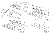
- Fig. 3 to 7 show stepwise how an inventive shelf element is assembled from the corresponding blanks. To increase clarity, only the most essential elements shown are provided with reference numerals.
- Fig. 3 shows the just spread blank for the walls of the shelf element.
- the blank 21 has as marked elements the rear wall 30 and the front wall 36.
- the openings 37 of the front wall 36 the material not required there is folded away. This can be folded for stabilization on the adjacent side walls and can also be fixed there.
- Fig. 4 shows how a blank 41, a shelf can be made.
- the upper narrower section 42 of the blank is folded down along the fold line between the cutouts for the slot 50.
- the result is a partially double-layered shelf with a single, continuous slot 50.
- Fig. 6 shows how now all shelves 40 are positioned flat against the back wall.
- the rear wall 30 is folded over on the front wall 36 back.
- a shelf element has arisen, which is generally cuboid and surrounded by four outer walls.
- Fig. 7 Looking at the rear wall and the second side wall 34. Inside shelves are now provided, which, however, are not visible here. They lie flat on the rear wall, so that the shelf member 20 is a total of a flat structure.
- Fig. 8 shows in perspective view a foldable shelf 10, which has four shelf elements. Visible is a first shelf element 20 and a second shelf element 22. Above the various shelf elements, a head part 12 is provided. This can, if provided by the head part 12 as upper edges of the shelf elements are used to stabilize the foldable shelf 10 in total. Mainly it serves as advertising space.
- the first shelf element 20 shows with its front wall 36 approximately to the viewer. It recognizes the openings 37a, 37b, 37c, 37d in the front wall, which are bounded at the bottom by transverse webs 38. The lowermost opening 37d is bounded at the bottom by a portion of the front wall which also serves as part of the base. In the first shelf member 20 find four shelves 40 place.
- the shelves are bounded to the right by the second side wall 34 of the first shelf member 20.
- the other side wall, the first side wall 32 of the first shelf element 20 is not visible in this arrangement.
- this first side wall 32 is completely covered by the second shelf element 22.
- the outwardly facing second side wall 34b and the front wall 36b of the second shelf element 22 can be seen.
- the left side of the front wall 36b of the second shelf element 22 shows the corresponding second side wall 34c of the next shelf element, namely the third shelf element 24.
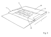
- the foldable shelf 10 in its folding arrangement.
- the foldable shelf 10 essentially forms a flat structure therein. Visible are the first shelf member 20 and the second shelf member 22.
- the shelf 10 is shown including the head portion 12, which can also be converted into a corresponding folding arrangement.
- This flat structure can be easily inserted into a package 60.
- the height h is small compared to the length of the side walls of the package 60.
- the height h is only one fifth, one tenth or one twentieth of the length I of the shortest side of the parallelepiped package 60 is. This is particularly advantageous for transport purposes.
- the packages 60 with the foldable shelves 10 can then be stacked particularly easily.
- the shelf not only offers a particularly convenient installation and folding into a convenient folding form, but also offers optimized shelves. These are optimized in particular for objects of rectangular cross-section.
- This is in the schematic drawing in the Fig. 10 particularly recognizable.
- this drawing which is a cross-sectional view on a vertical plane from the side, one can see on the left the front wall 36 of the shelf and on the right the rear wall 30 of the shelf.
- Between these walls of the shelf 40 is attached, which consists of a first layer of material from the section 42 and a second layer of material from the section 44.
- a slot 50 is designed as a breakthrough through both layers of material and receives the retaining lug 39, which is formed on the front wall 36.
- the opening 37 in the front wall ensures good access to the shelf 40.
- a glue 48 Adjoining the adhesive fold 48 is a bending region 46.
- This bending region 46 makes it possible to fold the shelf 40 onto the rear wall 30, but also to fold it away from the rear wall 30 and to transfer it into the use position shown here.
- the bending region 46 is provided in such a way that only one material layer, namely the material layer from the section 42, is present there. at suitably selected material, a sufficient flexibility in the bending region 46 can be ensured even by the choice of material.
- the bend can take place about the axis A running in the viewing direction. If corrugated board is used as material, one would orient the wave course parallel to the axis A.
- a Kinkfalz 52 is attached. This ensures that the shelf 40 is inclined and drops in over most of its surface from the front wall 36 to the rear wall 30 out.
- a small piece of the shelf, namely that located behind the buckling fold 52 on the back wall, is also oblique, but rises to the back wall.
- the kink caused by the kink 52 forms a convenient impulse.
- a rectangular object is shown by a dashed line. This can abut with its rear lower edge to the Kinkfalz 52. He is thereby brought to a predetermined position on the shelf 40. It when the slope of the shelf is just designed so that the object in this position with its rear upper edge just touches the shelf rear wall 30 is particularly favorable. This contact additionally supports the article on the shelf.
- the length of the shelf in particular its length between the nose 39 and the kink-fold 52, can be chosen so that the lower side of a rectangular object is just fitted between the kink-fold 52 and the nose 39. The over the shelf 40 upwardly projecting part of the nose 39 can then protect the object towards the front in addition to unwanted falling out.
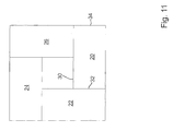
- Fig. 11 gives a schematic view of the foldable shelf from above.
- the foldable shelf 10 includes a first shelf member 20, a second shelf member 22, a third shelf member 24, and a fourth shelf member 26. These are arranged so that the back wall of a shelf member is partially covered by the first sidewall of the adjacent shelf member becomes. This leads to a total flush arrangement.
- the four rectangular shelf elements result in a total of a foldable shelf, which occupies a substantially square base. In the center of the foldable shelf 10, therefore, a cavity remains.
Landscapes
- Handcart (AREA)
- Display Racks (AREA)
- Making Paper Articles (AREA)
- Air Bags (AREA)
- Medicines Containing Plant Substances (AREA)
Abstract
Description
- Die vorliegende Erfindung betrifft ein faltbares Regal, welches aus mindestens einem Regalelement hergestellt werden kann. Dieses Regal ist auch zu einer Verwendung als Warenaufsteller in einem Verkaufraum geeignet. Solche Warenaufsteller findet man im Einzelhandel, etwa in Supermärkten, Drogeriemärkten und allgemein in Verkaufsräumen.
- Das
U.S.-Patent 4,311,100 offenbart einen Warenständer, der im Wesentlichen aus einem einteiligen Zuschnitt hergestellt werden kann. Das Material für die Böden wird aus dem im Übrigen für die Vorderseite bestimmten Teils des Zuschnitts herausgeklappt. Wenngleich dieser Ständer für viele Zwecke nützlich sein mag, erfordert eine Konstruktion ohne Vorderwand und ohne Abstützung von Regalböden etwa durch Querstege in der Vorderwand, die Verwendung eines relativ festen und damit kostspieligen Materials. Ferner erlauben die Böden keine besondere Anpassung an dort zu platzierenden Waren. Waren werden also nicht in besonderer Weise gehalten, so dass sie in einer idealen vorbestimmten Verkaufsposition angeboten werden können oder dass sie gegen ein Herausfallen nach vorne geschützt sind. Im Übrigen hat das gezeigte Regalelement teilweise offene Seitenwände. Diese Seitenwände, welche dreieckige offene Abschnitte aufweisen, sollen seitlichen Zugriff auf die Regalböden bieten. Diese Zugriffe sind wenig zweckmäßig, wenn solche Ständer miteinander zu einer größeren Regaleinheit verbunden werden sollen. - Die Patentanmeldung
WO 2007/148963 offenbart ein faltbares Warenregal. Dieses Regal wird aus relativ vielen einzelnen Teilen zusammengesetzt und wird in einer bevorzugten Ausführungsform mit einer mechanischen Entfaltungshilfe versehen. Im gefalteten Zustand des Regals wird die rechte und die linke Seitenwand einwärts gefaltet, also jeweils auf die Rückwand zu. Beim Entfalten des Regals bewegen sich beide Seitenwände in entgegengesetzter Richtung nach außen, das heißt, die linke Seitenwand klappt von der Rückwand weg nach links und die rechte Seitenwand klappt von der Rückwand weg nach rechts. Dieser Aufstellmechanismus führt dazu, dass man mehrere solche Regalteile nicht gut miteinander verbinden kann. Insbesondere wäre es unmöglich, Seitenwände benachbarter Regalteile miteinander zu verkleben, da dies den Aufstellmechanismus blockieren würde. - Die Offenlegungsschrift
DE 101 45 859 A1 offenbart ein klappbares Regalsystem. Dieses soll sich beispielsweise als CD-Regal oder Regal für Aktenordner anbieten. Die Wabenform der Regalelemente mag gut mit dem Faltmechanismus harmonieren, bedeutet aber bei der Lagerung von quaderförmigen Gegenständen eine gewisse Raumverschwendung. Auch sind Gegenstände nicht gegen das Herausfallen nach vorn gesichert. Es scheinen recht harte Regalböden und stabile Scharnier erforderlich zu sein, um den Faltmechanismus zu ermöglichen. - Das Gebrauchsmuster
DE G 87 13 942.1 offenbart ein Möbel aus Wellpappe oder ähnlichem faltbaren Material. Das Möbel soll ein nützliches Produkt aus Altpapier darstellen. Es kann insbesondere als Ordnungsmöbel mit Fächern und Schubladen dienen. Offenkundig ist allerdings, dass schon die Anfertigung der Vielzahl dargestellter Auszüge und Schubladen, die Fertigung und den Aufbau des Möbels kompliziert machen. - Die vorliegende Entwicklung strebt an, den Stand der Technik zu verbessern. Insbesondere soll preiswert ein stabiles Regal zur Verfügung gestellt werden. Dabei soll der Transport des erforderlichen Materials bequen sein und das Regal soll leicht durch eine ungeübte Privatperson oder ungeübtes Person aufzubauen sein. Ferner soll das Regal auch aus leichtem Material herstellbar sein. Dieses wird durch das Regal nach Anspruch 1 erreicht.
- Die vorliegende Erfindung betrifft ein faltbares Regal, welches aus mindestens einem Regalelement hergestellt werden kann. Insbesondere geht es um ein faltbares Regal, welches mindestens ein erstes Regalelement mit einer Rückwand, zwei Seitenwänden und einer teilweise durchbrochenen Vorderwand umfasst, welches ferner mindestens einen Regalboden umfasst, wobei der mindestens eine Regalboden beweglich mit der Rückwand verbunden ist und an der Vorderwand ein erstes Fixierungsmittel (beispielsweise Steckmittel) zur Fixierung des mindestens einen Regalbodens vorgesehen ist und ferner der mindestens eine Regalboden ein zweites Fixierungsmittel (beispielsweise Aufnahmen) zur Verbindung mit dem ersten Fixierungsmittel aufweist und das Regal von einer Faltanordnung, in der der mindestens eine Regalboden an der Rückwand anliegt und die Regalwände im Wesentlichen keinen Nutzraum einschließen, in eine Nutzanordnung überführt werden kann, in welcher der mindestens eine Regalboden mit dem ersten Fixierungsmittel, mit der Vorderwand verbunden ist und die Regalwände einen Nutzraum einschließen.
- Die Erfindung betrifft also ein faltbares Regal, welches mindestens ein erstes Regalelement umfasst. Das faltbare Regal kann durchaus auch mehrere Regalelemente umfassen. Beispielsweise könnte eine lineare Anordnung von drei oder vier Regalelementen als ein Regal angeboten werden. Dieses insbesondere dann, wenn die verschiedenen Elemente einen gemeinsamen Sockel oder einen gemeinsamen Kopfaufsatz haben.
- Das erste Regalelement, in der Regel aber auch alle weiteren Regalelemente sollen eine Rückwand, zwei Seitenwände und eine Vorderwand umfassen. Diese Wände können im Prinzip eine beliebige Form einschließen, in der Regel werden sie einen Quader einschließen.
- Die Vorderwand ist durchbrochen. Es sind also geeignete Durchbrüche vorzusehen, welche den Zugriff auf den Regalinnere erlauben.
- Ferner soll das erste Regalelement mindestens einen Regalboden umfassen. Dieser Regalboden ist beweglich mit der Rückwand verbunden. In alternativen, wenn auch weniger bevorzugten Ausführungen der Erfindung, ist es auch denkbar, dass der Regalboden mit einer anderen Wand, beispielsweise also einer der Seitenwände verbunden ist. Die Beweglichkeit des mindestens einen Regalbodens zur Rückwand soll so sein, dass der Regalboden in mindestens einer Position mit der Vorderwand verbunden und dort fixiert werden kann. Erfindungsgemäß weist die Vorderwand dazu erste und zweite Fixierungsmittel auf, welche zumindest vorzugsweise in der Form eines Steckmittels als erstes Fixierungsmittel und in der Form einer Aufnahme als korrespondierendes zweites Fixierungsmittel vorgesehen sind. Dabei ist die Aufnahme am oder im Regalboden vorgesehen.
- Die hierin beschriebenen Merkmales des mindestens einen Regalbodens sollen auch alle anderen Regalböden aufweisen, sofern eine Vielzahl von Regalböden vorgesehen ist. Ebenfalls gelten hierin für ein Regalelement gemacht Aussage auch für weitere Regalelemente eines faltbaren Regals.
- Das Regal und die Regalelemente sollen in eine Faltanordnung überführbar sein. In dieser Faltanordnung soll der mindestens eine Regalboden jedenfalls zu einem wesentlichen Teil an der Rückwand anliegen oder, sofern noch ein kleiner Abstand zwischen Rückwand und Regalboden verbleiben sollte, im Wesentlichen parallel zur Rückwand zu liegen kommen. Sofern mehrere Regalböden vorgesehen sind, sollen in der Faltanordnung diese sämtlich in diese Position zu bringen sein. In der Faltanordnung schließen die Regale und die Regalelemente keinen Nutzraum ein oder zumindest im Wesentlichen keinen Nutzraum. Wenn etwa Wände nicht ganz bündig aufeinander gefaltet werden, so mag ein geringer Raum verbleiben, der jedoch nicht als Nutzraum im Sinne eines Nutzraumes eines Regals zur Verfügung steht.
- Ferner sollen das Regal und die Regalelemente in eine Nutzanordnung überführt werden können. In dieser Nutzanordnung wird der Regalboden mit Hilfe der Fixierungsmittel, vorzugsweise also mit Hilfe des Steckmittels, welches die Vorderwand aufweist, mit der Vorderwand verbunden. Im Übrigen ist die Nutzanordnung eine, in der die Regalwände einen Nutzraum abschließen.
- Es hat sich günstig erwiesen, wenn der mindestens eine Regalboden in der Weise relativ zur Rückwand beweglich ist, dass er um eine Achse gekippt werden kann.
- Es hat sich als besonders zweckmäßig erwiesen, wenn die Beweglichkeit des Regalbodens und zwar insbesondere die Beweglichkeit des Regalbodens um eine Achse durch die Biegsamkeit des Materials hergestellt wird, aus welchem der mindestens eine Regalboden gefertigt wird. Der mindestens eine Regalboden kann durchaus aus mehreren verschiedenen Materialien bestehen. Es hat sich aber als möglich und vorteilhaft erwiesen, den Regalboden als Zuschnitt aus einer Materialbahn herzustellen. Dabei ist es auch möglich, diese Materialbahn so zu wählen, dass die erforderliche Biegsamkeit zur Verfügung gestellt wird.
- Die Materialbahn kann beispielsweise aus Kunststoff oder aus Pappe sein, insbesondere aus Kraftpappe oder Wellpappe. Dabei kann die Materialbahn Mantelzuschnitt einlagig oder ein Laminat sein.
- Insbesondere ist es möglich, einen Regalboden aus zwei Materiallagen zu erzeugen. Diese können beispielsweise zwei Materiallagen aus dem gleichen Zuschnitt aus der Materialbahn sein, wenn dieser gefaltet ist. Dabei können die beiden Materiallagen so angeordnet werden, dass ein Teil des Regalbodens nur aus einer Materiallage besteht und ein anderer Teil des Regalbodens aus zwei Materiallagen. Dabei kann dann die Achse, um die der Regalboden relativ zur Rückwand gekippt werden kann, in dem Teil des Bodens liegen, welcher aus einer Materiallage hergestellt ist. Die in der Regel höhere Biegsamkeit einer Materiallage im Vergleich zu einer doppelten Materiallage macht man sich so zunutze. Gleichzeitig kann man aber eine hinreichende Verstärkung des Regalbodens an anderen Stellen sicherstellen.
- Die Erfindung kann so ausgeführt werden, dass die Aufnahme des mindestens einen Regalbodens, welche zur Verbindung mit dem Steckmittel dient, als Schlitz ausgeführt ist. Ein solcher Schlitz kann eine nutartige Vertiefung im Regalboden sein oder kann alternativ und sogar vorzugsweise durch die ganze Tiefe des Regalbodens hindurch gehen, so dass eine schlitzförmige Öffnung entsteht.
- Es hat sich als günstig erwiesen, wenn die Vorderwand Querstege anbietet, die eine Auflage für den mindestens einen Regalboden, typischerweise also in einen vorderen Abschnitt des Regalbodens, liegen. Diese Querstege können beispielsweise die unteren Begrenzungen der Durchbrüche in der Vorderwand sein.
- Besonders zweckmäßig ist es, wenn die Querstege nach oben gerichtete Nasen aufweisen. Diese Nasen sind eine Form der ersten Fixierungsmittel und können von dem zweiten Fixierungsmittel, insbesondere also von den Schlitzen aufgenommen werden. Bei offenen Schlitzen ist es auch möglich, dass die Nasen durch den Schlitz hindurchragen und so an der Oberseite der Regalböden einen Überstand bilden. Ein solcher Überstand kann bewusst dazu eingesetzt werden, das Herausfallen von Gegenständen aus den Regalböden nach vorne zu vermeiden.
- Zu diesem Zweck kann es auch nützlich sein, den mindestens einen Regalboden schräg verlaufend anzuordnen, und zwar in der Form, dass er zumindest in einem Abschnitt von der Vorderwand zur Rückwand hin abfällt. Alternativ ist es natürlich auch möglich, den Regalboden eben vorzusehen. Nützlich ist ferner, wenn der mindestens eine Regalboden einen hinteren Anstoß aufweist. Ein im Regal platziertes Gut kann dann so platziert werden, dass es an dem Anstoß anliegt.
- Es ist auch möglich, das erfindungsgemäße Regale besonders auf darin zu platzierende Gegenstände abzustimmen. Insbesondere kann das Regal auf Gegenstände bestimmter Form, insbesondere bestimmten rechteckigen Querschnitts abgestimmt werden. Dabei kann es sowohl für verschiedene Gegenstände optimiert sein, als auch für Gegenstände identischen rechteckigen Querschnitts. Insbesondere kommt es in Betracht, dass ein Gegenstand rechteckigen Querschnitts, wenn er mit seiner hinteren unteren Kante am hinteren Anstoß anliegt, gerade mit seiner hinteren oberen Kante an die Rückwand stößt. Dieses führt dazu, dass der Gegenstand hinten an zwei Punkten gestützt wird. Folglich steht der Gegenstand stabil im Regal und findet im Regal eine klar vordefinierte Position.
- Das Regal ist daher besonders auch zur Präsentation und Lagerung von Büchern, beispielsweise auch Taschenbüchern, und Ton- und Bildträgern, wie CD's, Videokassetten und DVD's geeignet. Daher kann es neben dem Einsatz in Privaträumen, auch gut im Verkaufsraum einer Buchhandlung oder einer Videothek Einsatz finden.
- Ein erfindungsgemäßes faltbares Regal kann beispielsweise zwei, drei, vier, fünf oder sechs Regalelemente umfassen. In vielen Situationen ist ein faltbares Regal, welches vier Regalelemente umfasst, besonders zweckmäßig. Dabei kann es insbesondere zweckmäßig sein, die vier Regalelemente zu einem Rechteck oder Quadrat anzuordnen. Vorzugsweise geschieht dies so, dass die Vorderwände der entsprechenden Regalelemente in der Aufsicht ein Rechteck oder Quadrat beschreiben.
- Besonders nützlich ist ein faltbares Regal, welches eine flache Faltposition einnehmen kann. Dabei ist es sehr nützlich, wenn das faltbare Regal in einer quaderförmigen Umverpackung platziert werden kann, deren Höhe deutlich geringer ist als die Länge ihrer kürzesten Seite. Vorzugsweise beträgt diese Höhe nur ein Zehntel oder weniger als die Länge der kürzesten Seite.
- In einem weiteren Aspekt betrifft die Erfindung auch ein Verfahren zum Aufstellen eines faltbaren Regals. Dieses Verfahren umfasst mindestens folgende Schritte (a) Ausüben von Druck auf zwei gegenüberliegende Kanten des faltbaren Regals; (b) Herunterklappen des mindestens einen Regalbodens ; (c) Fixieren des mindestens einen Regalbodens mit Hilfe des Steckmittels und der Aufnahme zur Verbindung mit dem Steckmittel.
- Dieser Schritte werden vorzugsweise in dieser Reihenfolgen ausgeführt. Das Verfahren kann ferner auch vor Schritt (a) das Entnehmen eines des faltbaren Regals aus einer quaderförmigen Umverpackung umfassen.
- Weitere Merkmale, aber auch Vorteile der Erfindung ergeben sich aus den nachfolgend aufgeführten Zeichnungen und der zugehörigen Beschreibung. In den Abbildungen und in den dazugehörigen Beschreibungen sind Merkmale der Erfindung in Kombination beschrieben. Diese Merkmale können allerdings auch in anderen Kombinationen von einem erfindungsgemäßen Gegenstand umfasst werden. Jedes offenbarte Merkmal ist also auch als in technisch sinnvollen Kombinationen mit anderen Merkmalen offenbart zu betrachten. Bei den Abbildungen zeigen:
- Fig. 1
- einen Zuschnitt für die Wände eines erfindungsgemäßen Regalelements
- Fig. 2
- einen Zuschnitt für einen Regalboden
- Fig. 3
- einen ersten Schritt bei der Fertigung des Regalelementes aus dem Zuschnitt
- Fig. 4
- zeigt als einen weiteren Schritt die Zusammenfügung des Regalbodens aus dem Zuschnitt
- Fig. 5
- zeigt als einen weiteren Schritt die Verbindung der Regalböden mit der Außenhülle des Regalelementes
- Fig.6
- zeigt einen weiteren Schritt beim Zusammensetzen des Regalelementes
- Fig. 7
- zeigt ein fertig zusammengesetztes Regalelement
- Fig. 8
- zeigt in dreidimensionaler Ansicht ein faltbares Regal, welches vier Regalelemente umfasst und in seine Nutzanordnung überführt ist
- Fig. 9
- zeigt ein faltbares Regal mit vier Regelelementen in der Faltanordnung und teilweise von einer Verpackung umschlossen
- Fig. 10
- zeigt einen teilweise schematischen Querschnitt durch ein Regalelement und einen Regalboden in einer vertikalen Ebene
- Fig. 11
- zeigt auf eine schematische Aufsicht auf ein faltbares Regal, welches vier Regalelement umfasst
-
Fig. 1 zeigt zunächst einen Zuschnitt 12, aus welchem im Wesentlichen die Wände eines erfindungsgemäßen Regalelementes hergestellt werden können. Aus dem linken Abschnitt des Zuschnitts entsteht die Rückwand 30, aus dem anschließenden schmaleren Abschnitt entsteht die zweite Seitenwand 34 aus dem anschließendem Abschnitt entsteht die Vorderwand 36 und aus dem daran anschließenden Abschnitt entsteht die erste Seitenwand 32. Besonders materialsparend ist die Verwendung rechteckiger Zuschnitte und somit auch die Herstellung rechteckiger Seitenwände und entsprechender quaderförmiger Regalelemente. Der Zuschnitt weist seitliche Laschen auf, welche nicht näher bezeichnet sind und in weitgehend beliebiger zweckmäßiger Weise gestaltet werden können. Insbesondere sind Stecklaschen zweckmäßig oder auch Klebelaschen, welche z. B. Klebeflächen tragen können. Die Vorderwand 36 weist Durchbrüche 37 auf. Insgesamt sind in diesem Zuschnitt vier Durchbrüche vorgesehen, nämlich die Durchbrüche 37a, 37b, 37c und 37d. Nach unten hin wird jeder Durchbruch von einem Quersteg begrenzt. Dabei sind die oberen drei Querstege schmaler als der unterste, welcher zugleich als Art Sockelelement dient. Die Bereiche, welche als Durchbrüche 37 vorgesehen sind, sind in dieser Ansicht noch mit Material gefüllt. Jedoch sind Schnitte so vorgesehen, dass die Durchbrüche 37 geöffnet werden können. Die genaue Weise in der dies geschieht, wird im Zusammenhang mit den nachfolgenden Abbildungen noch erläutert, insbesondere mitFig. 3 . -
Fig. 2 zeigt einen Zuschnitt 41, aus dem ein Regalboden 40 hergestellt werden kann. Dieser Zuschnitt ist nach oben hin verjüngt und weist zwischen dem mit 42 und dem mit 44 markierten Abschnitt eine Falzlinie auf. Der Abschnitt 44 ist kürzer als der Abschnitt 42. Beim Umlegen um diese Falzlinie kann also der Abschnitt 44 auf den Abschnitt 42 aufgelegt werden. Dabei entsteht ein im ganzen Bereich des Abschnitts 44 zweilagiger Regalboden. Jedoch ist der Regalboden im unteren Bereich des Abschnitts 42 noch einlagig. Dieser einlagige Bereich umfasst die Verbindunglasche 48 (allerdings auch noch einen darüber hinausragenden Bereich). Auf der Verbindungslasche 48 ist ein Klebebalken 49 vorgesehen. - Man erkennt ferner zwei Bereiche, in denen Ausstanzungen für Schlitze vorgesehen sind, nämlich den Bereich 50a und 50b. Nach dem Ausstanzen des Materials und dem Übereinanderlegen der Abschnitte 42 und 44 entsteht hier ein einheitlicher Schlitz 50. Ferner erkennbar ist die Knicklinie 52, an welcher der Regalboden 40 abgeknickt werden kann. Parallel zur Knicklinie 52 ist oberhalb von dieser ein Klebebalken 54 vorgesehen, mit dem die Abschnitte 42 und 44 des Regalbodens 40 aufeinander fixiert werden können. Die nachfolgend näher beschriebene
Fig. 4 erläutert diesen Vorgang noch einmal anschaulich. - Die
Fig. 3 bis 7 zeigen schrittweise, wie ein erfindungsgemäßes Regalelement aus den entsprechenden Zuschnitten zusammengesetzt wird. Zur Erhöhung der Übersichtlichkeit sind nur die wesentlichsten dargestellten Elemente mit Bezugszeichen versehen. -
Fig. 3 zeigt den eben ausgebreiteten Zuschnitt für die Wände des Regalelementes. Der Zuschnitt 21 weist als markestete Elemente die Rückwand 30 und die Vorderwand 36 auf. In einem frühen Aufbauschritt wird aus den Durchbrüchen 37 der Vorderwand 36 das dort nicht erforderliche Material weggeklappt. Dieses kann zur Stabilisierung auf die angrenzenden Seitenwände gefaltet werden und kann dort auch noch fixiert werden. -
Fig. 4 zeigt wie aus einem Zuschnitt 41 ein Regalboden hergestellt werden kann. Dazu wird das obere schmalere Abschnitt 42 des Zuschnitts entlang der Falzlinie zwischen den Ausstanzungen für den Schlitz 50 umgeklappt. So entsteht ein teilweise doppellagiger Regalboden mit einem einheitlichen, durchgehender Schlitz 50. - In
Fig. 5 sieht man wie vier in der inFig. 4 gezeigten Weise vorbereitete Böden mit der Rückwand 30 des Zuschnitts 21 verbunden werden. Dazu bedient sich der Klebelaschen 48 und ihrer Klebebalken 49. -
Fig. 6 zeigt wie nun alle Regalböden 40 flach auf der Rückwand anliegend positioniert sind. Die Rückwand 30 wird so auf die Vorderwand 36 hin umgeklappt. - Dieser Prozess ist in
Fig. 7 vollendet. Dadurch ist ein Regalelement entstanden, welches insgesamt quaderförmig ist und von vier Außenwänden umgeben. InFig. 7 schaut man auf die Rückwand und die zweite Seitenwand 34. Innen sind nun Regalböden vorgesehen, welche jedoch hier nicht sichtbar sind. Sie liegen flach auf der Rückwand an, so dass das Regalelement 20 insgesamt ein flächiges Gebilde darstellt. -
Fig. 8 zeigt in perspektivischer Ansicht ein faltbares Regal 10, welches vier Regalelemente aufweist. Sichtbar ist ein erstes Regalelement 20 und ein zweites Regalelement 22. Oberhalb der verschiedenen Regalelemente ist ein Kopfteil 12 vorgesehen. Dieses kann, sofern von dem Kopfteil 12 etwa Oberkanten der Regalelemente umschlossen werden, zur Stabilisierung des faltbaren Regals 10 insgesamt dienen. Hauptsächlich dient es jedoch als Werbefläche. Das erste Regalelement 20 zeigt mit seiner Vorderwand 36 ungefähr zum Betrachter. Man erkannt die Durchbrüche 37a, 37b, 37c, 37d in der Vorderwand, welche nach unten hin durch Querstege 38 begrenzt werden. Der unterste Durchbruch 37d wird nach unten hin durch einen Teil der Vorderwand begrenzt, der auch als Teil des Sockels dient. In dem ersten Regalelement 20 finden vier Regalböden 40 Platz. Die Regalböden werden nach rechts durch die zweite Seitenwand 34 des ersten Regalelements 20 begrenzt. Die andere Seitenwand, die erste Seitenwand 32 des ersten Regalelements 20 ist in dieser Anordnung nicht sichtbar. Um die Anordnung kompakter zu machen, ist diese erste Seitenwand 32 vollständig durch das zweite Regalelement 22 verdeckt. Beim zweiten Regalelement erkennt man die nach außen weisende zweite Seitenwand 34b, sowie die Vorderwand 36b des zweiten Regalelementes 22. Links anschließend an die Vorderwand 36b des zweiten Regalelements 22 erkennt man die entsprechende zweite Seitenwand 34c des nächsten Regalelements, nämlich des dritten Regalelements 24. - In
Fig. 9 erkennt man das faltbare Regal 10 in seiner Faltanordnung. Das faltbare Regal 10 bildet darin im Wesentlichen ein flächiges Gebilde. Sichtbar sind das erste Regalelement 20 und das zweite Regalelement 22. Das Regal 10 ist einschließlich des Kopfteils 12 dargestellt, welches ebenfalls in eine korrespondierende Faltanordnung überführt werden kann. Dieses flächige Gebilde kann bequem in eine Verpackung 60 eingeschoben werden. Dabei kommt, wie abgebildet, im Wesentlichen eine flache quaderförmige Verpackung in Betracht. Insbesondere ist es möglich, dass die Höhe h klein ist im Vergleich zur Länge der Seitenwände der Verpackung 60. Insbesondere kommt es in Betracht, dass die Höhe h nur ein Fünftel, ein Zehntel oder ein Zwanzigstel der Länge I der kürzesten Seite der quaderförmigen Verpackung 60 beträgt. Dieses ist zu Transportzwecken besonders vorteilhaft. Beispielsweise können die Verpackungen 60 mit den faltbaren Regalen 10 dann besonders leicht gestapelt werden. - Das Regal bietet nicht nur eine besonders bequeme Aufstellung und ein Zusammenfalten in eine günstige Faltform, sondern bietet auch optimierte Regalböden an. Diese sind insbesondere für Gegenstände rechteckigen Querschnitts optimiert. Dieses ist in der schematischen Zeichnung in der
Fig. 10 besonders gut erkennbar. In dieser Zeichnung, welche eine Querschnittsansicht auf eine vertikale Ebene von der Seite darstellt, erkennt man links die Vorderwand 36 des Regals und rechts die Rückwand 30 des Regals. Zwischen diesen Wänden ist der Regalboden 40 angebracht, der aus einer ersten Materiallage aus dem Abschnitt 42 und einer zweiten Materiallage aus dem Abschnitt 44 besteht. Ein Schlitz 50 ist als Durchbruch durch beide Materiallagen gestaltet und nimmt die Haltenase 39 auf, welche an der Vorderwand 36 ausgebildet ist. Der Durchbruch 37 in der Vorderwand stellt den guten Zugriff auf den Regalboden 40 sicher. An seiner rückwärtigen Seite ist der Regalboden 40 durch einen Klebefalz 48 mit der Rückwand 30 verbunden. An den Klebefalz 48 schließt sich ein Biegebereich 46 an. Dieser Biegebereich 46 erlaubt es, den Regalboden 40 auf die Rückwand 30 zu falten, ihn aber auch von der Rückwand 30 weg zu falten und in die hier abgebildete Nutzstellung zu überführen. Der Biegebereich 46 ist dabei so vorgesehen, dass dort nur eine Materiallage, nämlich die Materiallage aus dem Abschnitt 42 vorhanden ist. Bei geeignet gewähltem Material, kann eine hinreichende Biegbarkeit im Biegebereich 46 schon durch die Materialwahl sichergestellt werden. Die Biegung kann um die in Blickrichtung verlaufende Achse A erfolgen. Wenn Wellpappe als Material eingesetzt wird, würde man den Wellenverlauf parallel zu der Achse A orientieren. - Etwa im hinteren Drittel des Regalbodens 40 ist ein Knickfalz 52 angebracht. Diese sorgt dafür, dass der Regalboden 40 schräg verläuft und in über den größten Teil seiner Fläche von der Vorderwand 36 zur Rückwand 30 hin abfällt. Ein kleines Stück des Regalbodens, nämlich das hinter der Knickfalz 52 auf die Rückwand zu gelegene, ist ebenfalls schräg, steigt aber zur Rückwand hin an. Der durch die Knickfalz 52 erzeugte Knick bildet einen zweckmäßigen Anstoß.
- Schematisch ist durch eine gestrichelte Linie ein rechteckiger Gegenstand dargestellt. Dieser kann mit seiner hinteren unteren Kante an die Knickfalz 52 anstoßen. Er wird dadurch in eine vorgegebene Position auf dem Regalboden 40 gebracht. Besonders günstig ist es, wenn die Schräge des Regalbodens gerade so ausgelegt ist, dass der Gegenstand in dieser Position mit seiner hinteren oberen Kante gerade die Regalrückwand 30 berührt. Dieser Kontakt stützt den Gegenstand im Regal dann zusätzlich ab. Die Länge des Regalbodens, insbesondere seine Länge zwischen der Nase 39 und der Knickfalz 52, kann so gewählt werden, dass die untere Seite eines rechteckigen Gegenstandes gerade zwischen dem Knickfalz 52 und der Nase 39 eingepasst ist. Der über den Regalboden 40 nach oben überstehende Teil der Nase 39 kann dann den Gegenstand nach vorne hin zusätzlich gegen ungewolltes Herausfallen schützen.
-
Fig. 11 gibt eine schematische Ansicht des faltbaren Regals von oben. Das faltbare Regal 10 umfasst ein erstes Regalelement 20, ein zweites Regalelement 22, ein drittes Regalelement 24 und ein viertes Regalelement 26. Diese sind so angeordnet, dass die Rückwand eines Regalelements jeweils zum Teil von der ersten Seitenwand des angrenzenden Regalelements bedeckt wird. Dies führt insgesamt zu einer bündigen Anordnung. Die vier rechteckigen Regalelemente ergeben insgesamt ein faltbares Regal, welches eine im Wesentlichen quadratische Grundfläche einnimmt. Im Zentrum des faltbaren Regals 10 verbleibt daher ein Hohlraum. - Die Beschreibung hat gezeigt, wie erfindungsgemäß in einfacher Weise ein leicht faltbares und gut aufstellbares Regal erzeugt werden kann. In diesem lassen sich insbesondere Gegenstände des rechteckigen Querschnitts optimal anordnen.
-
- 10
- Faltbares Regal
- 12
- Kopfteil
- 20
- Erstes Regalelement
- 22
- Zweites Regalelement
- 24
- Drittes Regalelement
- 26
- Viertes Regalelement
- 30
- Rückwand
- 32
- Erste Seitenwand
- 34
- Zweite Seitenwand
- 36
- Vorderwand
- 37
- Durchbruch (37a, 37b, 37c, 37d)
- 38
- Querstege (38a, 38b, 38c, 38d)
- 39
- Nase
- 40
- Regalboden
- 42
- Erster Abschnitt
- 44
- Zweiter Abschnitt
- 46
- Biegebereich
- 48
- Verbindungslasche
- 49
- Klebebalken
- 50
- Schlitz (50a Oberseite, 50b Unterseite)
- 52
- Knickfalz
- 54
- Innerer Klebebalken
- 60
- Verpackung
- h
- Höhe der Verpackung
- l
- Länge der kürzeren Seite der Verpackung
Claims (14)
- Faltbares Regal (10), welches mindestens ein erstes Regalelement (20) mit einer Rückwand (30), zwei Seitenwänden (32, 34) und einer teilweise durchbrochenen Vorderwand (36) umfasst, welches ferner mindestens einen Regalboden (40) umfasst, dadurch gekennzeichnet, dass der mindestens eine Regalboden (40) beweglich mit der Rückwand (30) verbunden ist und an der Vorderwand (36) ein erstes Fixierungsmittel (39) zur Fixierung des mindestens einen Regalbodens (40) vorgesehen ist und ferner der mindestens eine Regalboden (40) ein zweites Fixierungsmittel (50) zur Verbindung mit dem ersten Fixierungsmittel (39) aufweist und das Regal (10) von einer Faltanordnung, in der der mindestens eine Regalboden (40) an der Rückwand (30) anliegt und die Regalwände (30, 32, 34, 36) im Wesentlichen keinen Nutzraum einschließen, in eine Nutzanordnung überführt werden kann, in welcher der mindestens eine Regalboden (40) mit dem ersten Fixierungsmittel (39), mit der Vorderwand (36) verbunden ist und die Regalwände einen Nutzraum einschließen.
- Faltbares Regal (10) nach Anspruch 1, bei dem der mindestens eine Regalboden (40) relativ zur Rückwand (30) um eine Achse (A) gekippt werden kann.
- Faltbares Regal (10) nach einem der Ansprüche 1 oder 2, bei dem die Beweglichkeit des Regalbodens (40) um diese Achse (A) durch die Biegsamkeit des Materials, aus dem der mindestens eine Regalboden (40) gefertigt wird, gegeben ist.
- Faltbares Regal (10) nach einem der vorhergehenden Ansprüche, bei dem ein Teil des mindestens einen Regalbodens (40) aus zwei Materiallagen (42, 44) und ein Teil des Regalbodens (40) aus nur einer Materiallage (42) hergestellt ist und die Achse (A), um die der mindestens eine Boden relativ zur Rückwand (30) bewegt werden kann, in dem Teil des Bodens liegt, der aus einer Materiallage (42) hergestellt ist.
- Faltbares Regal (10) nach einem der vorhergehenden Ansprüche, bei dem das zweite Fixierungsmittel des mindestens einen Regalbodens (40) zur Verbindung mit dem ersten Fixierungsmittel (39) als Schlitz (50) ausgeführt ist.
- Faltbares Regal (10) nach einem der vorhergehenden Ansprüche, bei dem die Vorderwand (36) einen Quersteg (38) zur Auflage des mindestens einen Regalbodens (40) aufweist.
- Faltbares Regal (10) nach dem Anspruch 6, bei dem die Oberseite des Quersteges (38) eine nach oben gerichtete Nase (39) aufweist, welche von dem zweiten Fixierungsmittel, beispielsweise dem Schlitz (50), aufgenommen werden kann.
- Faltbares Regal (10) nach einem der vorhergehenden Ansprüche, bei dem zumindest ein Abschnitt des mindestens einen Regalbodens (40) schräg, und von der Vorderwand (36) zur Rückwand (30) hin abfallend angeordnet ist.
- Faltbares Regal (10) nach einem der vorhergehenden Ansprüche, bei dem der mindestens eine Regalboden (40) einen hinteren Anstoß (52) aufweist, gegen den anliegend ein im Regal stehendes Gut platziert werden kann.
- Faltbares Regal (10) nach dem Anspruch 9, welches insbesondere für Gegenstände eines bestimmten rechteckigen Querschnitts ausgelegt ist und bei dem der mindestens eine Regalboden (40) so ausgelegt ist, dass ein Gegenstand rechteckigen Querschnitts, wenn er mit der hinteren unteren Kante am Anstoß (52) anliegt, mit seiner hinteren oberen Kante gegen die Rückwand (30) stößt.
- Faltbares Regal (10), welches vier Regalelemente (20, 22, 24, 26) umfasst.
- Faltbares Regal (10) nach dem Anspruch 11, bei welchem die Vorderwände (36a, 36b, 36c, 36d) der vier Regalelemente (22, 24, 26, 28) in einem Rechteck angeordnet sind.
- Faltbares Regal (10) nach einem der vorhergehenden Ansprüche, welches in einer quaderförmigen Verpackung (60) platziert werden kann, deren Höhe (h) nur ein Zehntel oder weniger beträgt als die Länge seiner kürzesten Seite (I).
- Verfahren zum Aufstellen eines faltbaren Regals, welches folgende Schritte umfasst:- Ausüben von Druck auf zwei gegenüberliegende Kanten des faltbaren Regals (10),- Herunterklappen des mindestens einen Regalbodens (40)- Fixieren des mindestens einen Regalbodens mit Hilfe des Steckmittels (39) und der Aufnahme (50) zur Verbindung mit dem Steckmittel (39)
Priority Applications (3)
| Application Number | Priority Date | Filing Date | Title |
|---|---|---|---|
| PL09164259T PL2281479T3 (pl) | 2009-06-30 | 2009-06-30 | Półka składana |
| AT09164259T ATE511775T1 (de) | 2009-06-30 | 2009-06-30 | Faltbares regal |
| EP09164259A EP2281479B1 (de) | 2009-06-30 | 2009-06-30 | Faltbares Regal |
Applications Claiming Priority (1)
| Application Number | Priority Date | Filing Date | Title |
|---|---|---|---|
| EP09164259A EP2281479B1 (de) | 2009-06-30 | 2009-06-30 | Faltbares Regal |
Publications (2)
| Publication Number | Publication Date |
|---|---|
| EP2281479A1 true EP2281479A1 (de) | 2011-02-09 |
| EP2281479B1 EP2281479B1 (de) | 2011-06-08 |
Family
ID=41381807
Family Applications (1)
| Application Number | Title | Priority Date | Filing Date |
|---|---|---|---|
| EP09164259A Active EP2281479B1 (de) | 2009-06-30 | 2009-06-30 | Faltbares Regal |
Country Status (3)
| Country | Link |
|---|---|
| EP (1) | EP2281479B1 (de) |
| AT (1) | ATE511775T1 (de) |
| PL (1) | PL2281479T3 (de) |
Citations (9)
| Publication number | Priority date | Publication date | Assignee | Title |
|---|---|---|---|---|
| US4311100A (en) | 1979-10-29 | 1982-01-19 | Container Corporation Of America | Multi-shelf display stand |
| DE8713942U1 (de) | 1987-10-15 | 1988-02-25 | Stange, Hans-Peter, 1000 Berlin | Möbel aus Wellpappe oder ähnlichem faltbaren Material |
| US4785944A (en) * | 1987-08-24 | 1988-11-22 | Thomson-Leeds Company, Inc. | Collapsible display and dispensing device |
| DE10145859A1 (de) | 2001-09-14 | 2003-04-03 | Frank Schneider | Klappbares Regalsystem |
| US20050274684A1 (en) * | 2004-06-08 | 2005-12-15 | Swanson John L | Method and apparatus for a collapsible multi-compartment storage and display center |
| WO2007148963A2 (en) | 2006-06-20 | 2007-12-27 | Smurfit Kappa Zedek B.V. | Fold-flat display unit |
| US20080169340A1 (en) * | 2007-01-12 | 2008-07-17 | Sheffer Phil B | Folded and glued display container having shelf elements |
| US20080265726A1 (en) * | 2007-04-25 | 2008-10-30 | Sheffer Phil B | Folded and glued display container having integral shelf elements |
| EP2030536A2 (de) * | 2007-08-29 | 2009-03-04 | Plastotech S.r.l. | Schaukasten |
-
2009
- 2009-06-30 AT AT09164259T patent/ATE511775T1/de active
- 2009-06-30 PL PL09164259T patent/PL2281479T3/pl unknown
- 2009-06-30 EP EP09164259A patent/EP2281479B1/de active Active
Patent Citations (9)
| Publication number | Priority date | Publication date | Assignee | Title |
|---|---|---|---|---|
| US4311100A (en) | 1979-10-29 | 1982-01-19 | Container Corporation Of America | Multi-shelf display stand |
| US4785944A (en) * | 1987-08-24 | 1988-11-22 | Thomson-Leeds Company, Inc. | Collapsible display and dispensing device |
| DE8713942U1 (de) | 1987-10-15 | 1988-02-25 | Stange, Hans-Peter, 1000 Berlin | Möbel aus Wellpappe oder ähnlichem faltbaren Material |
| DE10145859A1 (de) | 2001-09-14 | 2003-04-03 | Frank Schneider | Klappbares Regalsystem |
| US20050274684A1 (en) * | 2004-06-08 | 2005-12-15 | Swanson John L | Method and apparatus for a collapsible multi-compartment storage and display center |
| WO2007148963A2 (en) | 2006-06-20 | 2007-12-27 | Smurfit Kappa Zedek B.V. | Fold-flat display unit |
| US20080169340A1 (en) * | 2007-01-12 | 2008-07-17 | Sheffer Phil B | Folded and glued display container having shelf elements |
| US20080265726A1 (en) * | 2007-04-25 | 2008-10-30 | Sheffer Phil B | Folded and glued display container having integral shelf elements |
| EP2030536A2 (de) * | 2007-08-29 | 2009-03-04 | Plastotech S.r.l. | Schaukasten |
Also Published As
| Publication number | Publication date |
|---|---|
| EP2281479B1 (de) | 2011-06-08 |
| PL2281479T3 (pl) | 2011-10-31 |
| ATE511775T1 (de) | 2011-06-15 |
Similar Documents
| Publication | Publication Date | Title |
|---|---|---|
| EP1459650B1 (de) | Regal aus einem knickbaren Material wie Pappe | |
| EP2255703B1 (de) | Auffaltbarer Warenaufsteller | |
| DE102008023619B4 (de) | Regaldisplay | |
| DE102013001415B4 (de) | Regal aus einem knickbaren flächigen Material wie Pappe oder Wellpappe | |
| EP2604146B1 (de) | Regal | |
| AT522769B1 (de) | Faltkiste | |
| EP4620355A1 (de) | Warendisplay und verfahren zu dessen herstellung | |
| EP2281479B1 (de) | Faltbares Regal | |
| EP2253249A1 (de) | System von Warenaufstellern | |
| DE202007001005U1 (de) | Verkaufsmodul und Display-Set | |
| DE102018132416B4 (de) | Regalträger für ein offenes Regal | |
| DE102012025017B4 (de) | Warenständer | |
| DE202020106165U1 (de) | Stapelbarer Warenträger | |
| DE202006013260U1 (de) | Display-Verkaufsverpackung | |
| EP0423754B1 (de) | Versand- und Verkaufsbehälter | |
| DE9206621U1 (de) | Regal aus Pappe | |
| EP2233048B1 (de) | Offenes Display-System | |
| DE202006009756U1 (de) | Verkaufsmodul, Display-Set und Zuschnitt-Set | |
| DE102009007147B4 (de) | Einteiliger Zuschnitt für eine Displayverpackung und mit dem Zuschnitt hergestellte Displayverpackung | |
| DE9205177U1 (de) | Obst- oder Gemüsekiste | |
| DE2520551A1 (de) | Dekorations- und regalsystem | |
| DE102008029217B4 (de) | Trayverpackung, insbesondere für schwere Produkte | |
| DE202011003175U1 (de) | Regal | |
| DE102005010192B4 (de) | Regalartig stapelbare Verpackungseinheit für Flaschen | |
| DE19728477A1 (de) | Behälterzuschnitt zur Herstellung eines Behälters |
Legal Events
| Date | Code | Title | Description |
|---|---|---|---|
| PUAI | Public reference made under article 153(3) epc to a published international application that has entered the european phase |
Free format text: ORIGINAL CODE: 0009012 |
|
| GRAP | Despatch of communication of intention to grant a patent |
Free format text: ORIGINAL CODE: EPIDOSNIGR1 |
|
| 17P | Request for examination filed |
Effective date: 20100721 |
|
| AK | Designated contracting states |
Kind code of ref document: A1 Designated state(s): AT BE BG CH CY CZ DE DK EE ES FI FR GB GR HR HU IE IS IT LI LT LU LV MC MK MT NL NO PL PT RO SE SI SK TR |
|
| AX | Request for extension of the european patent |
Extension state: AL BA RS |
|
| RIC1 | Information provided on ipc code assigned before grant |
Ipc: A47F 5/11 20060101ALI20110125BHEP Ipc: A47B 43/02 20060101AFI20110125BHEP Ipc: A47B 55/06 20060101ALI20110125BHEP |
|
| GRAS | Grant fee paid |
Free format text: ORIGINAL CODE: EPIDOSNIGR3 |
|
| GRAA | (expected) grant |
Free format text: ORIGINAL CODE: 0009210 |
|
| AK | Designated contracting states |
Kind code of ref document: B1 Designated state(s): AT BE BG CH CY CZ DE DK EE ES FI FR GB GR HR HU IE IS IT LI LT LU LV MC MK MT NL NO PL PT RO SE SI SK TR |
|
| REG | Reference to a national code |
Ref country code: GB Ref legal event code: FG4D Free format text: NOT ENGLISH |
|
| REG | Reference to a national code |
Ref country code: CH Ref legal event code: EP |
|
| REG | Reference to a national code |
Ref country code: IE Ref legal event code: FG4D Free format text: LANGUAGE OF EP DOCUMENT: GERMAN |
|
| REG | Reference to a national code |
Ref country code: DE Ref legal event code: R096 Ref document number: 502009000757 Country of ref document: DE Effective date: 20110721 |
|
| REG | Reference to a national code |
Ref country code: CH Ref legal event code: NV Representative=s name: PATENTANWAELTE SCHAAD, BALASS, MENZL & PARTNER AG |
|
| REG | Reference to a national code |
Ref country code: NL Ref legal event code: VDEP Effective date: 20110608 |
|
| PG25 | Lapsed in a contracting state [announced via postgrant information from national office to epo] |
Ref country code: SE Free format text: LAPSE BECAUSE OF FAILURE TO SUBMIT A TRANSLATION OF THE DESCRIPTION OR TO PAY THE FEE WITHIN THE PRESCRIBED TIME-LIMIT Effective date: 20110608 Ref country code: NO Free format text: LAPSE BECAUSE OF FAILURE TO SUBMIT A TRANSLATION OF THE DESCRIPTION OR TO PAY THE FEE WITHIN THE PRESCRIBED TIME-LIMIT Effective date: 20110908 Ref country code: LT Free format text: LAPSE BECAUSE OF FAILURE TO SUBMIT A TRANSLATION OF THE DESCRIPTION OR TO PAY THE FEE WITHIN THE PRESCRIBED TIME-LIMIT Effective date: 20110608 Ref country code: HR Free format text: LAPSE BECAUSE OF FAILURE TO SUBMIT A TRANSLATION OF THE DESCRIPTION OR TO PAY THE FEE WITHIN THE PRESCRIBED TIME-LIMIT Effective date: 20110608 |
|
| REG | Reference to a national code |
Ref country code: PL Ref legal event code: T3 |
|
| PG25 | Lapsed in a contracting state [announced via postgrant information from national office to epo] |
Ref country code: GR Free format text: LAPSE BECAUSE OF FAILURE TO SUBMIT A TRANSLATION OF THE DESCRIPTION OR TO PAY THE FEE WITHIN THE PRESCRIBED TIME-LIMIT Effective date: 20110909 Ref country code: ES Free format text: LAPSE BECAUSE OF FAILURE TO SUBMIT A TRANSLATION OF THE DESCRIPTION OR TO PAY THE FEE WITHIN THE PRESCRIBED TIME-LIMIT Effective date: 20110919 Ref country code: CY Free format text: LAPSE BECAUSE OF FAILURE TO SUBMIT A TRANSLATION OF THE DESCRIPTION OR TO PAY THE FEE WITHIN THE PRESCRIBED TIME-LIMIT Effective date: 20110608 Ref country code: LV Free format text: LAPSE BECAUSE OF FAILURE TO SUBMIT A TRANSLATION OF THE DESCRIPTION OR TO PAY THE FEE WITHIN THE PRESCRIBED TIME-LIMIT Effective date: 20110608 Ref country code: SI Free format text: LAPSE BECAUSE OF FAILURE TO SUBMIT A TRANSLATION OF THE DESCRIPTION OR TO PAY THE FEE WITHIN THE PRESCRIBED TIME-LIMIT Effective date: 20110608 Ref country code: FI Free format text: LAPSE BECAUSE OF FAILURE TO SUBMIT A TRANSLATION OF THE DESCRIPTION OR TO PAY THE FEE WITHIN THE PRESCRIBED TIME-LIMIT Effective date: 20110608 |
|
| REG | Reference to a national code |
Ref country code: HU Ref legal event code: AG4A Ref document number: E011962 Country of ref document: HU |
|
| PG25 | Lapsed in a contracting state [announced via postgrant information from national office to epo] |
Ref country code: MT Free format text: LAPSE BECAUSE OF FAILURE TO SUBMIT A TRANSLATION OF THE DESCRIPTION OR TO PAY THE FEE WITHIN THE PRESCRIBED TIME-LIMIT Effective date: 20110608 Ref country code: NL Free format text: LAPSE BECAUSE OF FAILURE TO SUBMIT A TRANSLATION OF THE DESCRIPTION OR TO PAY THE FEE WITHIN THE PRESCRIBED TIME-LIMIT Effective date: 20110608 |
|
| BERE | Be: lapsed |
Owner name: STI-GUSTAV STABERNACK G.M.B.H. Effective date: 20110630 |
|
| REG | Reference to a national code |
Ref country code: IE Ref legal event code: FD4D |
|
| PG25 | Lapsed in a contracting state [announced via postgrant information from national office to epo] |
Ref country code: IS Free format text: LAPSE BECAUSE OF FAILURE TO SUBMIT A TRANSLATION OF THE DESCRIPTION OR TO PAY THE FEE WITHIN THE PRESCRIBED TIME-LIMIT Effective date: 20111008 Ref country code: IE Free format text: LAPSE BECAUSE OF FAILURE TO SUBMIT A TRANSLATION OF THE DESCRIPTION OR TO PAY THE FEE WITHIN THE PRESCRIBED TIME-LIMIT Effective date: 20110608 Ref country code: PT Free format text: LAPSE BECAUSE OF FAILURE TO SUBMIT A TRANSLATION OF THE DESCRIPTION OR TO PAY THE FEE WITHIN THE PRESCRIBED TIME-LIMIT Effective date: 20111010 Ref country code: CZ Free format text: LAPSE BECAUSE OF FAILURE TO SUBMIT A TRANSLATION OF THE DESCRIPTION OR TO PAY THE FEE WITHIN THE PRESCRIBED TIME-LIMIT Effective date: 20110608 Ref country code: EE Free format text: LAPSE BECAUSE OF FAILURE TO SUBMIT A TRANSLATION OF THE DESCRIPTION OR TO PAY THE FEE WITHIN THE PRESCRIBED TIME-LIMIT Effective date: 20110608 |
|
| PG25 | Lapsed in a contracting state [announced via postgrant information from national office to epo] |
Ref country code: SK Free format text: LAPSE BECAUSE OF FAILURE TO SUBMIT A TRANSLATION OF THE DESCRIPTION OR TO PAY THE FEE WITHIN THE PRESCRIBED TIME-LIMIT Effective date: 20110608 |
|
| PG25 | Lapsed in a contracting state [announced via postgrant information from national office to epo] |
Ref country code: BE Free format text: LAPSE BECAUSE OF NON-PAYMENT OF DUE FEES Effective date: 20110630 |
|
| PLBE | No opposition filed within time limit |
Free format text: ORIGINAL CODE: 0009261 |
|
| STAA | Information on the status of an ep patent application or granted ep patent |
Free format text: STATUS: NO OPPOSITION FILED WITHIN TIME LIMIT |
|
| 26N | No opposition filed |
Effective date: 20120309 |
|
| PG25 | Lapsed in a contracting state [announced via postgrant information from national office to epo] |
Ref country code: IT Free format text: LAPSE BECAUSE OF FAILURE TO SUBMIT A TRANSLATION OF THE DESCRIPTION OR TO PAY THE FEE WITHIN THE PRESCRIBED TIME-LIMIT Effective date: 20110608 |
|
| PG25 | Lapsed in a contracting state [announced via postgrant information from national office to epo] |
Ref country code: DK Free format text: LAPSE BECAUSE OF FAILURE TO SUBMIT A TRANSLATION OF THE DESCRIPTION OR TO PAY THE FEE WITHIN THE PRESCRIBED TIME-LIMIT Effective date: 20110608 |
|
| REG | Reference to a national code |
Ref country code: DE Ref legal event code: R097 Ref document number: 502009000757 Country of ref document: DE Effective date: 20120309 |
|
| PGFP | Annual fee paid to national office [announced via postgrant information from national office to epo] |
Ref country code: HU Payment date: 20120625 Year of fee payment: 4 |
|
| PGFP | Annual fee paid to national office [announced via postgrant information from national office to epo] |
Ref country code: FR Payment date: 20120614 Year of fee payment: 4 Ref country code: PL Payment date: 20120621 Year of fee payment: 4 |
|
| PG25 | Lapsed in a contracting state [announced via postgrant information from national office to epo] |
Ref country code: MK Free format text: LAPSE BECAUSE OF FAILURE TO SUBMIT A TRANSLATION OF THE DESCRIPTION OR TO PAY THE FEE WITHIN THE PRESCRIBED TIME-LIMIT Effective date: 20110608 |
|
| PG25 | Lapsed in a contracting state [announced via postgrant information from national office to epo] |
Ref country code: MC Free format text: LAPSE BECAUSE OF NON-PAYMENT OF DUE FEES Effective date: 20110630 |
|
| PG25 | Lapsed in a contracting state [announced via postgrant information from national office to epo] |
Ref country code: LU Free format text: LAPSE BECAUSE OF NON-PAYMENT OF DUE FEES Effective date: 20110630 |
|
| PG25 | Lapsed in a contracting state [announced via postgrant information from national office to epo] |
Ref country code: BG Free format text: LAPSE BECAUSE OF FAILURE TO SUBMIT A TRANSLATION OF THE DESCRIPTION OR TO PAY THE FEE WITHIN THE PRESCRIBED TIME-LIMIT Effective date: 20110908 |
|
| PG25 | Lapsed in a contracting state [announced via postgrant information from national office to epo] |
Ref country code: TR Free format text: LAPSE BECAUSE OF FAILURE TO SUBMIT A TRANSLATION OF THE DESCRIPTION OR TO PAY THE FEE WITHIN THE PRESCRIBED TIME-LIMIT Effective date: 20110608 |
|
| REG | Reference to a national code |
Ref country code: CH Ref legal event code: PL |
|
| REG | Reference to a national code |
Ref country code: FR Ref legal event code: ST Effective date: 20140228 |
|
| PG25 | Lapsed in a contracting state [announced via postgrant information from national office to epo] |
Ref country code: LI Free format text: LAPSE BECAUSE OF NON-PAYMENT OF DUE FEES Effective date: 20130630 Ref country code: HU Free format text: LAPSE BECAUSE OF NON-PAYMENT OF DUE FEES Effective date: 20130701 Ref country code: CH Free format text: LAPSE BECAUSE OF NON-PAYMENT OF DUE FEES Effective date: 20130630 |
|
| PG25 | Lapsed in a contracting state [announced via postgrant information from national office to epo] |
Ref country code: FR Free format text: LAPSE BECAUSE OF NON-PAYMENT OF DUE FEES Effective date: 20130701 |
|
| REG | Reference to a national code |
Ref country code: PL Ref legal event code: LAPE |
|
| PG25 | Lapsed in a contracting state [announced via postgrant information from national office to epo] |
Ref country code: PL Free format text: LAPSE BECAUSE OF NON-PAYMENT OF DUE FEES Effective date: 20130630 |
|
| REG | Reference to a national code |
Ref country code: AT Ref legal event code: MM01 Ref document number: 511775 Country of ref document: AT Kind code of ref document: T Effective date: 20140630 |
|
| PG25 | Lapsed in a contracting state [announced via postgrant information from national office to epo] |
Ref country code: AT Free format text: LAPSE BECAUSE OF NON-PAYMENT OF DUE FEES Effective date: 20140630 |
|
| PGFP | Annual fee paid to national office [announced via postgrant information from national office to epo] |
Ref country code: GB Payment date: 20170724 Year of fee payment: 9 Ref country code: DE Payment date: 20170724 Year of fee payment: 9 |
|
| REG | Reference to a national code |
Ref country code: DE Ref legal event code: R119 Ref document number: 502009000757 Country of ref document: DE |
|
| GBPC | Gb: european patent ceased through non-payment of renewal fee |
Effective date: 20180630 |
|
| PG25 | Lapsed in a contracting state [announced via postgrant information from national office to epo] |
Ref country code: GB Free format text: LAPSE BECAUSE OF NON-PAYMENT OF DUE FEES Effective date: 20180630 Ref country code: DE Free format text: LAPSE BECAUSE OF NON-PAYMENT OF DUE FEES Effective date: 20190101 |