EP2281615A2 - Aide à la montée, fixation de ski de fond et équipement de ski - Google Patents
Aide à la montée, fixation de ski de fond et équipement de ski Download PDFInfo
- Publication number
- EP2281615A2 EP2281615A2 EP20100172077 EP10172077A EP2281615A2 EP 2281615 A2 EP2281615 A2 EP 2281615A2 EP 20100172077 EP20100172077 EP 20100172077 EP 10172077 A EP10172077 A EP 10172077A EP 2281615 A2 EP2281615 A2 EP 2281615A2
- Authority
- EP
- European Patent Office
- Prior art keywords
- ski
- climbing aid
- support
- height
- binding
- Prior art date
- Legal status (The legal status is an assumption and is not a legal conclusion. Google has not performed a legal analysis and makes no representation as to the accuracy of the status listed.)
- Granted
Links
Images



Classifications
-
- A—HUMAN NECESSITIES
- A63—SPORTS; GAMES; AMUSEMENTS
- A63C—SKATES; SKIS; ROLLER SKATES; DESIGN OR LAYOUT OF COURTS, RINKS OR THE LIKE
- A63C9/00—Ski bindings
- A63C9/08—Ski bindings yieldable or self-releasing in the event of an accident, i.e. safety bindings
- A63C9/0807—Ski bindings yieldable or self-releasing in the event of an accident, i.e. safety bindings for both towing and downhill skiing
-
- A—HUMAN NECESSITIES
- A63—SPORTS; GAMES; AMUSEMENTS
- A63C—SKATES; SKIS; ROLLER SKATES; DESIGN OR LAYOUT OF COURTS, RINKS OR THE LIKE
- A63C9/00—Ski bindings
- A63C9/006—Ski bindings with a climbing wedge
-
- A—HUMAN NECESSITIES
- A63—SPORTS; GAMES; AMUSEMENTS
- A63C—SKATES; SKIS; ROLLER SKATES; DESIGN OR LAYOUT OF COURTS, RINKS OR THE LIKE
- A63C11/00—Accessories for skiing or snowboarding
- A63C11/22—Ski-sticks
- A63C11/222—Ski-stick handles or hand-straps
-
- A—HUMAN NECESSITIES
- A63—SPORTS; GAMES; AMUSEMENTS
- A63C—SKATES; SKIS; ROLLER SKATES; DESIGN OR LAYOUT OF COURTS, RINKS OR THE LIKE
- A63C2203/00—Special features of skates, skis, roller-skates, snowboards and courts
- A63C2203/22—Radio waves emitting or receiving, e.g. remote control, RFID
-
- A—HUMAN NECESSITIES
- A63—SPORTS; GAMES; AMUSEMENTS
- A63C—SKATES; SKIS; ROLLER SKATES; DESIGN OR LAYOUT OF COURTS, RINKS OR THE LIKE
- A63C2203/00—Special features of skates, skis, roller-skates, snowboards and courts
- A63C2203/24—Processing or storing data, e.g. with electronic chip
-
- A—HUMAN NECESSITIES
- A63—SPORTS; GAMES; AMUSEMENTS
- A63C—SKATES; SKIS; ROLLER SKATES; DESIGN OR LAYOUT OF COURTS, RINKS OR THE LIKE
- A63C9/00—Ski bindings
- A63C9/08—Ski bindings yieldable or self-releasing in the event of an accident, i.e. safety bindings
- A63C9/088—Ski bindings yieldable or self-releasing in the event of an accident, i.e. safety bindings with electronically controlled locking devices
- A63C9/0885—Ski bindings yieldable or self-releasing in the event of an accident, i.e. safety bindings with electronically controlled locking devices remotely operated, e.g. by the skier
Definitions
- the present invention relates to a climbing aid for touring ski binding of a ski, touring ski binding and ski equipment.
- ski touring specialized ski bindings which are adjustable at least between two operating conditions: a state of ascent in which the ski boot or a shoe plate carrying the ski boot is pivotally connected to the ski only in the area of the toe, while the ski boot can lift off the ski in the heel area , as well as a departure state, in which the ski boot or a shoe plate carrying the ski boot is fixed to the ski both in the area of the toe and in the heel area of the ski boot.
- a climbing aid which has a bearing surface for the heel portion of the ski boot or for the cleat, wherein the support surface is arranged at a certain distance above the ski, so that the skier in the heel area can support the support surface of the climbing aid.
- a binding portion disposed in the heel region is slidable or rotatable between a first position in which the ski boot is fixed to the ski (downhill condition), a second position in which the ski boot is released in the heel area (ascent condition for flat terrain) and a third position Position in which the binding member is shifted to a position below the heel portion of the ski boot or cleat to provide a climbing aid (ascent condition for steeper terrain).
- a climbing aid can on the EP 0 724 899 A2 to get expelled.
- a disadvantage of the known climbing aids lies in the fact that the height of the climbing aid is limited to a few different construction levels and given different levels. Furthermore, an adjustment of the climbing aid or the height of the climbing aid is relatively cumbersome and requires a stop of the skier and a relatively uncomfortable movement of the skier to reach the arranged in the heel area mechanism and operate. This can be dangerous in difficult terrain and lead to unwanted loss of time.
- the WO 2007/079604 A1 an automatic climbing aid provided with means for detecting an angle of inclination between the ski and a horizontal, and a control mechanism which automatically adjusts the height of the climbing aid to the detected slope.
- a loss of time and an uncomfortable movement for the adjustment of the height of the climbing aid can be avoided, however, the constant automatic change in the height of the climbing aid for the skier is often unexpected and can cause a sense of insecurity.
- the object of the invention is achieved by a climbing aid for a touring ski binding of a ski, comprising a support section, which has a support surface facing away from the ski for the heel section of a ski boot or a cleat, an actuator with a ski or on the ski binding fixing base member and a relatively movable moving member, and a motion conversion assembly, which converts the movement of the moving member of the adjusting member into a (different or different) movement of the support portion, so that the height of the support surface changes over the ski or / and a locking assembly , which converts the movement of the moving part of the adjusting element into a locking or Dearret réelle the climbing aid, so that a set height of the support surface (20) over the ski (16) is locked or dearretiert.
- the actuator allows a particularly comfortable adjustment of the height of the climbing aid, without the skier having to deal with the concrete mechanics of the climbing aid.
- Actuators e.g., electric, pneumatic, or hydraulic actuators
- base part and "moving part” for the components of the actuating element are functional designations which merely state that the base part is fastened to the ski or to the ski binding and the movement part is movable relative to the base part.
- Most actuators can be mounted in at least two kinematic equivalent positions under this understanding.
- a hydraulic or pneumatic piston-cylinder arrangement of a cylinder and a piston displaceably guided therein on the one hand with the cylinder attached to the ski or on the ski binding and the motion conversion arrangement coupled motion part or, alternatively, be used with coupled to the ski or on the ski binding piston and coupled to the motion conversion assembly cylinder.
- the movement conversion arrangement according to the invention allows the conversion of the movement of the adjusting element in an up and down movement of the support surface, so that the electric or hydraulic actuator does not have to protrude upwards from the ski, but can be arranged in a suitable space saving on the ski. This results in a special freedom for the construction and arrangement of the actuating element.
- the climbing aid according to the first aspect of the invention comprises the locking arrangement which locks or disables the height adjustability of the climbing aid based on the movement of the adjusting element (releases the detent so that the height is adjustable).
- the locking arrangement is similar to the motion conversion arrangement such that an up and down movement of the support surface is made possible without the actuator from the ski must protrude upwards, but instead can be arranged in a suitable space saving on the ski.
- the actual adjustment of the height of the climbing aid is done either manually, assisted by a biasing means, or using an electric, pneumatic or hydraulic actuator (especially in combination with the motion conversion assembly).
- Motion conversion assembly and locking assembly are thus connected by the common inventive concept that they are functionally arranged between the actuator and the support portion, so that eliminates the need to construct the actuator and arrange to move the support portion directly to the desired position.
- the actuating element is a linear actuator, wherein the direction of the linear movement of the moving member substantially parallel to the screed, preferably substantially parallel to the ski longitudinal direction runs.
- the actuator can be arranged relatively inconspicuous and with sufficient movement stroke on the ski so that it protrudes distracting from the ski in any of its movement positions in any direction.
- the motion conversion device according to the invention also allows the support surface can be lowered very far down to the ski to provide a suitable climbing height even for flat terrain, since the actuator in particular does not have to be arranged between support surface and ski.
- the operating comfort for the skier is further increased when the climbing aid further comprises an operable by the skier actuator for actuating the actuating element, wherein at a predetermined actuation of the actuating element by the skier, the actuating element causes a predetermined movement of the moving member.
- a reliable operation of the climbing aid is achieved and surprises or unexpected Verstelloperationen the climbing aid are avoided if the climbing aid is further arranged such that the height of the support surface above the ski upon actuation of the actuator by the skier changes substantially without delay ,
- the skier is then possible in a particular situation, especially under time pressure in a ski touring race, to operate the actuator in a certain way and achieved in this way essentially immediately a desired and defined adjustment of the climbing aid to the expected height. This reliability increases safety and saves time for the adjustment process.
- a climbing aid according to the invention with adjusting element can be advantageously provided by the actuator in a downhill position, in which the ski boot or the cleat in the lowest position on the ski safely is held, so that a valley run is possible.
- the control element automatically switch to the downhill position, for example, after wearing the skis on the back or on the shoulder at a steep section immediately to allow the subsequent downhill.
- the adjusting element is an electrical threaded spindle arrangement, wherein the threaded spindle arrangement comprises: a threaded spindle, a nut, which is in threaded engagement with the threaded spindle, a drive, which the threaded spindle or the Mother rotates drives, and an energy storage, which supplies the drive with energy.
- a threaded spindle allows simple and therefore cost-effective and weight-reduced means a linearly moving actuator which is easily adjustable by rotary motion on the one hand and on the other hand initiates the forces in the thread upon application of a counterforce from the ski boot without the threaded spindle moves again.
- a battery could be used.
- the energy storage could also be formed by a torsion spring, which can be mechanically tensioned (eg by the depression of the climbing aid by the skier) and thus loaded and emits its energy to the threaded spindle or the nut on actuation of an actuating element to the actuator to to adjust to a desired height of the climbing aid.
- the actuating element is a hydraulic or gas-operated piston-cylinder assembly
- the piston-cylinder assembly comprises: at least one cylinder, a piston which is inserted into the cylinder, so it divides an inner space of the cylinder into two chambers, a connecting line connecting the two chambers, and a valve located in the connecting line is arranged to block or allow the passage of fluid through the connecting line.
- a linear actuator can also be provided with technically simple means, on the one hand relatively comfortable adjustable in the linear direction and on the other hand by actuation of the valve provides an easy way to block the linear displacement and high counter-forces, as they For example, act from the ski boot ago, safely resist.
- a suitable hydraulic fluid e.g. an oil used as a fluid that moves between the chambers of the cylinder.
- the piston-cylinder arrangement may alternatively be a gas spring, in particular an air spring, in which the fluid contained in the chambers of the cylinder is a gas, in particular air.
- a gas spring offers the advantage of lower weight and lower acquisition and maintenance costs, since technical means for avoiding loss of hydraulic fluid and the provision of a reservoir or hydraulic fluid reservoir can be saved.
- an actuating element to be operated by the user will advantageously actuate the valve.
- the height of the climbing aid can be adjusted to the desired value, while the valve is blocked by the valve when the valve is unactuated, so that an adjustment of the height of the climbing aid is no longer possible and the bearing surface of the pressure force of the ski boot to withstand can.
- the climbing aid can be set up in a simple manner such that when the valve is actuated, the height of the climbing aid by applying a compressive force with the ski boot on the Climbing aid can be reduced and can be increased by lifting the ski boot from the climbing aid due to the action of the spring. After setting the desired height of the climbing aid can then be closed by releasing the actuator, the valve.
- a climbing aid of the first aspect of the invention may, in a simple variant, be arranged to allow an adjustment of the height of the climbing aid in both directions in a preferred locking position, i. in a sense of increasing the height of the climbing aid and in a direction of reducing the height of the climbing aid.
- Such a climbing aid can make do with only a single actuator button, with which it is brought into the Dearretierangna, the climbing aid after releasing the button or after a predetermined time after pressing the button returns to the locked position.
- the climbing aid is biased by a spring means in the direction of increasing the support surface, and that the actuating element or the locking arrangement is adjustable between a locking position in which an adjustment of the height of the climbing aid is blocked, and at least a directed Dearretierwolf in which a change in the height of the climbing aid is either released only in the direction of increasing the height of the climbing aid or only in a direction of reducing the height of the climbing aid and is blocked in the other direction.
- Such directional dearing increases the reliability and safety of the setting process, since the skier, for example, if he activates an operation to increase the height of the climbing aid, can rely on the fact that the height of the climbing aid does not decrease, in any case, even if he is supported by his weight on the climbing aid.
- the skier could by a corresponding actuator request a reduction in the height of the climbing aid, after which the climbing aid switches to the correspondingly directed dearretier ein that allows the skier, the climbing aid by exercising a Pressing force downwards, while an inadvertent upward movement is prevented when relieving the climbing aid.
- a correspondingly comfortable operating device for example, by a wireless remote control to be described in more detail later
- a fast and reliable adjustment of the height of the climbing aid can then take place, for example during running out of the movement.
- said locking, locking, and directional locking can be realized by appropriate adjusting movement of the locking assembly.
- the positioning element itself may have a functionality for locking, directional locking, i. the actuator itself can be arrested, dearretierbar or directed dearretierbar.
- the climbing aid can be realized in that the climbing aid comprises a locking teeth with two locking elements which slide in one direction to each other while they are blocked in the other direction by the latching engagement with each other. It is particularly thought of the use of pawls, which are pivotally arranged in the vicinity of a locking recesses provided with locking rod (eg a rack), wherein a movement of the locking bar corresponds to a movement of the support surface of the climbing aid and wherein the mutually engaged flanks of a tooth the latch and the recesses of the locking bar are aligned so that the locking rod can slide in a direction of movement of the latch, while a movement in the other direction is blocked by the engagement with the latch.
- locking rod eg a rack
- a piston-cylinder arrangement is used as an adjusting element, then could to enable a directed lock to be conceived of interconnecting the two chambers by a valve system which is switchable between a blocking condition in which fluid communication between the chambers is blocked and at least one directional flow condition in which a flow of fluid only from one of the two chambers is released into the other chamber while a flow is blocked in the opposite direction.
- a climbing aid of the first aspect of the invention may be further developed by an emergency release, which unlocks a coupling between the actuator and support portion by manual intervention in case of malfunction of the actuator, so that the support portion is manually adjustable.
- an emergency release also allows in the event of a malfunction of the control element, the adjustment of the height of the climbing aid, so that even in case of failure, the ski tour can be continued, albeit with loss of comfort.
- Two to ten stages are particularly preferably used, since the height adjustment of the climbing aid is dispensed with for only one stage, and for more than ten stages the steps are more difficult for the skier to detect and the adjustment approaches a continuous adjustment. Particularly preferred is an adjustment in about four to five steps. These values have proven in practical tests to be the best balance between an individual adjustability and a clear level setting for the skier.
- a climbing aid of the first aspect is further developed by a tilt detecting element which detects an inclination of the ski or a ski binding part relative to the horizontal, wherein the climbing aid adjusts the height of the support surface based on a detection state of the inclination detecting element.
- the setting of the climbing aid based on the detection state may either mean a fully automatic adjustment of the climbing aid without any intervention by the skier, or may be an aid to the skier's instructed setting, e.g. in the form of a proposal for the height to be adjusted, which is then finally instructed by the skier.
- the inclination detection element is part of an automatic adjustment, which adjusts the height of the support surface based on a detection state of the inclination detection element such that with respect to the horizontal resting on the climbing aid ski boot or on the Climbing aid supported cleat is held at different angles of inclination of the ski in substantially the same orientation.
- a touring ski binding comprising a front binding member for coupling with a toe portion of a ski boot or a front portion of a cleat, and a rear binding member for coupling to a heel portion of a ski boot or a rear portion of a cleat the rear binding part comprises a climbing aid according to the first aspect of the invention.
- a touring ski binding comprises an actuating element of the type described above for an adjusting element of the climbing aid
- the actuating element can be provided on the front binding part, in particular at a position in front of the front binding part.
- the actuating element could then be connected by means of a suitable connecting element (an electrical line, a mechanical coupling, a fluid line, a wireless connection or the like) with the actuating element of the climbing aid. Furthermore, the actuating element could extend between the front binding part and the rear binding part, so that the actuating element can be arranged directly on the adjusting element and at the same time on the front binding part and a transfer of the actuating information to the rear binding part can be dispensed with.
- a suitable connecting element an electrical line, a mechanical coupling, a fluid line, a wireless connection or the like
- a climbing aid for a touring ski binding of a ski comprising a first support element, which is pivotably held on a hinge section, wherein the hinge section is adapted for attachment to the ski or on a ski binding element, a second A support member having a support portion for supporting on a mating support portion of the climbing aid or the ski, a connection joint unit pivotally connecting the first support member and the second support member, and a support portion having a support surface facing away from the ski for the heel portion of a ski boot or a cleat, wherein the support portion on the first support member, on the second support member or on the connection joint unit is provided.
- the functionally essential portion of the climbing aid is formed by two pivotally coupled together support elements, of which a support member is pivotally coupled to the ski and the other support member is supported on a mating support portion.
- the mating support portion may be an abutment surface of a non-skid binding element or may thereby be any other coupling enabling initiation of support forces (e.g., another pivot bearing, an actuator motion element, etc.) or through the surface of the ski or ski binding. It is only essential that the support element can be supported relative to the ski so that in the ascent state, the second support member can receive a compressive force acting on the ski boot together with the first support member.
- a triangle of forces between the connecting joint unit, the hinge portion of the first support member and the support portion of the second support member is provided, which stably initiates the force acting on the climbing aid forces in the ski binding and the ski, wherein the force triangle by corresponding pivotal movement of the two support elements is adjustable in a simple manner to easily adjust the height of the climbing aid in several states.
- a substantially inverted Y-shaped or substantially inverted V-shaped lever arrangement is formed by the first and the second support member, so that the forces from the ski boot stable and secured against tilting forward or backward by the two angle to each other extending support elements into the ski binding or the ski can be initiated.
- the hinge portion is arranged at a ski facing the end of the first support member, the support section is disposed at an end remote from the ski of the first support member and the connection joint unit is disposed between these two ends.
- the angle enclosed between the first support element and the second support element is preferably adjustable.
- Such adjustment can be done manually or by means of a suitable drive.
- connection joint unit has a substantially orthogonal to the ski longitudinal direction and parallel to the ski axis extending connecting axis, and that is formed like a fork on the connecting axis of the two support elements and receives the other support member between its fork sections.
- the invention is achieved by a ski equipment comprising a ski binding mountable on a ski, provided on the ski binding actuator to effect an adjustment of the ski binding, provided on the ski binding wireless receiver for receiving a wireless information, and a wireless transmitter for Dispensing the wireless information, wherein the actuator adjusts the ski binding based on the received wireless information.
- the inventive wireless connection between wireless transmitter and ski binding a highly comfortable way to perform an adjustment of the ski binding is created.
- a wireless connection allows the most flexible choice possible of the position of the wireless transmitter and the wireless receiver and offers many possibilities for the transmission of specific wireless information to perform a specific adjustment.
- the adjustment of the ski binding could also affect an adjustment of the tripping characteristics (eg tripping force) of a pure downhill binding or the release or fixation of the heel area of the ski boot in a touring ski binding or cross-country binding.
- a climbing aid in particular a climbing aid of the first or second aspect of the invention, and the actuating element is adapted to adjust based on the received wireless information, the height of the climbing aid on the ski or / and arrest a set height or dearretieren. In this way, the skier can adjust the height of the climbing aid with changing external conditions or terrain slope comfortably by pressing the wireless transmitter to a desired value. The skier does not have to stop or make an uncomfortable movement.
- the wireless transmitter of a ski equipment of the fourth aspect of the invention preferably includes an actuator which, when actuated by the skier, causes the wireless transmitter to broadcast wireless information.
- the ski equipment according to the invention adjusts the ski binding according to the will of the skier to a predetermined value.
- the wireless transmitter can have a display element which displays information about a setting state or a movement state of the ski binding or about an operating state of the wireless transmitter.
- a display element also supports the confidence of the skier of the ski equipment in a reliable and set according to the will of the skier operating position by enabling visual feedback.
- the skier in particular does not have to rely on the perceived height of the climbing aid or try to directly detect the height of the climbing aid by an uncomfortable movement.
- the arrangement of the actuating element and / or the display element on a handle portion of the ski pole is envisaged, which also allows a comfortable operation of the actuating element or good visibility of the display element without the skier has to loosen his hands from the ski pole.
- the skier can maintain a secure grip of the ski pole, in particular while running, and at the same time, for example with a finger, actuate the actuating element in order to adjust the ski binding, in particular to adjust the height of the climbing aid.
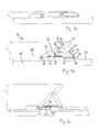
- FIG. 1 Ski equipment generally designated by 10 comprises a climbing aid 12 and a ski pole 14.
- the climbing aid 12 is an element of a rear binding part of a touring ski binding mounted on a ski 16.
- FIG. 1 only a portion of the ski 16 is shown, with an in FIG. 1 right end of the section faces the ski tip, while a in FIG. 1 left end of the section facing the ski end.
- the climbing aid 12 could equally be mounted in the opposite direction on the ski, so that respect FIG. 1 the ski tip is located on the left and the ski end on the right.
- the configuration with ski tip right in FIG. 1 in particular in order to keep torque loads of the lever elements of the climbing aid small at small gradients.
- a first support member 18 has at its upper end a support surface 20 for the heel portion of a ski boot or a ski boot holding support plate, and is on opposite lower end on a parallel to the surface 22 of the ski 16 and perpendicular to the longitudinal axis L of the ski 16 extending pivot axis 24 pivotally mounted.
- the support member 18 is forked formed with an upper plate portion 26 and two lower spaced from each other in parallel from the plate portion 26 extending from webs 28, which are respectively pivotally coupled to end portions of the pivot axis 24 with this.
- the upper plate section 26 could also be completely dispensed with, so that the support surface 20 is arranged in the region of the connection axis 34.
- the first support member 18 and the second support member 30 then form together an inverted V-shaped lever arrangement.
- the webs 32, 32 are connected to each other via a transverse web 36, so that the second support member 30 is formed substantially U-shaped.
- the crossbar 36 is orthogonal to the ski longitudinal direction L and parallel to the ski longitudinal surface 22. With the transverse web 36 and with the lower ends of the webs 32, 32, the second support member 30 is supported on a Counter support section 38 of a ski 16 attached to the plate 40 from.
- connection axis 34, the pivot axis 24 and the counter support section 38 or the transverse web 36 describe a force triangle, via which a compressive force acting on the support surface 20 is stably introduced into the ski 16 by a ski boot or cleat.
- the force triangle By the force triangle the climbing aid is secured against tilting along the ski longitudinal direction L, wherein by the transverse web 36 of the second support member 30 and the spaced webs 28, 28 of the first support member 18, a stable grip against tilting is ensured perpendicular to the ski longitudinal direction L.
- the height of the support surface 20 above the surface 22 of the ski 16 and thus the height h of the climbing aid 12 per se can be changed by changing the distance between the pivot axis 24 and the crossbar 36, more precisely by a movement of the crossbar 36 effect on the skifest positioned pivot axis 24 to or from this away.
- the angle ⁇ between the first support member 18 and the second support member 30 changes, so that the first support member 18 and with this the support surface 20 applies to the ski 16 or stands out from it.
- the height of the climbing aid can be adjusted from a minimum value of approximately 14 mm to a maximum value of approximately 76 mm.
- an inner space of the cylinder 46 is divided into a first hydraulic chamber 52 and a second hydraulic chamber 54.
- the hydraulic chambers 52, 54 are connected to each other via hydraulic lines 56a, 56b, 56c, 56d, 56e, wherein in this connection (in the exemplary embodiment in hydraulic line 56c) a valve 58 is arranged, which can block or connect the hydraulic line 56c in hydraulic communication connection.
- the interior of the cylinder 46 and the hydraulic lines 56a ... 56e is filled with hydraulic fluid.
- hydraulic fluid can flow from one hydraulic chamber into the other hydraulic chamber via the hydraulic lines 56a... 56e and the valve 58 during a movement of the piston 48 in the cylinder 46, so that the piston 48 and thus the crosspiece 36 for adjusting the Height of the climbing aid 12 can move.
- the second hydraulic chamber 54 is further connected via a hydraulic line 56f to a surge tank 60 which receives a variable supply of hydraulic fluid.
- a biased by a spring 61 piston 62 is provided to compensate for the variable volume of the surge tank 60 .
- a coil spring 64 is arranged, which is wound around the piston rod 50, and on the one hand on the piston 48 and on the other hand on the transverse web 36 facing inner end of the cylinder 46 is supported.
- the spring 64 biases the piston 48 in the retraction direction, i. in the direction of a shortening of a distance between the transverse web 36 and axis 24 and thus in the direction of increasing the support surface 20 of the climbing aid 12.
- the spring 64 and the spring 61 are coordinated so that the spring 61 of the surge tank 60 is not the force of the spring 64th overcomes and moves the piston 48 in the extension direction.
- valve 58 could be operated directly.
- the valve 58 is connected as a solenoid valve via a control line 66 to a control electronics 68, which is located in a housing adjacent to the actuator 42.
- the control electronics 68 comprises an in FIG. 2 only schematically indicated wireless receiver 70, which is in wireless communication with a built-in ski pole 14 wireless transmitter 72 to the wireless transmitter 72 to wireless information about a triggering adjustment to receive. Based on the received wireless information, the wireless receiver 70 sets a control signal, which is transmitted via the control line 66 to the valve 58 to switch the valve 58.
- the control electronics 68 also includes the necessary for the operation of the wireless receiver 70 power supply, in particular a battery and associated electronics.
- position sensors 71 can be seen, which are arranged along the displacement path of the piston 48 spaced apart on the cylinder 46.
- the position sensors 71 detect a position of the piston 48 within the cylinder 46 and register at least a passing of the piston 48 on one of the position sensors 71.
- the position sensors 71 transmit a position signal to the control electronics 68.
- the adjusting element 42 has an emergency unlocking device, which comprises a bridging valve 63 and hydraulic lines 56g, 56h, 56i.
- the hydraulic lines 56g, 56h, 56i form a bypass for bypassing the valve 58.
- the bypass valve 63 e.g. by a manually operable switch to open a connection between first and second hydraulic chambers 52, 54.
- the climbing aid 12 can then be manually moved to the desired position.
- An alternative emergency release could be provided in that the first support member 18 or the second support member 30 at one of the three points oflisteddreickecks, ie on the mating support portion 38, on the pivot axis 24, or on the connection axis 34, can be posted so that the climbing aid 12 can be folded at least in the lowest position in case of malfunction of the actuating element, or the electronics 68.
- the already mentioned wireless transmitter 72 is integrated together with a battery 74 for powering the wireless transmitter 72 inside the handle 73, so that it is well protected against cold and moisture.
- the wireless transmitter 72 includes a wireless end circuit 75, a rocker switch 76, and a display 77.
- the rocker switch 76 is disposed on an upper ski-facing portion of the handle 73 so that it is easily accessible and operable by a skier's thumb.
- the rocker switch 76 has an upper switching section 78, with which an increase in the climbing aid 12 is instructed by one step, and has a lower switching section 80, with which a lowering of the climbing aid 12 is instructed by one step.
- the rocker switch 76 is connected to the wireless end circuit 75 to set a corresponding wireless signal in response to an operation of the rocker switch 76.
- the display device 77 includes four light emitting diodes 82 arranged on an upper front portion of the handle 73 in a row on an imaginary continuation line through the lower switching section 80 and the upper switching section 78.
- the LEDs 82 are powered by the battery 74 with energy and operated by an electronic unit, not shown in accordance with the currently set height of the climbing aid 12.
- the four light emitting diodes each indicate one of four stages in which the height of the climbing aid 12 can be changed by respective actuation of the rocker switch 76.
- the valve 58 can be opened either only for a certain time via a timing mechanism or the position of the piston 48 is detected via the position sensors 71, so that as soon as the piston 48 is detected by the next position sensor 71, the control electronics 68, the valve 58 again switches to the blocking state (actuator 42 locked), whereupon the adjusting operation is completed.
- a wireless signal for reducing the height of the climbing aid 12 is lowered by one step and the light-emitting diode display 82 is switched over accordingly.
- the control electronics 68 switches the valve 58 in the open state, so that a displacement of the piston 48 and thus an adjustment of the climbing aid 12 is made possible (actuator 42 dearretiert).
- the displacement of the piston 48 must be done to reduce the height of the climbing aid 12, however, against the action of the spring 64. For this purpose, it is necessary that the skier exerts slight pressure on the support surface 20 or stands with his full weight on the climbing aid 12.
- the control electronics 68 switches the valve 58 back to the blocking state, so that the lowering of the climbing aid 12 is completed by one stage.
- the climbing aid is always pushed down by the force of the skier in the downward direction to the position with minimum height and then after relief of the climbing aid 12, a gradual increase in the climbing aid 12 is possible.
- both wireless receivers 70 and wireless transmitters 72 are designed as wireless transceivers, so that both elements can both transmit and receive wireless signals in order to enable wireless communication also in the direction from the climbing aid to the ski pole. This can be exploited to transmit a successful adjustment of the climbing aid or another operating state of the climbing aid to the wireless end receiver of the ski pole to reliably display the set height of the climbing aid or the operating state of the climbing aid on the display device.
- FIG. 6 shows a grip portion of a ski pole 14 'of equipment according to a second embodiment of the invention.
- the ski pole 14 'of the second embodiment differs from the ski pole 14 of the first embodiment only in construction and operation of the operation switch 76' and the display direction 82 '.
- the actuating switch 76 ' is designed as a rotary switch and comprises an actuating lever 84' which is mounted about an axis 86 'pivotally mounted on the ski pole 14'.
- the operating lever 84 ' may be adjusted by the skier to various angular positions corresponding to respective adjustment stages of the associated climbing aid (not shown).
- the skier can thus quickly adjust the actuating lever 84 'over several stages away in the desired level, and thus immediately instruct the desired change in the height of the climbing aid and run.
- it does not have to actuate the actuating device 76 'several times, as was necessary in the first embodiment by the use of the rocker switch 76.
- the actuating lever 84 ' is connected to a circular segment-shaped display element 88' which extends from the actuating lever 84 'upwards and forwards into the region of a display window 90', so that a section of the display element 88 'in the window 90' to recognize is.
- the display element 88 ' carries the adjustment steps of the climbing aid corresponding markings, so that at the corresponding setting angles of the actuating lever 84' of the set levels corresponding marking of the display element 88 'through the window 90' is displayed. In this way, a simple mechanical display capability is realized and an electronic display can be dispensed with.
- the wireless transmitter 72 'of the second embodiment is adapted to convert a signal corresponding to a certain angular position of the actuating lever 84' into a corresponding wireless signal to cause the climbing aid to adjust the corresponding height.
- the wireless transmitter 72 ' can either settle the necessary number of Einzeldrahtlossignalen to increase or decrease the climbing aid by exactly one level or can settle a signal for adjusting the climbing aid by a certain number of levels or can provide a signal for setting the climbing aid in a predetermined level send.
- the wireless receiver 70 'and the wireless transmitter 72' can each be designed as a wireless transceiver for bidirectional communication between the two elements, so that a set level of climbing or other operating condition can be suitably signaled to the skier.
- the wireless transmitter 72; 72 'be provided as a retrofit element, with which a conventional ski pole with wireless end functionality according to the invention retrofitted to actuate a wireless communication adjustable ski binding of the invention.
- the retrofittable wireless transmitter could include a suitable universal retention means for temporary or permanent mounting to the handle portion of a ski pole.
- the wireless transmitter which may also function as a receiver, could however also be accommodated on the skier's clothing or other equipment, such as e.g. in the chest area on the carrying strap of a backpack or on the ski or on the ski binding in front of the ski binding for operation by means of the ski pole tip.
- the wireless communication was realized by radio communication.
- the wireless transmitter 72; 72 'and the wireless receiver 70; 70 ' were therefore set up to transmit and receive radio signals.
- infrared signals or ultrasonic signals could be exchanged between transmitter and receiver.
- FIGS. 7a to 7c With reference to FIGS. 7a to 7c will be explained below a climbing aid according to a third embodiment of the invention.
- the climbing aid of the third exemplary embodiment differs in principle from the climbing aid of the first exemplary embodiment in the use of an electrically operated threaded spindle arrangement 42 "as an adjusting element instead of the hydraulic piston-cylinder arrangement of the first exemplary embodiment as output member a threaded spindle 50 "rotatably drives.
- Electric motor 46 "and threaded spindle 50" extend parallel to the ski longitudinal axis L. The electric motor 46 "is attached to the ski 16.
- a nut 51 (eg a ball nut).
- the nut 51 is received between the webs 32 of the second support member 30 and pivotally connected to the lower ends of the webs 32 on an axle 53.
- the threaded spindle assembly 42 with its elements electric motor 46
- threaded spindle 50 "and nut 51” forms a counter support section fixed to the ski 16, on which the second support member 30 with the axis 53 "is supported.
- the electric motor 46 communicates with control electronics 68" which inter alia include a wireless receiver (not shown) for receiving wireless signals from an associated wireless transmitter (not shown, for example, integrated in the ski pole) and sending appropriate control signals to the electric motor 46 ".
- Control electronics 68 "and electric motor 46" are powered by a battery 92 "with energy.
- a change in a height h of the support surface over the surface of the ski 16 takes place after receiving a corresponding wireless signal by controlling the electric motor 46 ", which puts the threaded spindle 50" in rotation. Accordingly, the nut 51 "of the second support member 30 moves in a linear direction along the ski longitudinal axis L on the electric motor 46" to or from this away, so that applies the climbing aid or sets up.
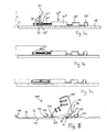
- FIG. 8 shows a fourth embodiment of the invention in a schematic cross-sectional view.
- a touring ski binding generally designated 100, includes a front binding member 102 and a rear binding member 104 fixedly mounted on a ski 16.
- the front binding part has a pivot bearing 106 on which a toe section 108 of a ski boot 110 is held so that the ski boot 110 can pivot about a pivot axis formed by the pivot bearing 106, perpendicular to the longitudinal direction L and parallel to the surface 22 of the ski 16 extending pivot axis.
- the rear binding part comprises a climbing aid 12, for example a climbing aid according to one of the exemplary embodiments explained above, as well as a heel mount 112.
- the heel mount 112 is in the longitudinal direction L of the ski displaceable in order to engage in a known manner a heel-side projection 114 of the ski boot 110 to hold the ski boot 110 in the event of a downhill in the heel section of the ski.
- the heel holder 112 is moved backwards and releases the heel projection 114 free.
- the ski boot 110 can then lift upwards and is supported in the downward direction on the support surface 20 of the climbing aid 12.
- the height of the climbing aid 12 is adjustable by means of an adjusting element (for example with the piston-cylinder arrangement 42 of the first exemplary embodiment or the threaded spindle arrangement 42 of the second exemplary embodiment.)
- the ski binding 110 comprises of the fourth embodiment, an actuating button 116, which is provided on the front binding portion 102. More specifically, the actuating button 116 is located between the pivot bearing 106 and a ski tip 118. The actuating button 116 is therefore easy to reach for the skier and can, for example by means of a ski pole, If a display device is located at a comparable location, then this is also clearly visible to the skier.
- actuation button 116 and the adjusting element of the climbing aid 12 is an in FIG. 8 not shown connection to transmit an operating instruction from the actuating button 116 to the actuator.
- Actuation of the actuation button 116 may also affect other binding or binding adjustment, eg, movement of the rear heel holder 112.
- a signal transmitted by a wireless transmitter eg, the wireless dock integrated in the first and second embodiments
- the pivot axis 24 of the first support member 18 could coincide with the pivot axis of the pivot bracket 106, so that the first support member 18 in the manner of a pivoting cleat supports the ski boot 110 substantially over its entire sole length.
- the ski boot 110 could then also be fixedly mounted on the first support element 18, held.
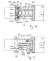
- FIGS. 9 and 10 show a fifth embodiment of the present invention, which is a further modification of the first embodiment, so that in the following only the elements and functions deviating from the first embodiment will be described and otherwise expressly to the detailed description of the first embodiment with reference to FIGS. 1 to 5 is referenced. Also in FIGS. 9 and 10 For example, an upper half of a housing 202 is cut off for illustrative purposes, so that the interior of a locking mechanism 204 is visible.
- the locking mechanism 204 comprises a locking rod 206, which is coupled at one end to the transverse web 36 of the second support member 30 and slidably inserted with the other end in a cylindrical guide 208.
- the cylindrical guide 208 is formed in the housing 202 so that an upper half of the cylindrical guide 208 in FIG FIGS. 9 and 10 not shown.
- the locking rod 206 can move in the longitudinal direction L to move the crosspiece 36 of the second support member 30 to the axis 24 of the first support member 18 to or away.
- the locking rod 206 has a spring stop 210, in the exemplary embodiment a orthogonal to the ski longitudinal axis L extending strut. Between the spring stop 210 and the housing 202 acts at least one spring 212 to bias the locking rod 206 in the retraction in the cylindrical guide 208, so that the climbing aid sets up.
- two springs 212 are held on both sides of the cylindrical guide 208 in pot-like spring guides 214, so that they are supported on the floor 216 of the spring guides 214 on the one hand and on the spring stop 210 on the other hand and held in the compressed state.
- the locking rod 206 has a plurality of locking grooves 218, which are arranged with respect to the ski longitudinal axis L at intervals from each other.
- the latching grooves 218 are designed as annular grooves. In the locking grooves engages a locking projection 220, which is part of an actuating element 221.
- the adjusting element 221 is adjustable between a locking position in which the locking projection 220 is engaged with one of the locking grooves 218 and thus a displacement of the locking rod 206 is blocked in the cylindrical guide 208 (change in the height of the climbing aid blocked), and a dearretierposition, in which retracts the locking projection 220 and is not engaged with any of the locking grooves 218 so that the locking bar 206 can move in the cylindrical guide 208 (change in the height of the climbing aid released).
- the actuator 221 includes a piston 222 and a cylinder 224, in which the piston 222 is slidably inserted.
- the locking projection 220 is formed and protrudes from the cylinder 224.
- a spring 226 acting between the cylinder 224 and the piston 222 biases the piston 222 toward the locking rod 206, so that the locking projection 220 is pressed into the engagement position with a latching groove 218.
- an electromagnet 228 is arranged, which upon excitation the piston 222 attracts and retracts against the force of the spring 226 from the latching engagement. As long as the solenoid 228 is energized, the detent projection 220 is held in the retracted position and the actuator 221 remains in the dearlock position.
- the locking projection 220 is pressed by the force of the spring 226 in the direction of the locking rod 206 and passes or remains in engagement with a arranged at the same position locking groove 218 of the locking rod 206.
- the solenoid 228 is connected via a control line 230 of the control electronics 68 supplied, so that the control electronics 68, the control element 221, eg switch between the lock position and the dearretier position based on a wireless signal received from a wireless receiver 70.
- the skier actuates the adjusting element 221 by a suitable actuating means, in particular by wireless operation of the ski pole 14 via the wireless receiver 70 and the control electronics 68, so that the control 221 switches to the dearretierposition.
- the movement of the locking rod 206 in the cylindrical guide 208 is now released, so that the height of the climbing aid is variable.
- An upward movement of the climbing aid can be done by reducing the pressure force by the skier on the climbing aid, so that the springs 212 can move the locking rod 206 in the retraction and erects the climbing aid.
- a reduction in the height of the climbing aid can be done by increasing the pressure of the skier on the climbing aid, so that the force of the springs 212 is overcome and the climbing aid is depressed.
- the actuator 221 is switched from the Dearretierposition in the locking position (de-energizing the electromagnet 228), so that the locking projection 220 is pressed to the locking rod 206 back. If the locking projection 220 just hits a latching groove 218, the climbing aid becomes instantaneous locked and another height adjustment is blocked.
- the latching piston 206 will either move in the retraction direction or in the extension direction depending on the pressure force of the skier, the latching projection 220 sliding on the latching piston 206 until a next latching groove 218 the latching projection 220 is opposite and the latching projection 220 engages in the latching groove 218. The adjustment of the climbing aid is then completed.
- the fifth embodiment may include a position detecting means which detects the position of the detent rod 206 in the cylindrical guide 208 or which detects in which of the detent grooves 218 of the detent projection 220 is engaged to on the basis of this detection result, the setting level of the climbing aid to the skier signal.
- a Dearretiermechanismus 304 of the sixth embodiment two actuators 321 a, 312b, which are each independently controllable by respective control lines 330a, 330b of the control electronics 68.
- the adjusting elements 321 a and 321 b are each equipped with a piston 322a or 322b biased in the direction of a locking bar 306, which each have a latching projection 320a or 320b.
- the latching projections 320a, 320b of the sixth embodiment have one-sided run-off slopes 323a, 323b, which respectively allow the displacement of the latching rod in one direction displacing the piston 322a or 322b, while blocking a displacement of the latching rod 306 in the opposite direction.
- the drainage slopes 322a, 322b of the two control elements 321 a, 321 b are directed opposite to each other, so that when both control elements 321 a, 321 b in the engaged position (in the direction of the locking rod 306 shifted, electromagnets 328 a, 328 b off) of the locking bar 306 is blocked in both directions.
- the skier actuates an actuating switch in the sense of a downward movement of the climbing aid (for example a downwards switch on the ski pole) to lower the climbing aid by one latching position.
- the control electronics 68 energize the electromagnet 328a of the first actuator 321a while the electromagnet 328b of the second actuator 321b remains de-energized.
- the second actuator 321 b prevents movement of the locking rod 306 in the sense of an outward movement of the climbing aid. If the skier applies sufficient pressure to the climbing aid, i. a pressure exceeding the force of the springs 312, so the locking bar 306 slips over the drainage slope 323b of the second control element 321 b, so that the height of the climbing aid is reduced. This movement continues until the electromagnet 328a of the first actuator 321a is de-energized, e.g. upon reaching the desired next detent step, so that then an adjustment of the climbing aid is blocked again in both directions.
- the locking projection with a corresponding Groove a locking rod can engage.
- a catch is also envisaged, which is pivotally mounted in the vicinity of the locking rod, so that a locking tooth of the latch can pivot into engagement and out of engagement with a locking groove of the locking rod.
- the pivoting movement of the latch can be controlled by an electromagnet, which in this case the additional advantage that can be created by the pivotal mounting of the latch a lever assembly with different lengths levers, of which a longer lever provides the locking tooth and a shorter lever from the electromagnet is tightened or released, so that a relatively high travel of the locking tooth between the engaged position and disengaged position is possible with only small Anteuerungsweg of attracted by the electromagnet or released second lever.
- FIG. 12 shows a climbing aid according to a seventh embodiment of the invention.
- the seventh embodiment is a modification of the first embodiment which has been described above in detail with reference to FIG FIG. 2 have been described.
- FIG. 12 are the same or corresponding elements as designated in the first embodiment with reference numerals increased by 400 and their re-description is omitted. It is expressly made in this regard to the detailed description of the first embodiment.
- the already mentioned in the sixth embodiment effect is achieved that an adjustment for the climbing aid can be specified by the skier, with an unintentional adjustment is prevented in the non-directed direction.
- the first hydraulic chamber 452 and the second hydraulic chamber 454 by two hydraulic branches 457a and 457b connected in parallel with each other connected.
- the first hydraulic branch 457a has a series connection of a one-way valve 459a and a switchable valve 458a.
- the second hydraulic branch 457b has a series connection of a one-way valve 459b and a switching valve 458b.
- the one-way valve 459a of the first hydraulic branch 457a is directed to allow fluid flow from the second hydraulic chamber 454 to the first hydraulic chamber 452 but to block fluid flow in the opposite direction.
- the one-way valve 459b of the second hydraulic branch 457b is opposite to the first one-way valve 459a, ie, it allows fluid flow from the first hydraulic chamber 452 to the second hydraulic chamber 454 and blocks an opposing fluid flow.
- the switching valve 458a of the first hydraulic branch 457a is closed by appropriate signals of the control electronics 68 and the switching valve 458b of the second hydraulic branch 457b is opened. Hydraulic fluid may then flow between the first hydraulic chamber 452 and the second hydraulic chamber 454 only via the second hydraulic branch 457b which, due to the one-way valve 459b, allows only flow from the first hydraulic chamber 452 into the second hydraulic chamber 454 but blocks reverse flow. Accordingly, in this switch position, the piston 448 can only be moved in the extension direction, i. The climbing aid can only be pushed downwards and will not move upwards in an undesired manner when it is relieved.
- the switching valve 458a of the first hydraulic branch 457a is opened, and the switching valve 458b of the second hydraulic branch 457b is closed so that hydraulic fluid from only the second hydraulic chamber 454 into the first hydraulic chamber due to the one-way valve 459a 452 can flow and thus the piston 448 is displaceable only in the retraction direction.
- the climbing aid can then be moved upwards with relief, but even under heavy load
- both switching valve 458a, 458b are closed so that any replacement of hydraulic fluid between the two hydraulic chambers 452 and 454 is prevented and the set height of the climbing aid is locked for the normal use of the climbing aid.
- the locking rod 206 of the fifth embodiment may be formed by a piston rod of a piston-cylinder assembly on the model of the first embodiment, so that such a variant comprises a total of two control elements, one for changing the height of the climbing aid and a second for locking or Dearret mich the height adjustment.
- connection between the two hydraulic chambers produced by extending outside of the hydraulic cylinder hydraulic lines or hydraulic branches.
- a connecting line between the chambers of a piston-cylinder arrangement can alternatively also be arranged within the piston separating the chambers from one another, in which case also the valve for releasing or blocking the connecting line within the piston Piston is arranged.
- a gas spring an arrangement of this kind is known per se, for example for gas spring elements of height-adjustable chairs in the prior art and could be advantageously used in a climbing aid according to the invention due to its particularly compact design.
Landscapes
- Footwear And Its Accessory, Manufacturing Method And Apparatuses (AREA)
- Fittings On The Vehicle Exterior For Carrying Loads, And Devices For Holding Or Mounting Articles (AREA)
Applications Claiming Priority (1)
| Application Number | Priority Date | Filing Date | Title |
|---|---|---|---|
| DE102009036244A DE102009036244A1 (de) | 2009-08-05 | 2009-08-05 | Steighilfe, Tourenskibindung und Skiausrüstung |
Publications (4)
| Publication Number | Publication Date |
|---|---|
| EP2281615A2 true EP2281615A2 (fr) | 2011-02-09 |
| EP2281615A3 EP2281615A3 (fr) | 2012-12-26 |
| EP2281615B1 EP2281615B1 (fr) | 2016-03-02 |
| EP2281615B2 EP2281615B2 (fr) | 2019-01-23 |
Family
ID=43126978
Family Applications (1)
| Application Number | Title | Priority Date | Filing Date |
|---|---|---|---|
| EP10172077.9A Active EP2281615B2 (fr) | 2009-08-05 | 2010-08-05 | Aide à la montée, fixation de ski de fond et équipement de ski |
Country Status (2)
| Country | Link |
|---|---|
| EP (1) | EP2281615B2 (fr) |
| DE (1) | DE102009036244A1 (fr) |
Cited By (7)
| Publication number | Priority date | Publication date | Assignee | Title |
|---|---|---|---|---|
| WO2014135693A1 (fr) * | 2013-03-08 | 2014-09-12 | Micado Cad-Solutions Gmbh | Talonnière pour fixation de ski de randonnée |
| WO2016144187A1 (fr) * | 2015-03-12 | 2016-09-15 | Rottefella As | Système de positionnement dynamique facultatif de fixation de ski |
| WO2017095232A1 (fr) * | 2015-11-30 | 2017-06-08 | Rottefella As | Système pour positionnement dynamique facultatif d'une fixation de ski sur un ski |
| AT524097A1 (de) * | 2020-07-17 | 2022-02-15 | Christoph Beisteiner | Steighilfe für eine Tourenschibindung |
| WO2022089731A1 (fr) * | 2020-10-27 | 2022-05-05 | Edelsbrunner Martin | Élément talon pour fixation de ski de fond |
| AT525738B1 (de) * | 2022-03-17 | 2023-07-15 | Heinrich Muenster Dipl Ing | Motorische Schreit- bzw. Steighilfe |
| AT526681A4 (de) * | 2023-02-13 | 2024-06-15 | Robert Gahr | Steighilfe für eine Skibindung |
Families Citing this family (1)
| Publication number | Priority date | Publication date | Assignee | Title |
|---|---|---|---|---|
| PL233384B1 (pl) | 2017-06-22 | 2019-10-31 | Backwards Spolka Z Ograniczona Odpowiedzialnoscia | Wiązanie, adapter i sposób mocowania butów oraz but do nart lub deski splitboardowej lub nartorolek lub rakiet śnieżnych |
Citations (2)
| Publication number | Priority date | Publication date | Assignee | Title |
|---|---|---|---|---|
| EP0724899A2 (fr) | 1995-02-06 | 1996-08-07 | Fritschi Ag, Apparatebau | Fixation de ski |
| WO2007079604A1 (fr) | 2006-01-11 | 2007-07-19 | Fritschi Ag - Swiss Bindings | Dispositif d'aide à la montée |
Family Cites Families (11)
| Publication number | Priority date | Publication date | Assignee | Title |
|---|---|---|---|---|
| US4002354A (en) † | 1975-02-26 | 1977-01-11 | Ramer Paul C | Ski binding |
| DE3309295A1 (de) * | 1983-03-16 | 1984-09-20 | Hans-Dieter 7121 Gemmrigheim Layh | Brems- und geschwindigkeitssteuereinrichtung fuer ski |
| US4672766A (en) † | 1984-05-04 | 1987-06-16 | Mattison Robert N | Fishing jig and method of making same |
| US4674766A (en) | 1985-02-21 | 1987-06-23 | Alpine Research, Inc. | Alpine-touring ski binding |
| DE3702149A1 (de) † | 1987-01-24 | 1988-08-04 | Vaude Sport Albrecht Von Dewit | Skibindung fuer touren- und abfahrtslauf |
| DE19915844A1 (de) † | 1999-04-08 | 2000-10-19 | Christian Verlohr | Aufsteighilfe zum Laufen, Ansteigen und evtl. auch zum Abfahren auf schneebedecktem Untergrund |
| US7104564B2 (en) * | 2000-08-10 | 2006-09-12 | Martin Ralph M | Backwards release ski binding |
| WO2004035153A2 (fr) † | 2002-10-17 | 2004-04-29 | Pupko Michael M | Fixation de ski reglable en vue d'ameliorer l'equilibre |
| WO2008083511A1 (fr) † | 2007-01-11 | 2008-07-17 | Fritschi Ag - Swiss Bindings | Dispositif servant de cale de montée |
| DE102008050044B4 (de) * | 2008-10-01 | 2017-05-11 | Marker Deutschland Gmbh | Skibindung |
| DE102011015785A1 (de) * | 2011-04-01 | 2012-10-04 | Reinhold Zoor | Fernbedienung für Steighilfe |
-
2009
- 2009-08-05 DE DE102009036244A patent/DE102009036244A1/de not_active Ceased
-
2010
- 2010-08-05 EP EP10172077.9A patent/EP2281615B2/fr active Active
Patent Citations (2)
| Publication number | Priority date | Publication date | Assignee | Title |
|---|---|---|---|---|
| EP0724899A2 (fr) | 1995-02-06 | 1996-08-07 | Fritschi Ag, Apparatebau | Fixation de ski |
| WO2007079604A1 (fr) | 2006-01-11 | 2007-07-19 | Fritschi Ag - Swiss Bindings | Dispositif d'aide à la montée |
Cited By (11)
| Publication number | Priority date | Publication date | Assignee | Title |
|---|---|---|---|---|
| WO2014135693A1 (fr) * | 2013-03-08 | 2014-09-12 | Micado Cad-Solutions Gmbh | Talonnière pour fixation de ski de randonnée |
| WO2016144187A1 (fr) * | 2015-03-12 | 2016-09-15 | Rottefella As | Système de positionnement dynamique facultatif de fixation de ski |
| US10322331B2 (en) | 2015-03-12 | 2019-06-18 | Rottefella As | System for optional dynamic positioning a ski binding |
| EA034724B1 (ru) * | 2015-03-12 | 2020-03-12 | Роттефелла Ас | Система для опционного динамического позиционирования лыжного крепления |
| WO2017095232A1 (fr) * | 2015-11-30 | 2017-06-08 | Rottefella As | Système pour positionnement dynamique facultatif d'une fixation de ski sur un ski |
| AT524097A1 (de) * | 2020-07-17 | 2022-02-15 | Christoph Beisteiner | Steighilfe für eine Tourenschibindung |
| WO2022089731A1 (fr) * | 2020-10-27 | 2022-05-05 | Edelsbrunner Martin | Élément talon pour fixation de ski de fond |
| AT525738B1 (de) * | 2022-03-17 | 2023-07-15 | Heinrich Muenster Dipl Ing | Motorische Schreit- bzw. Steighilfe |
| AT525738A4 (de) * | 2022-03-17 | 2023-07-15 | Heinrich Muenster Dipl Ing | Motorische Schreit- bzw. Steighilfe |
| AT526681A4 (de) * | 2023-02-13 | 2024-06-15 | Robert Gahr | Steighilfe für eine Skibindung |
| AT526681B1 (de) * | 2023-02-13 | 2024-06-15 | Robert Gahr | Steighilfe für eine Skibindung |
Also Published As
| Publication number | Publication date |
|---|---|
| EP2281615B2 (fr) | 2019-01-23 |
| EP2281615A3 (fr) | 2012-12-26 |
| EP2281615B1 (fr) | 2016-03-02 |
| DE102009036244A1 (de) | 2011-02-17 |
Similar Documents
| Publication | Publication Date | Title |
|---|---|---|
| EP2281615B1 (fr) | Aide à la montée, fixation de ski de fond et équipement de ski | |
| EP2659939B1 (fr) | Unité de talon pour une fixation de ski de randonnée | |
| EP0754079B1 (fr) | Fixation de ski | |
| EP3766550B1 (fr) | Dispositif automatique avant | |
| EP2608853B1 (fr) | Butée arrière de randonnee avec plage de glissement dynamique | |
| EP2351603B1 (fr) | Fixation de ski dotée d'une aide à la montée | |
| EP3498345B1 (fr) | Fixation de ski légère à sécurité de déclenchement augmentée | |
| EP2762209B1 (fr) | Talonnière avec levier auxiliaire | |
| EP2281616B1 (fr) | Equipement de planche de glisse et fixation à telecommande sans fil pour une planche de glisse | |
| EP3566754B1 (fr) | Butée avant de fixation de ski | |
| EP2570160B1 (fr) | Unité de talon pour une fixation de ski de randonée | |
| EP2666525B1 (fr) | Talonnière avec cale de montée et ensemble stop-ski | |
| EP2172251B1 (fr) | organe d'actionnement pour fixation de ski | |
| DE102012201812B4 (de) | Vordereinheit für eine Gleitbrettbindung, Tourenbindung und Skisprungbindung | |
| EP2898931A1 (fr) | Fixation de ski dotée de module de fixation d'avant-pied | |
| EP2813268A1 (fr) | Automate avant | |
| EP3195906B1 (fr) | Talonniere ayant une configuration de marche | |
| DE102012206880A1 (de) | Vordereinheit für eine Gleitbrettbindung, insbesondere schwenkbare Vordereinheit mit Auslöseanordnung | |
| CH706664A1 (de) | Skibindung. | |
| EP2826528B1 (fr) | Unité avant d'une fixation de planche de glisse | |
| DE2617395A1 (de) | Vorrichtung fuer eine in skilaengsrichtung verstellbare bindung | |
| DE2707780A1 (de) | Hintere skibindung mit einer haltevorrichtung, die mit geeigneten elastischen mitteln waehrend der beanspruchung des ski gleiten kann | |
| EP3103525B1 (fr) | Talonnière | |
| AT368700B (de) | Skibremse an einer ausloeseskibindung | |
| AT401232B (de) | Bremsvorrichtung für eine gleiteinrichtung, insbesondere für einen schi oder ein snowboard |
Legal Events
| Date | Code | Title | Description |
|---|---|---|---|
| PUAI | Public reference made under article 153(3) epc to a published international application that has entered the european phase |
Free format text: ORIGINAL CODE: 0009012 |
|
| AK | Designated contracting states |
Kind code of ref document: A2 Designated state(s): AL AT BE BG CH CY CZ DE DK EE ES FI FR GB GR HR HU IE IS IT LI LT LU LV MC MK MT NL NO PL PT RO SE SI SK SM TR |
|
| AX | Request for extension of the european patent |
Extension state: BA ME RS |
|
| PUAL | Search report despatched |
Free format text: ORIGINAL CODE: 0009013 |
|
| AK | Designated contracting states |
Kind code of ref document: A3 Designated state(s): AL AT BE BG CH CY CZ DE DK EE ES FI FR GB GR HR HU IE IS IT LI LT LU LV MC MK MT NL NO PL PT RO SE SI SK SM TR |
|
| AX | Request for extension of the european patent |
Extension state: BA ME RS |
|
| RIC1 | Information provided on ipc code assigned before grant |
Ipc: A63C 9/08 20060101AFI20121121BHEP |
|
| 17P | Request for examination filed |
Effective date: 20130625 |
|
| RBV | Designated contracting states (corrected) |
Designated state(s): AL AT BE BG CH CY CZ DE DK EE ES FI FR GB GR HR HU IE IS IT LI LT LU LV MC MK MT NL NO PL PT RO SE SI SK SM TR |
|
| 17Q | First examination report despatched |
Effective date: 20140103 |
|
| GRAP | Despatch of communication of intention to grant a patent |
Free format text: ORIGINAL CODE: EPIDOSNIGR1 |
|
| INTG | Intention to grant announced |
Effective date: 20150507 |
|
| GRAS | Grant fee paid |
Free format text: ORIGINAL CODE: EPIDOSNIGR3 |
|
| GRAA | (expected) grant |
Free format text: ORIGINAL CODE: 0009210 |
|
| AK | Designated contracting states |
Kind code of ref document: B1 Designated state(s): AL AT BE BG CH CY CZ DE DK EE ES FI FR GB GR HR HU IE IS IT LI LT LU LV MC MK MT NL NO PL PT RO SE SI SK SM TR |
|
| REG | Reference to a national code |
Ref country code: GB Ref legal event code: FG4D Free format text: NOT ENGLISH |
|
| REG | Reference to a national code |
Ref country code: AT Ref legal event code: REF Ref document number: 777591 Country of ref document: AT Kind code of ref document: T Effective date: 20160315 Ref country code: CH Ref legal event code: EP |
|
| REG | Reference to a national code |
Ref country code: IE Ref legal event code: FG4D Free format text: LANGUAGE OF EP DOCUMENT: GERMAN |
|
| REG | Reference to a national code |
Ref country code: DE Ref legal event code: R096 Ref document number: 502010011113 Country of ref document: DE |
|
| REG | Reference to a national code |
Ref country code: NL Ref legal event code: MP Effective date: 20160302 |
|
| REG | Reference to a national code |
Ref country code: LT Ref legal event code: MG4D |
|
| PG25 | Lapsed in a contracting state [announced via postgrant information from national office to epo] |
Ref country code: GR Free format text: LAPSE BECAUSE OF FAILURE TO SUBMIT A TRANSLATION OF THE DESCRIPTION OR TO PAY THE FEE WITHIN THE PRESCRIBED TIME-LIMIT Effective date: 20160603 Ref country code: NO Free format text: LAPSE BECAUSE OF FAILURE TO SUBMIT A TRANSLATION OF THE DESCRIPTION OR TO PAY THE FEE WITHIN THE PRESCRIBED TIME-LIMIT Effective date: 20160602 Ref country code: HR Free format text: LAPSE BECAUSE OF FAILURE TO SUBMIT A TRANSLATION OF THE DESCRIPTION OR TO PAY THE FEE WITHIN THE PRESCRIBED TIME-LIMIT Effective date: 20160302 Ref country code: FI Free format text: LAPSE BECAUSE OF FAILURE TO SUBMIT A TRANSLATION OF THE DESCRIPTION OR TO PAY THE FEE WITHIN THE PRESCRIBED TIME-LIMIT Effective date: 20160302 Ref country code: ES Free format text: LAPSE BECAUSE OF FAILURE TO SUBMIT A TRANSLATION OF THE DESCRIPTION OR TO PAY THE FEE WITHIN THE PRESCRIBED TIME-LIMIT Effective date: 20160302 |
|
| PG25 | Lapsed in a contracting state [announced via postgrant information from national office to epo] |
Ref country code: LV Free format text: LAPSE BECAUSE OF FAILURE TO SUBMIT A TRANSLATION OF THE DESCRIPTION OR TO PAY THE FEE WITHIN THE PRESCRIBED TIME-LIMIT Effective date: 20160302 Ref country code: NL Free format text: LAPSE BECAUSE OF FAILURE TO SUBMIT A TRANSLATION OF THE DESCRIPTION OR TO PAY THE FEE WITHIN THE PRESCRIBED TIME-LIMIT Effective date: 20160302 Ref country code: PL Free format text: LAPSE BECAUSE OF FAILURE TO SUBMIT A TRANSLATION OF THE DESCRIPTION OR TO PAY THE FEE WITHIN THE PRESCRIBED TIME-LIMIT Effective date: 20160302 Ref country code: SE Free format text: LAPSE BECAUSE OF FAILURE TO SUBMIT A TRANSLATION OF THE DESCRIPTION OR TO PAY THE FEE WITHIN THE PRESCRIBED TIME-LIMIT Effective date: 20160302 Ref country code: LT Free format text: LAPSE BECAUSE OF FAILURE TO SUBMIT A TRANSLATION OF THE DESCRIPTION OR TO PAY THE FEE WITHIN THE PRESCRIBED TIME-LIMIT Effective date: 20160302 |
|
| PG25 | Lapsed in a contracting state [announced via postgrant information from national office to epo] |
Ref country code: IS Free format text: LAPSE BECAUSE OF FAILURE TO SUBMIT A TRANSLATION OF THE DESCRIPTION OR TO PAY THE FEE WITHIN THE PRESCRIBED TIME-LIMIT Effective date: 20160702 Ref country code: EE Free format text: LAPSE BECAUSE OF FAILURE TO SUBMIT A TRANSLATION OF THE DESCRIPTION OR TO PAY THE FEE WITHIN THE PRESCRIBED TIME-LIMIT Effective date: 20160302 |
|
| PG25 | Lapsed in a contracting state [announced via postgrant information from national office to epo] |
Ref country code: RO Free format text: LAPSE BECAUSE OF FAILURE TO SUBMIT A TRANSLATION OF THE DESCRIPTION OR TO PAY THE FEE WITHIN THE PRESCRIBED TIME-LIMIT Effective date: 20160302 Ref country code: SM Free format text: LAPSE BECAUSE OF FAILURE TO SUBMIT A TRANSLATION OF THE DESCRIPTION OR TO PAY THE FEE WITHIN THE PRESCRIBED TIME-LIMIT Effective date: 20160302 Ref country code: PT Free format text: LAPSE BECAUSE OF FAILURE TO SUBMIT A TRANSLATION OF THE DESCRIPTION OR TO PAY THE FEE WITHIN THE PRESCRIBED TIME-LIMIT Effective date: 20160704 Ref country code: CZ Free format text: LAPSE BECAUSE OF FAILURE TO SUBMIT A TRANSLATION OF THE DESCRIPTION OR TO PAY THE FEE WITHIN THE PRESCRIBED TIME-LIMIT Effective date: 20160302 Ref country code: SK Free format text: LAPSE BECAUSE OF FAILURE TO SUBMIT A TRANSLATION OF THE DESCRIPTION OR TO PAY THE FEE WITHIN THE PRESCRIBED TIME-LIMIT Effective date: 20160302 |
|
| REG | Reference to a national code |
Ref country code: DE Ref legal event code: R026 Ref document number: 502010011113 Country of ref document: DE |
|
| PLBI | Opposition filed |
Free format text: ORIGINAL CODE: 0009260 |
|
| PG25 | Lapsed in a contracting state [announced via postgrant information from national office to epo] |
Ref country code: BE Free format text: LAPSE BECAUSE OF NON-PAYMENT OF DUE FEES Effective date: 20160831 Ref country code: IT Free format text: LAPSE BECAUSE OF FAILURE TO SUBMIT A TRANSLATION OF THE DESCRIPTION OR TO PAY THE FEE WITHIN THE PRESCRIBED TIME-LIMIT Effective date: 20160302 |
|
| PLAX | Notice of opposition and request to file observation + time limit sent |
Free format text: ORIGINAL CODE: EPIDOSNOBS2 |
|
| 26 | Opposition filed |
Opponent name: MICADO SMART ENGINEERING GMBH Effective date: 20161130 |
|
| PG25 | Lapsed in a contracting state [announced via postgrant information from national office to epo] |
Ref country code: DK Free format text: LAPSE BECAUSE OF FAILURE TO SUBMIT A TRANSLATION OF THE DESCRIPTION OR TO PAY THE FEE WITHIN THE PRESCRIBED TIME-LIMIT Effective date: 20160302 |
|
| PG25 | Lapsed in a contracting state [announced via postgrant information from national office to epo] |
Ref country code: BG Free format text: LAPSE BECAUSE OF FAILURE TO SUBMIT A TRANSLATION OF THE DESCRIPTION OR TO PAY THE FEE WITHIN THE PRESCRIBED TIME-LIMIT Effective date: 20160602 Ref country code: SI Free format text: LAPSE BECAUSE OF FAILURE TO SUBMIT A TRANSLATION OF THE DESCRIPTION OR TO PAY THE FEE WITHIN THE PRESCRIBED TIME-LIMIT Effective date: 20160302 |
|
| PG25 | Lapsed in a contracting state [announced via postgrant information from national office to epo] |
Ref country code: MC Free format text: LAPSE BECAUSE OF FAILURE TO SUBMIT A TRANSLATION OF THE DESCRIPTION OR TO PAY THE FEE WITHIN THE PRESCRIBED TIME-LIMIT Effective date: 20160302 |
|
| REG | Reference to a national code |
Ref country code: CH Ref legal event code: PL |
|
| GBPC | Gb: european patent ceased through non-payment of renewal fee |
Effective date: 20160805 |
|
| PG25 | Lapsed in a contracting state [announced via postgrant information from national office to epo] |
Ref country code: LI Free format text: LAPSE BECAUSE OF NON-PAYMENT OF DUE FEES Effective date: 20160831 Ref country code: CH Free format text: LAPSE BECAUSE OF NON-PAYMENT OF DUE FEES Effective date: 20160831 |
|
| PLBB | Reply of patent proprietor to notice(s) of opposition received |
Free format text: ORIGINAL CODE: EPIDOSNOBS3 |
|
| REG | Reference to a national code |
Ref country code: FR Ref legal event code: ST Effective date: 20170428 |
|
| REG | Reference to a national code |
Ref country code: IE Ref legal event code: MM4A |
|
| PG25 | Lapsed in a contracting state [announced via postgrant information from national office to epo] |
Ref country code: IE Free format text: LAPSE BECAUSE OF NON-PAYMENT OF DUE FEES Effective date: 20160805 Ref country code: GB Free format text: LAPSE BECAUSE OF NON-PAYMENT OF DUE FEES Effective date: 20160805 Ref country code: FR Free format text: LAPSE BECAUSE OF NON-PAYMENT OF DUE FEES Effective date: 20160831 |
|
| PG25 | Lapsed in a contracting state [announced via postgrant information from national office to epo] |
Ref country code: LU Free format text: LAPSE BECAUSE OF NON-PAYMENT OF DUE FEES Effective date: 20160805 |
|
| REG | Reference to a national code |
Ref country code: AT Ref legal event code: MM01 Ref document number: 777591 Country of ref document: AT Kind code of ref document: T Effective date: 20160805 |
|
| PG25 | Lapsed in a contracting state [announced via postgrant information from national office to epo] |
Ref country code: AT Free format text: LAPSE BECAUSE OF NON-PAYMENT OF DUE FEES Effective date: 20160805 |
|
| PG25 | Lapsed in a contracting state [announced via postgrant information from national office to epo] |
Ref country code: HU Free format text: LAPSE BECAUSE OF FAILURE TO SUBMIT A TRANSLATION OF THE DESCRIPTION OR TO PAY THE FEE WITHIN THE PRESCRIBED TIME-LIMIT; INVALID AB INITIO Effective date: 20100805 Ref country code: CY Free format text: LAPSE BECAUSE OF FAILURE TO SUBMIT A TRANSLATION OF THE DESCRIPTION OR TO PAY THE FEE WITHIN THE PRESCRIBED TIME-LIMIT Effective date: 20160302 |
|
| PG25 | Lapsed in a contracting state [announced via postgrant information from national office to epo] |
Ref country code: MK Free format text: LAPSE BECAUSE OF FAILURE TO SUBMIT A TRANSLATION OF THE DESCRIPTION OR TO PAY THE FEE WITHIN THE PRESCRIBED TIME-LIMIT Effective date: 20160302 Ref country code: TR Free format text: LAPSE BECAUSE OF FAILURE TO SUBMIT A TRANSLATION OF THE DESCRIPTION OR TO PAY THE FEE WITHIN THE PRESCRIBED TIME-LIMIT Effective date: 20160302 Ref country code: MT Free format text: LAPSE BECAUSE OF FAILURE TO SUBMIT A TRANSLATION OF THE DESCRIPTION OR TO PAY THE FEE WITHIN THE PRESCRIBED TIME-LIMIT Effective date: 20160302 |
|
| PG25 | Lapsed in a contracting state [announced via postgrant information from national office to epo] |
Ref country code: AL Free format text: LAPSE BECAUSE OF FAILURE TO SUBMIT A TRANSLATION OF THE DESCRIPTION OR TO PAY THE FEE WITHIN THE PRESCRIBED TIME-LIMIT Effective date: 20160302 |
|
| PUAH | Patent maintained in amended form |
Free format text: ORIGINAL CODE: 0009272 |
|
| STAA | Information on the status of an ep patent application or granted ep patent |
Free format text: STATUS: PATENT MAINTAINED AS AMENDED |
|
| 27A | Patent maintained in amended form |
Effective date: 20190123 |
|
| AK | Designated contracting states |
Kind code of ref document: B2 Designated state(s): AL AT BE BG CH CY CZ DE DK EE ES FI FR GB GR HR HU IE IS IT LI LT LU LV MC MK MT NL NO PL PT RO SE SI SK SM TR |
|
| REG | Reference to a national code |
Ref country code: DE Ref legal event code: R102 Ref document number: 502010011113 Country of ref document: DE |
|
| P01 | Opt-out of the competence of the unified patent court (upc) registered |
Effective date: 20230510 |
|
| P02 | Opt-out of the competence of the unified patent court (upc) changed |
Effective date: 20230527 |
|
| PGFP | Annual fee paid to national office [announced via postgrant information from national office to epo] |
Ref country code: DE Payment date: 20250728 Year of fee payment: 16 |