EP2281637A1 - Arroseur rotatif à jambe - Google Patents
Arroseur rotatif à jambe Download PDFInfo
- Publication number
- EP2281637A1 EP2281637A1 EP10170865A EP10170865A EP2281637A1 EP 2281637 A1 EP2281637 A1 EP 2281637A1 EP 10170865 A EP10170865 A EP 10170865A EP 10170865 A EP10170865 A EP 10170865A EP 2281637 A1 EP2281637 A1 EP 2281637A1
- Authority
- EP
- European Patent Office
- Prior art keywords
- water
- sprinkler
- deflection plate
- brake
- nozzle
- Prior art date
- Legal status (The legal status is an assumption and is not a legal conclusion. Google has not performed a legal analysis and makes no representation as to the accuracy of the status listed.)
- Withdrawn
Links
Images





Classifications
-
- B—PERFORMING OPERATIONS; TRANSPORTING
- B05—SPRAYING OR ATOMISING IN GENERAL; APPLYING FLUENT MATERIALS TO SURFACES, IN GENERAL
- B05B—SPRAYING APPARATUS; ATOMISING APPARATUS; NOZZLES
- B05B3/00—Spraying or sprinkling apparatus with moving outlet elements or moving deflecting elements
- B05B3/02—Spraying or sprinkling apparatus with moving outlet elements or moving deflecting elements with rotating elements
- B05B3/04—Spraying or sprinkling apparatus with moving outlet elements or moving deflecting elements with rotating elements driven by the liquid or other fluent material discharged, e.g. the liquid actuating a motor before passing to the outlet
- B05B3/0417—Spraying or sprinkling apparatus with moving outlet elements or moving deflecting elements with rotating elements driven by the liquid or other fluent material discharged, e.g. the liquid actuating a motor before passing to the outlet comprising a liquid driven rotor, e.g. a turbine
- B05B3/0425—Spraying or sprinkling apparatus with moving outlet elements or moving deflecting elements with rotating elements driven by the liquid or other fluent material discharged, e.g. the liquid actuating a motor before passing to the outlet comprising a liquid driven rotor, e.g. a turbine actuated downstream of the outlet elements
- B05B3/0426—Spraying or sprinkling apparatus with moving outlet elements or moving deflecting elements with rotating elements driven by the liquid or other fluent material discharged, e.g. the liquid actuating a motor before passing to the outlet comprising a liquid driven rotor, e.g. a turbine actuated downstream of the outlet elements the liquid driven rotor being a deflecting rotating element
-
- B—PERFORMING OPERATIONS; TRANSPORTING
- B05—SPRAYING OR ATOMISING IN GENERAL; APPLYING FLUENT MATERIALS TO SURFACES, IN GENERAL
- B05B—SPRAYING APPARATUS; ATOMISING APPARATUS; NOZZLES
- B05B3/00—Spraying or sprinkling apparatus with moving outlet elements or moving deflecting elements
- B05B3/003—Spraying or sprinkling apparatus with moving outlet elements or moving deflecting elements with braking means, e.g. friction rings designed to provide a substantially constant revolution speed
-
- B—PERFORMING OPERATIONS; TRANSPORTING
- B05—SPRAYING OR ATOMISING IN GENERAL; APPLYING FLUENT MATERIALS TO SURFACES, IN GENERAL
- B05B—SPRAYING APPARATUS; ATOMISING APPARATUS; NOZZLES
- B05B3/00—Spraying or sprinkling apparatus with moving outlet elements or moving deflecting elements
- B05B3/003—Spraying or sprinkling apparatus with moving outlet elements or moving deflecting elements with braking means, e.g. friction rings designed to provide a substantially constant revolution speed
- B05B3/005—Spraying or sprinkling apparatus with moving outlet elements or moving deflecting elements with braking means, e.g. friction rings designed to provide a substantially constant revolution speed using viscous dissipation, e.g. a rotor movable in a chamber filled with oil
-
- B—PERFORMING OPERATIONS; TRANSPORTING
- B05—SPRAYING OR ATOMISING IN GENERAL; APPLYING FLUENT MATERIALS TO SURFACES, IN GENERAL
- B05B—SPRAYING APPARATUS; ATOMISING APPARATUS; NOZZLES
- B05B3/00—Spraying or sprinkling apparatus with moving outlet elements or moving deflecting elements
- B05B3/007—Spraying or sprinkling apparatus with moving outlet elements or moving deflecting elements with friction clutch means
Definitions
- This invention relates generally to sprinklers and, more particularly, to rotary sprinklers with internal braking mechanisms for slowing the speed of rotation of a water-deflection plate that radially disburses a stream emitted from the sprinkler nozzle.
- Rotating sprinklers are often employed on traveling irrigation machines such as center-pivot machines, lateral-move machines, etc.
- the sprinklers are attached to the lower end of a rigid water supply pipe (or a flexible water supply hose) descending from a lateral boom on a traveling irrigation machine or from a stationary overhead water manifold as commonly used in greenhouses and riding arenas.
- a rigid water supply pipe or a flexible water supply hose
- One such rotating sprinkler is built around a quick-change nozzle and adapter system as described in U.S. Patent No. 5,415,348 .
- the rotating sprinkler described in the '348 patent has proven to be reliable and durable, but has drawbacks stemming from the fact that the water exiting the water-deflection plate has to flow across three stationary struts that support the deflection plate downstream of the nozzle. While the struts are narrow and formed with sharp leading edges to minimize disruption of the stream, stringy material in the water can loop about one or more of the struts and build up to the point of significantly disrupting the stream, or even stalling rotation of the water-deflection plate. In addition, the struts leave dry, narrow "shadows" in the wetted pattern.
- a sprinkler body is constructed so as to support a water-deflection plate with struts that rotate along with the water-deflection plate.
- the water-deflection plate itself is designed to direct the stream around the struts without contacting the struts.
- two struts are utilized to support the water-deflection plate, but one or more than two struts could be utilized.
- the housing is designed to catch any flow along the supply hose or the supply pipe and direct it into the multiple streams exiting the water-deflection plate, so that this "down flow” is flung out away from the sprinkler by joining the normally exiting streams rather than dripping or drooling directly underneath the sprinkler. This is accomplished by taking advantage of water's natural tendency to adhere to smooth flowing surfaces via surface tension and capillary action.
- a rotary damper for slowing the speed of the water-deflection plate.
- sprinkler units have employed rotary dampers arranged coaxially with the nozzle axis (and with the axis of rotation of the deflection plate).
- a rotary damper is employed that is offset from the nozzle axis, and is driven by gears or other means, for example, a drive belt, chain and sprockets, magnets, etc. Locating the rotary damper to one side of the sprinkler axis of rotation has the advantage of lower seal drag, which is a significant concern with sprinklers of this type since the available drive torque is relatively low.
- the sprinklers in the '823 and '291 patents have relatively large diameter seals that seal the damping fluid. Damping fluids are typically difficult to keep sealed, however, i.e., the fluid leaks out, and/or may be contaminated by any water that leaks in, necessitating the use of dual-lip seals that stretch tightly over the shaft, creating high seal drag.
- a very small diameter shaft is used for the rotary damper so that seal drag is minimal.
- Two larger rotary seals used in connection with the larger diameter deflection plate shaft are only sealing grease, so that they can be relatively loose-fitting, single-lip seals and still perform adequately.
- Another feature of the sprinkler designs disclosed herein relates to the incorporation of a second, independent braking device in the form of a compensating, multi-disc friction brake mechanism to help maintain the rotational speed of the water-deflection plate relatively constant over a wide range of nozzle sizes and line pressure variations.
- a second, independent braking device in the form of a compensating, multi-disc friction brake mechanism to help maintain the rotational speed of the water-deflection plate relatively constant over a wide range of nozzle sizes and line pressure variations.
- Water striking the water-deflection plate creates an axial load which is transferred by the frame to the housing. With small nozzles and low line pressures, very little axial load is developed by water striking the water-deflection plate.
- a wave (or other) spring transfers the axial load to the sprinkler hub and prevents actuation of the disc brake, so that speed is controlled primarily by the rotary damper.
- a first group of static brake discs floats freely axially on the brake hub. The discs are prevented from rotating by cooperating ribs and grooves.
- a second group of rotating brake discs floats freely axially in the housing, but these discs are caused to rotate with the housing, also by cooperating ribs and grooves.
- the first and second groups of discs are interleaved with each other. It is this interaction of the discs when compressed as line pressure increases that creates the supplemental braking effect.
- Water flowing through the grooves on the water-deflection plate creates the torque to drive, i.e., rotate, the water-deflection plate.
- the braking torque generated by the disc brake increases proportionally to the increase in drive torque, thus maintaining the rotation speed of the water-deflection plate relatively constant.
- Another feature of the invention relates to the incorporation of a "dummy" boss symmetrically placed opposite the rotary damper boss or housing. This helps the unit hang straight when mounted on a flexible supply hose, and reduces twisting of the unit when dragging through a crop.
- the dummy boss also provides a handgrip for torqing the sprinkler unit onto an adapter.
- the dummy boss is eliminated and the rotary damper is mounted such that it rotates along with the water-deflection plate.
- This arrangement has drawbacks in that a much larger portion of the sprinkler is rotating when in operation and as a result, it is easier for external obstacles, such as corn stalks, to stall the rotation.
- the advantage of this design is that a pair of rotary seals (i.e., the stem seals) are both relatively small in diameter.
- the rotary damper is eliminated and the unit is therefore free to rotate at a relatively high whirling speed to facilitate breakup of the stream which, in turn, helps the water infiltrate the soil better in some situations.
- This design retains the compensating multi-disc friction brake and an associated spring that prevents the disc brake from actuating with small nozzles and low line pressures.
- the friction brake is advantageous because with small nozzles and low line pressures, the only drag is seal drag and bearing friction. With sufficient drive built into the water-deflection plate, the unit will spin as desired with small nozzles and low pressure, but absent the rotary damper, might spin overly fast with larger nozzles and higher line pressures if not for the multi-disc friction brake.
- the present invention relates to a rotary sprinkler comprising a sprinkler body including a nozzle, a water-deflection plate supported for rotational movement relative to the sprinkler body, the water-deflection plate having one or more grooves configured to cause the water-deflection plate to rotate when impinged upon by a stream emitted from the nozzle; a first brake arranged to slow rotation of the water-deflection plate at all times, and a second brake arranged to further slow rotation of the water-deflection plate as a function of water pressure exerted on the water-deflection plate.
- the invention in another aspect, relates to a rotary sprinkler comprising a sprinkler body including a nozzle, a water-deflection plate supported on a first shaft for rotational movement relative to the sprinkler body, the water-deflection plate having one or more grooves configured to cause the water-deflection plate to rotate when impinged upon by a stream emitted from the nozzle; a viscous brake operatively connected to the water-deflection plate, the viscous brake including a rotor fixed to a second shaft arranged parallel to the first shaft.
- the invention in still another aspect, relates to a rotary sprinkler comprising a sprinkler body including a nozzle, a water-deflection plate supported for rotational movement relative to the sprinkler body, the water-deflection plate having one or more grooves configured to cause the water-deflection plate to rotate when impinged upon by a stream emitted from the nozzle; a brake mechanism adapted to slow rotation of the deflection plate as a function of water pressure exerted on the deflection plate; and wherein the water-deflection plate is supported for limited axial movement along a longitudinal axis extending through the nozzle, the second brake actuated by axial movement of the water-deflection plate away from the nozzle.
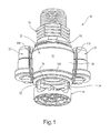
- FIGURE 1 is a lower perspective view of an exemplary but nonlimiting embodiment of the invention.
- FIGURE 2 is an upper perspective view of the sprinkler shown in Figure 1 ;
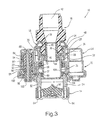
- FIGURE 3 is a cross section of the sprinkler shown in Figures 1 and 2 ;
- FIGURE 4 is a perspective view of an annular support ring taken from the sprinkler shown in Figures 1-3 ;
- FIGURE 5 is a cross section similar to Figure 3 but with the water-deflection plate moved axially downward to a position assumed under large nozzle size and/or high line pressure conditions;
- FIGURE 6 is a bottom right perspective view of the sprinkler shown in Figures 1-3 and 5 but with parts removed to better illustrate the gear drive mechanism internal to the sprinkler;
- FIGURE 7 is an enlarged detail of a part of the sprinkler illustrated in Figure 3 ;
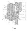
- FIGURE 8 is an enlarged perspective view of a portion of the sprinkler shown in Figure 5 ;
- FIGURE 8A is a view similar to Figure 7 , but with the sprinkler housing removed;
- FIGURE 9 is a perspective view of a stationary brake disc utilized in the sprinkler shown in Figures 1-8 ;
- FIGURE 10 is a perspective view of a brake hub utilized in the sprinkler shown in Figures 1-8 ;
- FIGURE 11 is a perspective view of a rotatable brake disc utilized in the sprinkler shown in Figures 1-8 ;
- FIGURE 12 is a bottom perspective view of an axially-moveable and rotatable sleeve component taken from the sprinkler shown in Figures 1-8 ;
- FIGURE 13 is a top right perspective view of a second exemplary but nonlimiting embodiment of the invention.
- FIGURE 14 is a front elevation view of the sprinkler shown in Figure 13 ;
- FIGURE 15 is a cross section of the sprinkler shown in Figure 14 ;
- FIGURE 16 is a cross section of a third exemplary but nonlimiting embodiment of the invention.
- a sprinkler 10 in accordance with an exemplary and nonlimiting embodiment of this disclosure includes a sprinkler body housing 12 that supports a rotatable water-deflection (or distribution) plate 14 at one end thereof.
- An adapter 16 is threaded into the sprinkler body at the opposite end thereof, with a replaceable nozzle 18 sandwiched between the adapter and the sprinkler body.
- the sprinkler body housing 12 includes a substantially cylindrical center body portion 20 and a pair of diametrically opposed, smaller side housings 22 and 24.
- the center body portion 20 of the sprinkler is formed with an inner cylindrical wall 26, spaced radially and concentrically inwardly of an outer cylindrical wall 28.
- the inner cylindrical wall 26 is formed with an upper cylindrical wall portion 30 and a lower cylindrical wall portion 32, the lower wall portion 32 having a diameter less than the upper wall portion 30.
- the upper wall portion 30 is internally threaded at 34 so as to receive external threads 36 on the lower part of the adapter 16.
- the nozzle 18 includes a cylindrical center wall 40 that forms a flow passage axially between the interior passage 42 of the adapter 16 and the nozzle orifice 44.
- a radial flange 46 is adapted to seat on the shoulder 38 with the lower end of the adapter 16 engaged with the upper surface of the flange 46 when the adapter is threaded into the body.
- a surrounding band 48 integrally formed with the nozzle, is used to provide the user with plainly visible nozzle size or other relevant information. It will be understood that the nozzle 18 is easily replaceable by removing the adapter 16, removing the nozzle and sliding a new nozzle into place, and then re-threading the adapter to the sprinkler body. This arrangement, per se, is known from commonly-owned U.S. Patent No. 5,415,348 .
- the water-deflection plate 14 is formed with a plurality of grooves 50 that are shaped and arranged in a known manner to cause the plate to rotate when a stream emitted from the nozzle orifice 44 strikes the plate and divides itself into plural streams thrown radially away from the deflection plate.
- the deflection plate 14 is supported in axially-spaced relationship to the nozzle 18 by means of a pair of struts or posts 52, 54 extending from an annular support ring 56 that is threadably mounted within a substantially cylindrical, rotatable, and axially-moveable sleeve 58 supported between the inner and outer walls of the sprinkler body, as best seen in Figures 3 and 5 .
- the annular support ring 56 is provided with a threaded portion 60 employed to secure the ring to the axially-moveable sleeve 58.
- the posts or struts 52, 54 are identical, and therefore, only one need be further described.
- Strut 52 for example, is formed with a cylindrical portion 62 that is received within the deflection plate 14.
- Portion 62 is internally threaded and adapted to receive a screw fastener 64 as shown in Figure 3 .
- the water-deflection plate 14 is secured to the sprinkler body by means of a pair of similar screws 64, threaded into the posts 52, 54.
- Those portions of the posts 52, 54 interposed between the sleeve 58 and the annular support ring 56 are formed with blade-shaped profiles 66, providing a more aerodynamic shape that facilitates rotation of the water-deflection plate 14.
- the sleeve 58 along with the deflection plate 14, is axially moveable relative to the sprinkler body housing 12.
- the end of the sleeve 58 remote from the deflection plate 14 is formed with a radially inwardly facing flange or upper bearing 68 that engages the lower cylindrical wall portion 32 a manner that, in combination with a lower sleeve bearing 69 permits sliding movement of the sleeve relative to the lower cylindrical wall portion 32 as will be described further herein below.
- a brake hub 70 in the form of an annular flanged ring, is press-fit over the lower wall portion 32 of the inner wall 26 and includes a cylindrical sleeve portion 72 and a lower radial flange 74 on which are supported a plurality of brake discs 76 to be described further below.
- a brake hub 70 in the form of an annular flanged ring, is press-fit over the lower wall portion 32 of the inner wall 26 and includes a cylindrical sleeve portion 72 and a lower radial flange 74 on which are supported a plurality of brake discs 76 to be described further below.
- a brake hub 70 in the form of an annular flanged ring, is press-fit over the lower wall portion 32 of the inner wall 26 and includes a cylindrical sleeve portion 72 and a lower radial flange 74 on which are supported a plurality of brake discs 76 to be described further below.
- axial gap 78 between the uppermost of the brake discs
- both the deflection plate 14 and the sleeve 58 rotate about the lower wall portion 32 of the sprinkler body housing.
- the water pressure (or line pressure) causes the deflection plate 14 and sleeve 58 to move axially downwardly (relative to the orientation in Figure 3 ) against the bias of an annular wave spring 82 (see Figure 8A ) interposed between the fixed brake hub 70 and the flange 68 of the sleeve 58.
- annular wave spring 82 see Figure 8A
- the viscous motor 84 includes a housing 86 in which a shaft 88 is secured for rotation relative to the housing.
- a rotor element 90 is fixed to the shaft for rotation therewith, within an internal sealed chamber 92 of the housing that is filled or at least partially filled with a viscous fluid, for example, silicone.
- the open (lower) end of the housing 86 is sealed by a bearing cap 94 and a double-lip seal 96, both held in place by a retainer 98.
- the shaft 88 extends out of the motor housing 86 and supports a first ring gear 100 on a hub 102 fixed to the shaft 88 for rotation therewith.
- Gear 100 meshes with a second ring gear 104 fixed to the lower end of the sleeve 58.
- the gear 100 can also move axially relative to the fixed gear 100 with no impact on the drive arrangement between the gears.
- the brake hub 70 is locked to the lower wall portion 32 of the inner wall 26 of the sprinkler center body portion 20 which does not rotate, and hence, the brake discs 76 resist rotation of the sleeve 58 and deflection plate 14.
- certain of the discs 76 are permitted to rotate with the sleeve 58 and others are held stationary.
- the discs 76A, B and C are held stationary by reason of radially inner flutes (or ribs) 106 engaged with axial grooves 108 (see Figure 10 ) formed on the exterior side of the cylindrical surface 72 of the hub 70.
- Intermeshed discs 76D, E and F ( Fig.
- sleeve 11 are formed with radially outer flutes or ribs 110 that are engaged with axial grooves 112 (see Fig. 12 ) formed on the inner surface of the sleeve 58.
- FIG. 13-15 another exemplary but nonlimiting implementation of a rotating sprinkler 120 is shown.
- the rotary damper (or viscous motor) 122 is located within an offset housing 124 that is not fixed to the sprinkler body 126. Rather, the housing 124 is integrated with the axially-moveable and rotatable sleeve portion 128 that is concentrically arranged about a hollow sprinkler body stem 130.
- the rotary damper swings or orbits about the elongated, hollow sprinkler stem 130 along with the deflection plate 114.
- Stem 130 is formed with an upper radial flange 132 which seats on an inner shoulder 134 on the sprinkler body 126 and is held in place by nozzle 118.
- a lower frame member 138 supports the housing 124 (including sleeve portion 128), and the deflection plate struts 140, 142 depend from frame 138.
- the frame 138 and deflection plate 114 assembly is attached to the housing 124 via a flex latch 144 and a pair of closed loops, 146 that fit over a pair of bosses 148 formed on the outer wall of the sleeve 128.
- a sleeve-frame seal 150 (o-ring or equivalent) is employed at the sleeve/frame interface.
- a brake hub 152 is fixed to the inner circumference of the stem 130, and a stem gear 154 is fixed to the outer circumference of the hub. Stem gear 154 meshes with the gear 156 that is secured to the hub 158 affixed to shaft 160.
- the damper or viscous brake mechanism is essentially identical to the earlier-described embodiment and no further description is needed here.
- the ring-shaped brake hub 152 is formed with an annular horizontal flange or shoulder 162 that supports plural, alternating rotatable and stationary brake discs 164 that interact with the sleeve wall and brake hub in the same manner as described above.
- a coil spring 166 extends between an upper edge of the brake hub 152 and an annular groove 168 in the sleeve portion 128, biasing the housing 124 and sleeve portion 128 in a vertically upward direction.
- the housing 124 With increased pressure on the deflection plate 114, the housing 124 (and sleeve portion 128) will move downwardly along the stem, against the bias of coil spring 166 until the brake discs 164 are frictionally engaged between the brake hub and the sleeve portion, further slowing rotation of the deflection plate.
- the stem seals 172, 174 and associated retainers 176, 178 are required along the stem.
- Figure 16 illustrates another alternative embodiment similar to the embodiment in Figures 1-12 but here, the rotary damper (as well as the dummy boss) has been removed.
- the component parts otherwise replicate the earlier-described embodiment, and thus similar reference numerals, with the prefix "2" added, are used to identify corresponding components, all of which function in a substantially identical manner and, therefore, need not be described again here.
- the main difference with this design is that there is no rotary damper, and therefore no gears are required.
- the intent is to let the water-deflection plate 214 rotate (spin) at a relatively high whirling speed, to facilitate greater breakup of the stream.
- This design still incorporates a pressure-compensating multi-disc friction brake (including discs 276), and spring 282) to keep the disc brake from actuating with small nozzles and low line pressures.
- the only drag is seal and bearing friction, which can be significant.
- the multi-disc friction brake is thus intended to allow the unit to spin at a relatively constant speed over a wide range of nozzles and pressures.
- Ribs 108, 110 along the interface of side housings 22, 24 with center body portion 20 also serve to channel the drool water towards the plate 14. Also, note that the water-deflection plate 14 is formed with an upper lip 112 that assists in channeling the drool onto the side streams.
Landscapes
- Nozzles (AREA)
Applications Claiming Priority (1)
| Application Number | Priority Date | Filing Date | Title |
|---|---|---|---|
| US12/536,204 US8567699B2 (en) | 2009-08-05 | 2009-08-05 | Rotary strut sprinkler |
Publications (1)
| Publication Number | Publication Date |
|---|---|
| EP2281637A1 true EP2281637A1 (fr) | 2011-02-09 |
Family
ID=42998367
Family Applications (1)
| Application Number | Title | Priority Date | Filing Date |
|---|---|---|---|
| EP10170865A Withdrawn EP2281637A1 (fr) | 2009-08-05 | 2010-07-27 | Arroseur rotatif à jambe |
Country Status (2)
| Country | Link |
|---|---|
| US (1) | US8567699B2 (fr) |
| EP (1) | EP2281637A1 (fr) |
Cited By (3)
| Publication number | Priority date | Publication date | Assignee | Title |
|---|---|---|---|---|
| CN102989608A (zh) * | 2012-12-13 | 2013-03-27 | 水利部农田灌溉研究所 | 一种四流道微灌喷头 |
| CN103586153A (zh) * | 2013-11-14 | 2014-02-19 | 哈尔滨工程大学 | 一种带有调速装置的伸缩式旋转喷头 |
| CN104402766A (zh) * | 2014-09-20 | 2015-03-11 | 中北大学 | 一种连续制备甲苯二异氰酸酯的单反射超重力装置及工艺 |
Families Citing this family (23)
| Publication number | Priority date | Publication date | Assignee | Title |
|---|---|---|---|---|
| IT1390781B1 (it) * | 2008-07-24 | 2011-09-23 | Arno Drechsel | Dispositivo diffusore di liquidi. |
| US8671949B2 (en) | 2009-06-23 | 2014-03-18 | 3M Innovative Properties Company | Headgear-earwear assembly and a method of assembling same |
| US8728211B2 (en) * | 2012-03-30 | 2014-05-20 | Alstom Technology Ltd | Nozzle for spraying liquid and a mixer comprising the nozzle |
| US9492832B2 (en) | 2013-03-14 | 2016-11-15 | Rain Bird Corporation | Sprinkler with brake assembly |
| US10350619B2 (en) | 2013-02-08 | 2019-07-16 | Rain Bird Corporation | Rotary sprinkler |
| US9314952B2 (en) | 2013-03-14 | 2016-04-19 | Rain Bird Corporation | Irrigation spray nozzle and mold assembly and method of forming nozzle |
| US9700904B2 (en) | 2014-02-07 | 2017-07-11 | Rain Bird Corporation | Sprinkler |
| USD758543S1 (en) * | 2015-05-04 | 2016-06-07 | Nelson Irrigation Corporation | Pressure regulator |
| USD758544S1 (en) * | 2015-05-04 | 2016-06-07 | Nelson Irrigation Corporation | Pressure regulator |
| WO2017049225A1 (fr) * | 2015-09-16 | 2017-03-23 | Peformance Friction Corporation | Disque/moyeu de rotor flottant muni d'un dispositif de fixation à bague de maintien |
| US10322423B2 (en) | 2016-11-22 | 2019-06-18 | Rain Bird Corporation | Rotary nozzle |
| US11154877B2 (en) | 2017-03-29 | 2021-10-26 | Rain Bird Corporation | Rotary strip nozzles |
| USD894370S1 (en) * | 2017-04-18 | 2020-08-25 | Hsin-Yung Lin | Atomization cup |
| US11511289B2 (en) | 2017-07-13 | 2022-11-29 | Rain Bird Corporation | Rotary full circle nozzles and deflectors |
| US11890634B2 (en) | 2018-11-05 | 2024-02-06 | Xcad Usa | Eddy current sprinkler dampener |
| US11154882B2 (en) | 2018-12-11 | 2021-10-26 | Nelson Irrigation Corporation | Cage design with modified struts including oriented fins |
| US11045822B2 (en) | 2019-01-02 | 2021-06-29 | Xcad Valve And Irrigation, Inc. | Speed controlled nutating sprinkler |
| US11000866B2 (en) * | 2019-01-09 | 2021-05-11 | Rain Bird Corporation | Rotary nozzles and deflectors |
| US11059056B2 (en) | 2019-02-28 | 2021-07-13 | Rain Bird Corporation | Rotary strip nozzles and deflectors |
| US11406999B2 (en) | 2019-05-10 | 2022-08-09 | Rain Bird Corporation | Irrigation nozzle with one or more grit vents |
| US11247219B2 (en) | 2019-11-22 | 2022-02-15 | Rain Bird Corporation | Reduced precipitation rate nozzle |
| CN113477427B (zh) * | 2021-07-06 | 2022-12-02 | 西北农林科技大学 | 适用于轻小型平移式喷灌机的非全圆喷洒末端低压喷头 |
| US12564848B2 (en) | 2021-09-16 | 2026-03-03 | Nelson Irrigation Corporation | Irrigation sprinkler with multiple patterns and rotation speeds |
Citations (5)
| Publication number | Priority date | Publication date | Assignee | Title |
|---|---|---|---|---|
| EP0025425A1 (fr) * | 1979-08-30 | 1981-03-18 | Österreichische Salen-Kunststoffwerk Gesellschaft m.b.H. | Arroseur |
| US5415348A (en) | 1993-08-31 | 1995-05-16 | Nelson Irrigation Corporation | Quick change and easily identifiable nozzle construction for use in modular sprinkler assembly |
| EP1426112A2 (fr) * | 2002-12-04 | 2004-06-09 | Rain Bird Corporation | Arroseur rotatif avec frein pour commander la vitesse de rotation |
| US20060006254A1 (en) * | 2004-07-07 | 2006-01-12 | Nelson Irrigation Corporation | Two-axis full-circle sprinkler |
| EP1894633A2 (fr) * | 2006-08-31 | 2008-03-05 | Nelson Irrigation Corporation | Plaque de distribution et diffuseur montés sur arbre fixe |
Family Cites Families (11)
| Publication number | Priority date | Publication date | Assignee | Title |
|---|---|---|---|---|
| US2910246A (en) * | 1953-02-19 | 1959-10-27 | Fmc Corp | Rotary sprinkler control |
| US4660766A (en) * | 1985-09-18 | 1987-04-28 | Nelson Irrigation Corporation | Rotary sprinkler head |
| USRE33823E (en) * | 1985-09-18 | 1992-02-18 | Nelson Irrigation Corporation | Rotary sprinkler head |
| US4717073A (en) * | 1986-05-02 | 1988-01-05 | The Boeing Company | Sprayer head |
| US6135364A (en) * | 1999-02-01 | 2000-10-24 | Nelson Irrigation Corporation | Rotator air management system |
| US6854668B2 (en) * | 2002-04-29 | 2005-02-15 | Victaulic Company Of America | Extended coverage ordinary hazard sprinkler system |
| US7299999B2 (en) * | 2003-04-02 | 2007-11-27 | Rain Bird Corporation | Rotating stream sprinkler with torque balanced reaction drive |
| US7954731B2 (en) * | 2003-06-04 | 2011-06-07 | Rain Bird Corporation | Low flow sprinkler |
| US7770821B2 (en) * | 2005-04-21 | 2010-08-10 | Senninger Irrigation Inc. | Irrigation sprinkler |
| US7287710B1 (en) * | 2006-07-21 | 2007-10-30 | Nelson Irrigation Corporation | Sprinkler with magnetic nutating mechanism and related method |
| US7624935B2 (en) * | 2006-08-31 | 2009-12-01 | Nelson Irrigation Corporation | Distributor plate and diffuser plate on sleeved shaft |
-
2009
- 2009-08-05 US US12/536,204 patent/US8567699B2/en active Active
-
2010
- 2010-07-27 EP EP10170865A patent/EP2281637A1/fr not_active Withdrawn
Patent Citations (5)
| Publication number | Priority date | Publication date | Assignee | Title |
|---|---|---|---|---|
| EP0025425A1 (fr) * | 1979-08-30 | 1981-03-18 | Österreichische Salen-Kunststoffwerk Gesellschaft m.b.H. | Arroseur |
| US5415348A (en) | 1993-08-31 | 1995-05-16 | Nelson Irrigation Corporation | Quick change and easily identifiable nozzle construction for use in modular sprinkler assembly |
| EP1426112A2 (fr) * | 2002-12-04 | 2004-06-09 | Rain Bird Corporation | Arroseur rotatif avec frein pour commander la vitesse de rotation |
| US20060006254A1 (en) * | 2004-07-07 | 2006-01-12 | Nelson Irrigation Corporation | Two-axis full-circle sprinkler |
| EP1894633A2 (fr) * | 2006-08-31 | 2008-03-05 | Nelson Irrigation Corporation | Plaque de distribution et diffuseur montés sur arbre fixe |
Cited By (5)
| Publication number | Priority date | Publication date | Assignee | Title |
|---|---|---|---|---|
| CN102989608A (zh) * | 2012-12-13 | 2013-03-27 | 水利部农田灌溉研究所 | 一种四流道微灌喷头 |
| CN102989608B (zh) * | 2012-12-13 | 2015-08-19 | 水利部农田灌溉研究所 | 一种四流道微灌喷头 |
| CN103586153A (zh) * | 2013-11-14 | 2014-02-19 | 哈尔滨工程大学 | 一种带有调速装置的伸缩式旋转喷头 |
| CN103586153B (zh) * | 2013-11-14 | 2015-10-28 | 哈尔滨工程大学 | 一种带有调速装置的伸缩式旋转喷头 |
| CN104402766A (zh) * | 2014-09-20 | 2015-03-11 | 中北大学 | 一种连续制备甲苯二异氰酸酯的单反射超重力装置及工艺 |
Also Published As
| Publication number | Publication date |
|---|---|
| AU2010203296A1 (en) | 2011-02-24 |
| US8567699B2 (en) | 2013-10-29 |
| US20110031332A1 (en) | 2011-02-10 |
Similar Documents
| Publication | Publication Date | Title |
|---|---|---|
| US8567699B2 (en) | Rotary strut sprinkler | |
| TWI290486B (en) | Rotating stream sprinkler with speed control brake | |
| US8991724B2 (en) | Wobbling sprinkler with viscous brake | |
| US8998107B2 (en) | Pop-up sprinkler with integrated pressure regulator and drain check | |
| US8336788B2 (en) | Dripless rotary sprinkler and related method | |
| CN102159325B (zh) | 一种液体扩散装置 | |
| US7562833B2 (en) | Sprinkler with magnetic nutating mechanism and related method | |
| US8998109B2 (en) | Sprinkler | |
| EP3311926B1 (fr) | Buse d'arc variable rotatif | |
| JP2593462B2 (ja) | 回転散水器 | |
| US7789323B2 (en) | Dual-mode sprinkler head | |
| AU2018203585B2 (en) | Sprinkler with brake assembly | |
| US20040195362A1 (en) | Rotating stream sprinkler with torque balanced reaction drive | |
| EP1915895B1 (fr) | Distributeur pour la division d'un flux principal de liquide dans plusieurs fluides partiels | |
| US12564848B2 (en) | Irrigation sprinkler with multiple patterns and rotation speeds | |
| US3598317A (en) | Rotatable sprinkler assembly | |
| RU2290261C1 (ru) | Распылитель вращающийся мелкокапельный | |
| KR20090000501U (ko) | 휴대용 연무 방제기에 적합한 클러치장치 |
Legal Events
| Date | Code | Title | Description |
|---|---|---|---|
| PUAI | Public reference made under article 153(3) epc to a published international application that has entered the european phase |
Free format text: ORIGINAL CODE: 0009012 |
|
| AK | Designated contracting states |
Kind code of ref document: A1 Designated state(s): AL AT BE BG CH CY CZ DE DK EE ES FI FR GB GR HR HU IE IS IT LI LT LU LV MC MK MT NL NO PL PT RO SE SI SK SM TR |
|
| AX | Request for extension of the european patent |
Extension state: BA ME RS |
|
| 17P | Request for examination filed |
Effective date: 20110805 |
|
| 17Q | First examination report despatched |
Effective date: 20130528 |
|
| GRAP | Despatch of communication of intention to grant a patent |
Free format text: ORIGINAL CODE: EPIDOSNIGR1 |
|
| INTG | Intention to grant announced |
Effective date: 20131219 |
|
| STAA | Information on the status of an ep patent application or granted ep patent |
Free format text: STATUS: THE APPLICATION IS DEEMED TO BE WITHDRAWN |
|
| 18D | Application deemed to be withdrawn |
Effective date: 20140430 |