EP2281643A1 - Dispositif de pliage de pièces tubulaires - Google Patents
Dispositif de pliage de pièces tubulaires Download PDFInfo
- Publication number
- EP2281643A1 EP2281643A1 EP10005589A EP10005589A EP2281643A1 EP 2281643 A1 EP2281643 A1 EP 2281643A1 EP 10005589 A EP10005589 A EP 10005589A EP 10005589 A EP10005589 A EP 10005589A EP 2281643 A1 EP2281643 A1 EP 2281643A1
- Authority
- EP
- European Patent Office
- Prior art keywords
- workpiece
- rotor
- bending
- mandrel
- arrangement according
- Prior art date
- Legal status (The legal status is an assumption and is not a legal conclusion. Google has not performed a legal analysis and makes no representation as to the accuracy of the status listed.)
- Granted
Links
Images


Classifications
-
- B—PERFORMING OPERATIONS; TRANSPORTING
- B21—MECHANICAL METAL-WORKING WITHOUT ESSENTIALLY REMOVING MATERIAL; PUNCHING METAL
- B21D—WORKING OR PROCESSING OF SHEET METAL OR METAL TUBES, RODS OR PROFILES WITHOUT ESSENTIALLY REMOVING MATERIAL; PUNCHING METAL
- B21D9/00—Bending tubes using mandrels or the like
- B21D9/04—Bending tubes using mandrels or the like the mandrel being rigid
-
- B—PERFORMING OPERATIONS; TRANSPORTING
- B21—MECHANICAL METAL-WORKING WITHOUT ESSENTIALLY REMOVING MATERIAL; PUNCHING METAL
- B21D—WORKING OR PROCESSING OF SHEET METAL OR METAL TUBES, RODS OR PROFILES WITHOUT ESSENTIALLY REMOVING MATERIAL; PUNCHING METAL
- B21D9/00—Bending tubes using mandrels or the like
- B21D9/05—Bending tubes using mandrels or the like co-operating with forming members
- B21D9/07—Bending tubes using mandrels or the like co-operating with forming members with one or more swinging forming members engaging tube ends only
- B21D9/073—Bending tubes using mandrels or the like co-operating with forming members with one or more swinging forming members engaging tube ends only with one swinging forming member
-
- B—PERFORMING OPERATIONS; TRANSPORTING
- B21—MECHANICAL METAL-WORKING WITHOUT ESSENTIALLY REMOVING MATERIAL; PUNCHING METAL
- B21D—WORKING OR PROCESSING OF SHEET METAL OR METAL TUBES, RODS OR PROFILES WITHOUT ESSENTIALLY REMOVING MATERIAL; PUNCHING METAL
- B21D9/00—Bending tubes using mandrels or the like
- B21D9/16—Auxiliary equipment, e.g. machines for filling tubes with sand
Definitions
- the invention relates to an arrangement for bending tubular workpieces, in which a workpiece is fed to a bending head for bending and is supported during bending in the bending region by means of a mandrel introduced into the workpiece from the inside, wherein the mandrel comprises a mandrel member and a rotor, movably seated in the workpiece and the rotor is longitudinally displaceable by means of a feed device in the workpiece.
- the internal mandrel assembly consists of a mandrel member secured to a mandrel bar, which in turn connects the mandrel member to a runner connected to a feed mechanism for axially displacing the mandrel member in the pipe.
- this known method usually works only with already separated to appropriate length pipes, which are fed to the bending machine in succession.
- the inner mandrel is inserted after inserting the workpiece from behind into the tube and positioned in the bending area.
- the feed device is mounted axially behind the pipe.
- EP 1 484 123 B1 a machine in which a pipe is formed from a sheet, which is then formed by bending.
- the mandrel unit is offset so far back that it engages from above into the still open profile and thus positioned the mandrel element in the bending area.
- this known method does not work with already closed profiles, such as finished pipes.
- a device in which a tube is formed from a metal sheet, which is then reshaped by bending.
- a frozen or a solidifiable material ice
- the use of liquids or other solidifiable materials is actually undesirable, not suitable for all pipe materials and also can not withstand the high pressures during bending.
- the US Pat. No. 3,891,952 A describes a device for producing ribs on tubes by rollers.
- an inner mandrel in the tube is used as a counter-holder against the rolling pressure, which is fixed axially via an outer magnet in a corresponding position.
- the inner mandrel is not used in conjunction with bending machines.
- the invention now aims to provide an arrangement for bending tubular workpieces of the type mentioned above, with the arbitrarily long pipes, even endless tubes from the coil or unilaterally tapered or otherwise shaped pipes, the insertion of the inner mandrel from behind impossible can be bent with internal mandrel, without the use of the internal mandrel device is limited by the workpiece length or the machine length.
- the rotor consists of a magnetizable material and the feed device has a corresponding to the position of the rotor outside of the workpiece position attached magnetic device, between the and the rotor, a magnetic adhesion is formed , wherein the rotor can be moved over the magnetic device in the workpiece.
- both the rotor, as well as the magnetic device of a permanent magnet arrangement which is considered within the meaning of the invention by the term "magnetizable material" as miter caught.
- the feed device is no longer mounted axially behind the workpiece (pipe), as has hitherto been the case, but is present outside the workpiece in a position corresponding to the position of the rotor.
- the present invention thus created magnetic adhesion between the magnetic device and the rotor now gives the ability to contact by a corresponding change in the magnetic field in the magnetic device, such as by a movement thereof in the longitudinal direction of the workpiece or by generating a traveling magnetic field in the axial direction of the workpiece To cause displacement of the rotor within the workpiece.
- This can be withdrawn from the coil, endless tubes as well as very long cut to length tubes or other tubes in which an insertion of the mandrel from behind is impossible. still bend with inner spine.
- the arrangement according to the invention is also of surprisingly simple construction, hardly susceptible to interference, works with a very good efficiency and is very inexpensive hestell- and can be used.
- the magnetic device is mounted displaceably in the longitudinal direction of the workpiece, for which purpose it preferably to a drive, for.
- a spindle drive o. ⁇ . Is connected. If so moved the actuator in the longitudinal direction of the workpiece causes the magnetic Frictional connection between the magnetic device and the rotor, that then also the lying inside the tube rotor (which is fixed by the magnetic frictional connection relative to the magnetic device) also moves.
- the magnetic means is disposed around the outer circumference of the tubular workpiece, advantageously consisting of two halves which are detachably secured to each other in the assembled state, the halves of which are in a diameter plane of the workpiece.
- the two halves of the magnetic device can be moved apart in this embodiment, whereby the introduction of the rotor and the mandrel element in the tube is particularly easy to carry out.
- a preferred embodiment of the invention is also the fact that the magnet assembly as well as the rotor in the longitudinal direction of the tubular workpiece are each layered by spacers of non-magnetizable material axially separated permanent magnets, each having their axially facing sides have a same polarity.
- the permanent magnets of the rotor in particular, preferably have opposite magnetic poles compared to permanent magnets of the magnetic device assigned to them on the outside of the workpiece, viewed in the axial direction of the workpiece.
- the rotor and the magnet device, along the longitudinal axis of the workpiece each comprise an even number of permanent magnets, which then ensure that the poles of the first and the last magnet are the same poles.
- the magnetic device can also be advantageously designed as an electromagnet.
- the magnetic device is formed so that in her, viewed in the axial direction of the workpiece, a migrating magnetic field is generated by which the rotor can be moved in the longitudinal direction in this according to the operation of a linear motor, without causing the magnetic device in turn should be moved.
- the magnet device must be formed significantly longer than the rotor seen in the axial direction of the workpiece. The advantage of such a structure is the fact that no further drive devices for Method of magnet assembly are more needed and the rotor can be used without any problems when the magnetic field is switched off.
- the rotor is connected to the mandrel member via a mandrel.
- a particularly advantageous embodiment of the invention is also achieved in that the mandrel element in the workpiece during the bending process reversing and / or about its longitudinal axis is rotationally movable, which can be easily achieved in the formation of the magnetic device as an electric motor by a corresponding control of the same.
- the inner mandrel element is not positioned at a specific point in the bending area during the bending process, but can be reversibly (oscillating about, oscillating or swinging) in the bending area and / or rotating about its longitudinal axis.
- Such oscillatory motions may be at a slower rate (such as to reshape bend with a mandrel) or at a high frequency (eg, to reduce friction between the inner mandrel and tube, to hammer on the bend area, or to affect the flow behavior of the tubing material ) operate.
- the radial gap between the two is chosen so small in the invention in coaxial alignment of rotor and magnetic device, that the workpiece is still free to move freely through it. Because the gap between rotor and magnetic device should be as low as possible in the interest of the greatest possible power transmission, which is why it is endeavored to keep it as small as possible; However, it should be so large that the workpiece to be machined in each case is just freely displaced through the gap formed.
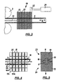
- Fig. 1 is a schematic view of a bending machine 1 for bending a tubular workpiece 2 in the form of an endless tube material from the coil 3 shown.
- the bending machine 1 shown has a straightening unit 4 with a plurality of straightening rollers 5 located in different planes and a feed unit 6 with a plurality of feed rollers 7, a separating device 8 for cutting the endless tubular workpiece 2 and a bending tool 9 with a bending mandrel 10, a Faltenglätter 11 and a Slide rail 12.
- the structure of the bending machine 1 shown so far is an example of a standard construction.
- a contactless internal mandrel device 13 is now provided here inside the tubular workpiece 2, from the in Fig. 1 only the actuating device arranged around the tubular workpiece 2 in the form of a magnetic device 14 can be seen.
- the internal mandrel device 13 may in principle be attached at any point along the tubular workpiece 2 between the coil 3 and the bending tool 9, such. B. also between the feed device 6 and the bending tool. 9
- Fig. 2 now shows a slightly enlarged, partially cut neckline Fig. 1 ,
- the entire inner mandrel device 13 can now also be seen here.
- the magnetic device 14 allows, as will be explained below in more detail, a displacement of the tubular workpiece 2 slidably mounted mandrel element 15, which in the form of z. B. a stubble, a mandrel, a ball mandrel, a spoon mandrel, a special mandrel o. ⁇ . Is formed and connected to a rotor 16 via a mandrel 17.
- the rotor 16 can be displaced in the axial direction X in the tubular workpiece 2.
- the rotor 16 and the magnetic device 14 are designed so that when coaxial arrangement of the two to be machined tubular workpiece 2 can be pushed through the remaining radial gap 18 just.
- the gap 18 between the rotor 16 and the magnetic device 14 should be as small as possible in the interest of a good and large power transmission.
- the inner mandrel can also be embodied without a mandrel rod 17, namely if the magnetic device 14 is provided directly behind the bending tool 9, in which case the mandrel element 15 passes directly into the rotor 16.
- FIG. 3 a first embodiment of magnetic device 14 and rotor 16 is shown in an inventive arrangement.
- both the rotor 16, as well as the magnetic device 14 with a plurality of axially juxtaposed X in the axial direction of permanent magnets 19 are provided, 19 spacers 20 are provided from non-magnetizable material between the individual permanent magnets.
- a drive 21 is provided, such as in the form of a pneumatic cylinder, a spindle drive o. ⁇ ., which is connected to a coupling point 22 to the magnet device 14.
- the magnetic device 14 can be moved in the axial direction X, whereby then due to the magnetic force foot and the inside of the tubular workpiece 2 lying rotor 16 (and with it the entire inner mandrel) are moved.
- This structure allows a very compact design of the magnetic device 14, but requires a separate drive device 21 and special provisions for inserting the inner mandrel, since the magnetic force can not be switched off.
- the arrangement of the polarity (north / south) of the permanent magnets 19 is in Fig. 4 shown.
- the rotor 16 consists of a first magnet 19a, which has a south pole on the left and a north pole on the right. This is followed by a spacer 20 and the second magnet 19b, but now left with its north pole and right with its south pole.
- the same pole is at the left and at the right end of the rotor 16, so that the direction of the rotor 16 when inserted into the tubular workpiece 2 does not matter.
- the permanent magnets 19c, 19d, etc. of the magnetic device 14 are in principle identical as arranged in the rotor 16, wherein the pole position opposite to the rotor 16, however, is reversed, as this Fig. 4 shows what is pointed out.
- Fig. 5 shows a possible structure for inserting the rotor 16 in the tubular workpiece 2 in a view parallel to the axial direction X.
- the magnetic device 14 consists of an upper half 23 and a lower half 24, which moved apart to release the magnetic force can be (see arrow directions), so that the inner mandrel can be introduced into the tubular workpiece 2.
- the internal mandrel device 13 is designed as a linear motor.
- windings 25 are provided, by means of which a magnetic traveling field can be generated, in the axial direction X.
- the rotor 16 is, as in the previous embodiment, provided with permanent magnets 19, but now no longer by a moving magnetic device 14, but moved by the magnetic traveling field in the axial direction X.
- the advantage of such a structure is that no further drive device for moving the magnetic device 14 is required more and the rotor 16 can be easily inserted into the tubular workpiece 2 at any time when the magnetic field is switched off.
- this structure requires a much larger footprint for achieving the same feed force as in the previous embodiment.
- the coil 3 For bending a tubular workpiece 2 from the coil 3 with an internal mandrel device 13, the coil 3 is first provided on a reel behind the bending machine 1 and inserted into the bending machine 1 between the feed rollers 7.
- the inner mandrel (mandrel element 15, mandrel rod 17 and rotor 16) is then inserted from the front into the tubular workpiece 2 until the rotor 16 is in the region of the magnetic device 14.
- the solenoid 25 is turned off or the halves 23, 24 of the magnetic device 14, as indicated by the arrows in Fig. 5 shown, ripped apart.
- the halves 23, 24 of the magnetic device are then moved together or the electromagnet 25 is activated and thus fixes the inner mandrel.
- the inner mandrel is advanced or retracted via the magnetic device 14 in the axial direction X.
- the inner mandrel must be withdrawn so far that the moving cutting blade of the separating device 8 can not collide with the mandrel element 15.
- the mandrel element 15 can support the tubular workpiece 2 in the counter-blade when cutting from the inside to keep the deformation low.
- the inner mandrel is not positioned and remains at a specific point in the bending area during the bending process, but reversely moves (oscillating, oscillating, oscillating) in the bending region and / or rotates about its longitudinal axis.
- This oscillating motion may be at a slower rate (such as to reshape the bend with a mandrel) or at a high frequency (eg, to reduce friction between the inner mandrel and tube, to hammer action on the bend area, or to influence the flow behavior of the tubing). operate.
- a particularly uniform wear on the inner mandrel can be achieved.
Landscapes
- Engineering & Computer Science (AREA)
- Mechanical Engineering (AREA)
- Bending Of Plates, Rods, And Pipes (AREA)
Applications Claiming Priority (1)
| Application Number | Priority Date | Filing Date | Title |
|---|---|---|---|
| DE102009034589A DE102009034589B3 (de) | 2009-07-24 | 2009-07-24 | Anordnung zum Biegen von rohrförmigen Werkstücken |
Publications (2)
| Publication Number | Publication Date |
|---|---|
| EP2281643A1 true EP2281643A1 (fr) | 2011-02-09 |
| EP2281643B1 EP2281643B1 (fr) | 2013-09-18 |
Family
ID=42779876
Family Applications (1)
| Application Number | Title | Priority Date | Filing Date |
|---|---|---|---|
| EP10005589.6A Active EP2281643B1 (fr) | 2009-07-24 | 2010-05-28 | Dispositif de pliage de pièces tubulaires |
Country Status (3)
| Country | Link |
|---|---|
| US (1) | US8333094B2 (fr) |
| EP (1) | EP2281643B1 (fr) |
| DE (1) | DE102009034589B3 (fr) |
Families Citing this family (3)
| Publication number | Priority date | Publication date | Assignee | Title |
|---|---|---|---|---|
| US8631671B2 (en) * | 2011-04-14 | 2014-01-21 | GM Global Technology Operations LLC | Internal mandrel and method |
| DE102011118763A1 (de) * | 2011-11-17 | 2013-05-23 | Technische Universität Dortmund | Vorrichtung und Verfahren zum Rohrbiegen von geschlossenen Rohren |
| CN117619958A (zh) * | 2023-12-23 | 2024-03-01 | 浙江赛曼斯智能科技有限公司 | 一种基于磁悬浮的弯管机弯管穿芯辅助装置 |
Citations (7)
| Publication number | Priority date | Publication date | Assignee | Title |
|---|---|---|---|---|
| US3147792A (en) * | 1961-09-25 | 1964-09-08 | Charles F Hautau | Tube and bar bending machinery |
| US3473361A (en) * | 1967-04-06 | 1969-10-21 | Teledyne Inc | Method and apparatus for bending tubing |
| US3705506A (en) * | 1971-03-31 | 1972-12-12 | Crc Crose Int Inc | Automatic positioning device |
| US3891952A (en) | 1971-05-07 | 1975-06-24 | Non Ferrous International Corp | Electromagnetic assembly resisting axial armature movement for working or finning tubing |
| DE2816840A1 (de) | 1978-03-10 | 1979-09-13 | Eaton Leonard Corp | Verfahren und einrichtung zum herstellen gebogener rohre |
| DE3739730C1 (en) | 1987-11-24 | 1988-09-01 | Klaus-Peter Dipl-Ing Uhlmann | Method for drawing seamless metal tubes |
| EP1484123B1 (fr) | 2003-06-02 | 2006-11-29 | Palima W. Ludwig & Co. | Procédé et dispositif pour fabriquer un profilé cintré |
Family Cites Families (7)
| Publication number | Priority date | Publication date | Assignee | Title |
|---|---|---|---|---|
| US2957511A (en) * | 1956-02-03 | 1960-10-25 | Reliance Electric & Eng Co | Laminated core forming machine |
| GB1434168A (en) * | 1973-04-03 | 1976-05-05 | Centre Nat Etd Spatiales | Electro-magnetic apparatus having high holding strength and low energisation response time |
| DE3805838C2 (de) * | 1987-11-24 | 1997-03-13 | Km Europa Metal Ag | Verfahren und Vorrichtung zum Ziehen von nahtlosen Metallrohren |
| US6253595B1 (en) * | 1999-09-21 | 2001-07-03 | Crc-Evans Pipeline International, Inc. | Automated pipe bending machine |
| US6526793B1 (en) * | 2000-10-25 | 2003-03-04 | Donald M. Danko | Magnetic marking and positioning system for unfinished metal bars |
| DE10338187A1 (de) * | 2003-08-12 | 2005-03-17 | Palima W.Ludwig & Co. | Verfahren und Vorrichtung zum Biegen und Umformen von Profilen durch Walz- oder Matrizenbiegen |
| US8919171B2 (en) * | 2005-03-03 | 2014-12-30 | Nippon Steel & Sumitomo Metal Corporation | Method for three-dimensionally bending workpiece and bent product |
-
2009
- 2009-07-24 DE DE102009034589A patent/DE102009034589B3/de not_active Expired - Fee Related
-
2010
- 2010-05-28 EP EP10005589.6A patent/EP2281643B1/fr active Active
- 2010-07-23 US US12/842,463 patent/US8333094B2/en active Active
Patent Citations (7)
| Publication number | Priority date | Publication date | Assignee | Title |
|---|---|---|---|---|
| US3147792A (en) * | 1961-09-25 | 1964-09-08 | Charles F Hautau | Tube and bar bending machinery |
| US3473361A (en) * | 1967-04-06 | 1969-10-21 | Teledyne Inc | Method and apparatus for bending tubing |
| US3705506A (en) * | 1971-03-31 | 1972-12-12 | Crc Crose Int Inc | Automatic positioning device |
| US3891952A (en) | 1971-05-07 | 1975-06-24 | Non Ferrous International Corp | Electromagnetic assembly resisting axial armature movement for working or finning tubing |
| DE2816840A1 (de) | 1978-03-10 | 1979-09-13 | Eaton Leonard Corp | Verfahren und einrichtung zum herstellen gebogener rohre |
| DE3739730C1 (en) | 1987-11-24 | 1988-09-01 | Klaus-Peter Dipl-Ing Uhlmann | Method for drawing seamless metal tubes |
| EP1484123B1 (fr) | 2003-06-02 | 2006-11-29 | Palima W. Ludwig & Co. | Procédé et dispositif pour fabriquer un profilé cintré |
Also Published As
| Publication number | Publication date |
|---|---|
| US20110016941A1 (en) | 2011-01-27 |
| DE102009034589B3 (de) | 2010-10-28 |
| EP2281643B1 (fr) | 2013-09-18 |
| US8333094B2 (en) | 2012-12-18 |
Similar Documents
| Publication | Publication Date | Title |
|---|---|---|
| EP2543452B1 (fr) | Dispositif de pliage pour pièces usinées en forme de tige | |
| CH652947A5 (de) | Drahtbiegemaschine. | |
| EP3645188B1 (fr) | Procédé de fabrication d'une pièce pliée et machine de pliage pour la mise en oeuvre du procédé | |
| DE2840773A1 (de) | Halte- und fuehrungskorb fuer den dorn von kontinuierlichen walzwerken mit gehaltenem dorn | |
| EP2281643B1 (fr) | Dispositif de pliage de pièces tubulaires | |
| DE102018102914A1 (de) | Vorrichtung und Verfahren zur Zuführung von Draht in eine Produktionsanlage für Maschinenelemente elektrischer Maschinen | |
| EP2255903B1 (fr) | Dispositif de refoulement de tête | |
| EP2508298A1 (fr) | Dispositif de support et d'entraînement pour un élément de soutien de tuyau | |
| EP2429730B1 (fr) | Entraînement d'avancement pour laminoir à pas de pèlerin à froid | |
| DE60007077T2 (de) | Windungsleger | |
| EP1514617A1 (fr) | Dispositif de tréfilage et méthode d'utilisation d'un dispositif de tréfilage | |
| DE69416919T2 (de) | Trennmaschine zum automatischen Trennen und Drehen von Rohren | |
| DE60111237T2 (de) | Vorrichtung zum biegen von rohren | |
| EP3487644A1 (fr) | Chariots d'étirage destinés à une machine de formage par étirage ainsi que machine de formage par étirage | |
| DE1552148B2 (de) | Biegevorrichtung zum fortlaufenden umformen eines geraden drahtes in eine wellenfoermige feder mit in verschiedenen ebenen liegenden abschnitten | |
| DE60118485T2 (de) | Vorrichtung zum Ablängen von Metallstäben inbesondere für Betonbewehrungsstahl | |
| EP2301687A1 (fr) | Procédé et dispositif de pliage de matériaux tubulaires ou en forme de tiges | |
| EP1611970A1 (fr) | Système d'enroulement et procédé de fonctionnement pour un système d'enroulement | |
| EP1914021B1 (fr) | Machine de cintrage de barres et/ou de pièces en forme de tige, en particulier de tubes et outil pour cette machine | |
| DE202008014781U1 (de) | Wickelmaschine zur gleichzeitigen Wicklung mehrerer Spulen | |
| DE102013105629A1 (de) | Ziehmaschine zum Umformen eines länglich ausgedehnten Werkstücks | |
| DE592361C (de) | Verfahren zur Erzeugung biegsamer Rohre | |
| DE2127375A1 (de) | Flüssigkeits-Impulszylinder für numerische Steuerung | |
| AT509615A1 (de) | Vorrichtung zum trennen langgestreckter werkstücke | |
| DE2935738A1 (de) | Verfahren und vorrichtung zum geradrichten eines metallstranges. |
Legal Events
| Date | Code | Title | Description |
|---|---|---|---|
| PUAI | Public reference made under article 153(3) epc to a published international application that has entered the european phase |
Free format text: ORIGINAL CODE: 0009012 |
|
| AK | Designated contracting states |
Kind code of ref document: A1 Designated state(s): AL AT BE BG CH CY CZ DE DK EE ES FI FR GB GR HR HU IE IS IT LI LT LU LV MC MK MT NL NO PL PT RO SE SI SK SM TR |
|
| AX | Request for extension of the european patent |
Extension state: BA ME RS |
|
| 17P | Request for examination filed |
Effective date: 20110128 |
|
| GRAP | Despatch of communication of intention to grant a patent |
Free format text: ORIGINAL CODE: EPIDOSNIGR1 |
|
| RIC1 | Information provided on ipc code assigned before grant |
Ipc: B21D 9/07 20060101AFI20130430BHEP Ipc: B21D 9/16 20060101ALI20130430BHEP |
|
| INTG | Intention to grant announced |
Effective date: 20130522 |
|
| GRAS | Grant fee paid |
Free format text: ORIGINAL CODE: EPIDOSNIGR3 |
|
| GRAA | (expected) grant |
Free format text: ORIGINAL CODE: 0009210 |
|
| AK | Designated contracting states |
Kind code of ref document: B1 Designated state(s): AL AT BE BG CH CY CZ DE DK EE ES FI FR GB GR HR HU IE IS IT LI LT LU LV MC MK MT NL NO PL PT RO SE SI SK SM TR |
|
| REG | Reference to a national code |
Ref country code: GB Ref legal event code: FG4D Free format text: NOT ENGLISH |
|
| REG | Reference to a national code |
Ref country code: CH Ref legal event code: EP |
|
| REG | Reference to a national code |
Ref country code: IE Ref legal event code: FG4D Free format text: LANGUAGE OF EP DOCUMENT: GERMAN |
|
| REG | Reference to a national code |
Ref country code: AT Ref legal event code: REF Ref document number: 632460 Country of ref document: AT Kind code of ref document: T Effective date: 20131015 |
|
| REG | Reference to a national code |
Ref country code: DE Ref legal event code: R096 Ref document number: 502010004749 Country of ref document: DE Effective date: 20131114 |
|
| PG25 | Lapsed in a contracting state [announced via postgrant information from national office to epo] |
Ref country code: NO Free format text: LAPSE BECAUSE OF FAILURE TO SUBMIT A TRANSLATION OF THE DESCRIPTION OR TO PAY THE FEE WITHIN THE PRESCRIBED TIME-LIMIT Effective date: 20131218 Ref country code: CY Free format text: LAPSE BECAUSE OF FAILURE TO SUBMIT A TRANSLATION OF THE DESCRIPTION OR TO PAY THE FEE WITHIN THE PRESCRIBED TIME-LIMIT Effective date: 20130918 Ref country code: LT Free format text: LAPSE BECAUSE OF FAILURE TO SUBMIT A TRANSLATION OF THE DESCRIPTION OR TO PAY THE FEE WITHIN THE PRESCRIBED TIME-LIMIT Effective date: 20130918 Ref country code: SE Free format text: LAPSE BECAUSE OF FAILURE TO SUBMIT A TRANSLATION OF THE DESCRIPTION OR TO PAY THE FEE WITHIN THE PRESCRIBED TIME-LIMIT Effective date: 20130918 Ref country code: HR Free format text: LAPSE BECAUSE OF FAILURE TO SUBMIT A TRANSLATION OF THE DESCRIPTION OR TO PAY THE FEE WITHIN THE PRESCRIBED TIME-LIMIT Effective date: 20130918 |
|
| REG | Reference to a national code |
Ref country code: NL Ref legal event code: VDEP Effective date: 20130918 |
|
| REG | Reference to a national code |
Ref country code: LT Ref legal event code: MG4D |
|
| PG25 | Lapsed in a contracting state [announced via postgrant information from national office to epo] |
Ref country code: SI Free format text: LAPSE BECAUSE OF FAILURE TO SUBMIT A TRANSLATION OF THE DESCRIPTION OR TO PAY THE FEE WITHIN THE PRESCRIBED TIME-LIMIT Effective date: 20130918 Ref country code: LV Free format text: LAPSE BECAUSE OF FAILURE TO SUBMIT A TRANSLATION OF THE DESCRIPTION OR TO PAY THE FEE WITHIN THE PRESCRIBED TIME-LIMIT Effective date: 20130918 Ref country code: GR Free format text: LAPSE BECAUSE OF FAILURE TO SUBMIT A TRANSLATION OF THE DESCRIPTION OR TO PAY THE FEE WITHIN THE PRESCRIBED TIME-LIMIT Effective date: 20131219 Ref country code: FI Free format text: LAPSE BECAUSE OF FAILURE TO SUBMIT A TRANSLATION OF THE DESCRIPTION OR TO PAY THE FEE WITHIN THE PRESCRIBED TIME-LIMIT Effective date: 20130918 |
|
| PG25 | Lapsed in a contracting state [announced via postgrant information from national office to epo] |
Ref country code: IS Free format text: LAPSE BECAUSE OF FAILURE TO SUBMIT A TRANSLATION OF THE DESCRIPTION OR TO PAY THE FEE WITHIN THE PRESCRIBED TIME-LIMIT Effective date: 20140118 Ref country code: EE Free format text: LAPSE BECAUSE OF FAILURE TO SUBMIT A TRANSLATION OF THE DESCRIPTION OR TO PAY THE FEE WITHIN THE PRESCRIBED TIME-LIMIT Effective date: 20130918 Ref country code: CZ Free format text: LAPSE BECAUSE OF FAILURE TO SUBMIT A TRANSLATION OF THE DESCRIPTION OR TO PAY THE FEE WITHIN THE PRESCRIBED TIME-LIMIT Effective date: 20130918 Ref country code: SK Free format text: LAPSE BECAUSE OF FAILURE TO SUBMIT A TRANSLATION OF THE DESCRIPTION OR TO PAY THE FEE WITHIN THE PRESCRIBED TIME-LIMIT Effective date: 20130918 Ref country code: NL Free format text: LAPSE BECAUSE OF FAILURE TO SUBMIT A TRANSLATION OF THE DESCRIPTION OR TO PAY THE FEE WITHIN THE PRESCRIBED TIME-LIMIT Effective date: 20130918 |
|
| PG25 | Lapsed in a contracting state [announced via postgrant information from national office to epo] |
Ref country code: PL Free format text: LAPSE BECAUSE OF FAILURE TO SUBMIT A TRANSLATION OF THE DESCRIPTION OR TO PAY THE FEE WITHIN THE PRESCRIBED TIME-LIMIT Effective date: 20130918 Ref country code: ES Free format text: LAPSE BECAUSE OF FAILURE TO SUBMIT A TRANSLATION OF THE DESCRIPTION OR TO PAY THE FEE WITHIN THE PRESCRIBED TIME-LIMIT Effective date: 20130918 |
|
| REG | Reference to a national code |
Ref country code: DE Ref legal event code: R097 Ref document number: 502010004749 Country of ref document: DE |
|
| PG25 | Lapsed in a contracting state [announced via postgrant information from national office to epo] |
Ref country code: PT Free format text: LAPSE BECAUSE OF FAILURE TO SUBMIT A TRANSLATION OF THE DESCRIPTION OR TO PAY THE FEE WITHIN THE PRESCRIBED TIME-LIMIT Effective date: 20140120 |
|
| PLBE | No opposition filed within time limit |
Free format text: ORIGINAL CODE: 0009261 |
|
| STAA | Information on the status of an ep patent application or granted ep patent |
Free format text: STATUS: NO OPPOSITION FILED WITHIN TIME LIMIT |
|
| 26N | No opposition filed |
Effective date: 20140619 |
|
| PG25 | Lapsed in a contracting state [announced via postgrant information from national office to epo] |
Ref country code: DK Free format text: LAPSE BECAUSE OF FAILURE TO SUBMIT A TRANSLATION OF THE DESCRIPTION OR TO PAY THE FEE WITHIN THE PRESCRIBED TIME-LIMIT Effective date: 20130918 |
|
| REG | Reference to a national code |
Ref country code: DE Ref legal event code: R097 Ref document number: 502010004749 Country of ref document: DE Effective date: 20140619 |
|
| PG25 | Lapsed in a contracting state [announced via postgrant information from national office to epo] |
Ref country code: LU Free format text: LAPSE BECAUSE OF FAILURE TO SUBMIT A TRANSLATION OF THE DESCRIPTION OR TO PAY THE FEE WITHIN THE PRESCRIBED TIME-LIMIT Effective date: 20140528 |
|
| REG | Reference to a national code |
Ref country code: CH Ref legal event code: PL |
|
| GBPC | Gb: european patent ceased through non-payment of renewal fee |
Effective date: 20140528 |
|
| PG25 | Lapsed in a contracting state [announced via postgrant information from national office to epo] |
Ref country code: LI Free format text: LAPSE BECAUSE OF NON-PAYMENT OF DUE FEES Effective date: 20140531 Ref country code: CH Free format text: LAPSE BECAUSE OF NON-PAYMENT OF DUE FEES Effective date: 20140531 Ref country code: MC Free format text: LAPSE BECAUSE OF FAILURE TO SUBMIT A TRANSLATION OF THE DESCRIPTION OR TO PAY THE FEE WITHIN THE PRESCRIBED TIME-LIMIT Effective date: 20130918 |
|
| REG | Reference to a national code |
Ref country code: IE Ref legal event code: MM4A |
|
| REG | Reference to a national code |
Ref country code: FR Ref legal event code: ST Effective date: 20150130 |
|
| PG25 | Lapsed in a contracting state [announced via postgrant information from national office to epo] |
Ref country code: IE Free format text: LAPSE BECAUSE OF NON-PAYMENT OF DUE FEES Effective date: 20140528 |
|
| PG25 | Lapsed in a contracting state [announced via postgrant information from national office to epo] |
Ref country code: GB Free format text: LAPSE BECAUSE OF NON-PAYMENT OF DUE FEES Effective date: 20140528 Ref country code: FR Free format text: LAPSE BECAUSE OF NON-PAYMENT OF DUE FEES Effective date: 20140602 |
|
| PG25 | Lapsed in a contracting state [announced via postgrant information from national office to epo] |
Ref country code: MT Free format text: LAPSE BECAUSE OF FAILURE TO SUBMIT A TRANSLATION OF THE DESCRIPTION OR TO PAY THE FEE WITHIN THE PRESCRIBED TIME-LIMIT Effective date: 20130918 |
|
| PG25 | Lapsed in a contracting state [announced via postgrant information from national office to epo] |
Ref country code: SM Free format text: LAPSE BECAUSE OF FAILURE TO SUBMIT A TRANSLATION OF THE DESCRIPTION OR TO PAY THE FEE WITHIN THE PRESCRIBED TIME-LIMIT Effective date: 20130918 |
|
| PG25 | Lapsed in a contracting state [announced via postgrant information from national office to epo] |
Ref country code: RO Free format text: LAPSE BECAUSE OF FAILURE TO SUBMIT A TRANSLATION OF THE DESCRIPTION OR TO PAY THE FEE WITHIN THE PRESCRIBED TIME-LIMIT Effective date: 20130918 |
|
| PG25 | Lapsed in a contracting state [announced via postgrant information from national office to epo] |
Ref country code: BG Free format text: LAPSE BECAUSE OF FAILURE TO SUBMIT A TRANSLATION OF THE DESCRIPTION OR TO PAY THE FEE WITHIN THE PRESCRIBED TIME-LIMIT Effective date: 20130918 |
|
| REG | Reference to a national code |
Ref country code: AT Ref legal event code: MM01 Ref document number: 632460 Country of ref document: AT Kind code of ref document: T Effective date: 20150528 |
|
| PG25 | Lapsed in a contracting state [announced via postgrant information from national office to epo] |
Ref country code: HU Free format text: LAPSE BECAUSE OF FAILURE TO SUBMIT A TRANSLATION OF THE DESCRIPTION OR TO PAY THE FEE WITHIN THE PRESCRIBED TIME-LIMIT; INVALID AB INITIO Effective date: 20100528 Ref country code: TR Free format text: LAPSE BECAUSE OF FAILURE TO SUBMIT A TRANSLATION OF THE DESCRIPTION OR TO PAY THE FEE WITHIN THE PRESCRIBED TIME-LIMIT Effective date: 20130918 Ref country code: BE Free format text: LAPSE BECAUSE OF FAILURE TO SUBMIT A TRANSLATION OF THE DESCRIPTION OR TO PAY THE FEE WITHIN THE PRESCRIBED TIME-LIMIT Effective date: 20140531 |
|
| PG25 | Lapsed in a contracting state [announced via postgrant information from national office to epo] |
Ref country code: AT Free format text: LAPSE BECAUSE OF NON-PAYMENT OF DUE FEES Effective date: 20150528 |
|
| PG25 | Lapsed in a contracting state [announced via postgrant information from national office to epo] |
Ref country code: MK Free format text: LAPSE BECAUSE OF FAILURE TO SUBMIT A TRANSLATION OF THE DESCRIPTION OR TO PAY THE FEE WITHIN THE PRESCRIBED TIME-LIMIT Effective date: 20130918 |
|
| PG25 | Lapsed in a contracting state [announced via postgrant information from national office to epo] |
Ref country code: AL Free format text: LAPSE BECAUSE OF FAILURE TO SUBMIT A TRANSLATION OF THE DESCRIPTION OR TO PAY THE FEE WITHIN THE PRESCRIBED TIME-LIMIT Effective date: 20130918 |
|
| PGFP | Annual fee paid to national office [announced via postgrant information from national office to epo] |
Ref country code: DE Payment date: 20250519 Year of fee payment: 16 |
|
| PGFP | Annual fee paid to national office [announced via postgrant information from national office to epo] |
Ref country code: IT Payment date: 20250530 Year of fee payment: 16 |