EP2281644B1 - Support d'appuie-tête - Google Patents
Support d'appuie-tête Download PDFInfo
- Publication number
- EP2281644B1 EP2281644B1 EP10172115.7A EP10172115A EP2281644B1 EP 2281644 B1 EP2281644 B1 EP 2281644B1 EP 10172115 A EP10172115 A EP 10172115A EP 2281644 B1 EP2281644 B1 EP 2281644B1
- Authority
- EP
- European Patent Office
- Prior art keywords
- reinforcing element
- holding tube
- sleeve
- headrest
- headrest support
- Prior art date
- Legal status (The legal status is an assumption and is not a legal conclusion. Google has not performed a legal analysis and makes no representation as to the accuracy of the status listed.)
- Not-in-force
Links
- 230000003014 reinforcing effect Effects 0.000 claims description 77
- 239000000463 material Substances 0.000 claims description 31
- 238000003754 machining Methods 0.000 claims description 13
- 238000005520 cutting process Methods 0.000 claims description 9
- 238000003466 welding Methods 0.000 claims description 3
- 238000004519 manufacturing process Methods 0.000 description 16
- 238000004049 embossing Methods 0.000 description 12
- 238000000034 method Methods 0.000 description 10
- 239000002184 metal Substances 0.000 description 7
- 229910052751 metal Inorganic materials 0.000 description 7
- 230000008901 benefit Effects 0.000 description 6
- 230000008569 process Effects 0.000 description 6
- 230000009466 transformation Effects 0.000 description 6
- 238000012545 processing Methods 0.000 description 5
- 238000000844 transformation Methods 0.000 description 5
- 230000003313 weakening effect Effects 0.000 description 5
- 241000209035 Ilex Species 0.000 description 4
- 238000003780 insertion Methods 0.000 description 4
- 230000037431 insertion Effects 0.000 description 4
- 238000013461 design Methods 0.000 description 3
- 238000011161 development Methods 0.000 description 3
- 244000089486 Phragmites australis subsp australis Species 0.000 description 2
- 239000000853 adhesive Substances 0.000 description 2
- 230000001070 adhesive effect Effects 0.000 description 2
- 238000005452 bending Methods 0.000 description 2
- 229910010293 ceramic material Inorganic materials 0.000 description 2
- 238000000465 moulding Methods 0.000 description 2
- 230000009467 reduction Effects 0.000 description 2
- 238000007493 shaping process Methods 0.000 description 2
- 125000006850 spacer group Chemical group 0.000 description 2
- 229920002430 Fibre-reinforced plastic Polymers 0.000 description 1
- 229910000831 Steel Inorganic materials 0.000 description 1
- 230000003321 amplification Effects 0.000 description 1
- 230000005540 biological transmission Effects 0.000 description 1
- 230000015572 biosynthetic process Effects 0.000 description 1
- 239000002131 composite material Substances 0.000 description 1
- 150000001875 compounds Chemical class 0.000 description 1
- 230000002349 favourable effect Effects 0.000 description 1
- 239000011151 fibre-reinforced plastic Substances 0.000 description 1
- 230000006872 improvement Effects 0.000 description 1
- 238000007373 indentation Methods 0.000 description 1
- 150000002739 metals Chemical class 0.000 description 1
- 238000003199 nucleic acid amplification method Methods 0.000 description 1
- 238000005457 optimization Methods 0.000 description 1
- 239000004033 plastic Substances 0.000 description 1
- 229920003023 plastic Polymers 0.000 description 1
- 238000002360 preparation method Methods 0.000 description 1
- 239000002994 raw material Substances 0.000 description 1
- 230000002787 reinforcement Effects 0.000 description 1
- 238000005096 rolling process Methods 0.000 description 1
- 239000010959 steel Substances 0.000 description 1
Images



Classifications
-
- B—PERFORMING OPERATIONS; TRANSPORTING
- B21—MECHANICAL METAL-WORKING WITHOUT ESSENTIALLY REMOVING MATERIAL; PUNCHING METAL
- B21D—WORKING OR PROCESSING OF SHEET METAL OR METAL TUBES, RODS OR PROFILES WITHOUT ESSENTIALLY REMOVING MATERIAL; PUNCHING METAL
- B21D39/00—Application of procedures in order to connect objects or parts, e.g. coating with sheet metal otherwise than by plating; Tube expanders
- B21D39/04—Application of procedures in order to connect objects or parts, e.g. coating with sheet metal otherwise than by plating; Tube expanders of tubes with tubes; of tubes with rods
-
- B—PERFORMING OPERATIONS; TRANSPORTING
- B21—MECHANICAL METAL-WORKING WITHOUT ESSENTIALLY REMOVING MATERIAL; PUNCHING METAL
- B21D—WORKING OR PROCESSING OF SHEET METAL OR METAL TUBES, RODS OR PROFILES WITHOUT ESSENTIALLY REMOVING MATERIAL; PUNCHING METAL
- B21D17/00—Forming single grooves in sheet metal or tubular or hollow articles
- B21D17/02—Forming single grooves in sheet metal or tubular or hollow articles by pressing
-
- B—PERFORMING OPERATIONS; TRANSPORTING
- B21—MECHANICAL METAL-WORKING WITHOUT ESSENTIALLY REMOVING MATERIAL; PUNCHING METAL
- B21D—WORKING OR PROCESSING OF SHEET METAL OR METAL TUBES, RODS OR PROFILES WITHOUT ESSENTIALLY REMOVING MATERIAL; PUNCHING METAL
- B21D49/00—Sheathing or stiffening objects
- B21D49/005—Hollow objects
-
- B—PERFORMING OPERATIONS; TRANSPORTING
- B23—MACHINE TOOLS; METAL-WORKING NOT OTHERWISE PROVIDED FOR
- B23P—METAL-WORKING NOT OTHERWISE PROVIDED FOR; COMBINED OPERATIONS; UNIVERSAL MACHINE TOOLS
- B23P11/00—Connecting or disconnecting metal parts or objects by metal-working techniques not otherwise provided for
- B23P11/005—Connecting or disconnecting metal parts or objects by metal-working techniques not otherwise provided for by expanding or crimping
-
- B—PERFORMING OPERATIONS; TRANSPORTING
- B60—VEHICLES IN GENERAL
- B60N—SEATS SPECIALLY ADAPTED FOR VEHICLES; VEHICLE PASSENGER ACCOMMODATION NOT OTHERWISE PROVIDED FOR
- B60N2/00—Seats specially adapted for vehicles; Arrangement or mounting of seats in vehicles
- B60N2/80—Head-rests
-
- B—PERFORMING OPERATIONS; TRANSPORTING
- B60—VEHICLES IN GENERAL
- B60N—SEATS SPECIALLY ADAPTED FOR VEHICLES; VEHICLE PASSENGER ACCOMMODATION NOT OTHERWISE PROVIDED FOR
- B60N2/00—Seats specially adapted for vehicles; Arrangement or mounting of seats in vehicles
- B60N2/80—Head-rests
- B60N2/806—Head-rests movable or adjustable
- B60N2/809—Head-rests movable or adjustable vertically slidable
- B60N2/812—Head-rests movable or adjustable vertically slidable characterised by their locking devices
- B60N2/818—Head-rests movable or adjustable vertically slidable characterised by their locking devices with stepwise positioning
-
- Y—GENERAL TAGGING OF NEW TECHNOLOGICAL DEVELOPMENTS; GENERAL TAGGING OF CROSS-SECTIONAL TECHNOLOGIES SPANNING OVER SEVERAL SECTIONS OF THE IPC; TECHNICAL SUBJECTS COVERED BY FORMER USPC CROSS-REFERENCE ART COLLECTIONS [XRACs] AND DIGESTS
- Y10—TECHNICAL SUBJECTS COVERED BY FORMER USPC
- Y10T—TECHNICAL SUBJECTS COVERED BY FORMER US CLASSIFICATION
- Y10T29/00—Metal working
- Y10T29/49—Method of mechanical manufacture
- Y10T29/49826—Assembling or joining
Definitions
- the invention relates to headrest support with a holding tube for receiving a head support member and a method for producing the headrest support and a headrest with a headrest support.
- Headrest supports are predominantly made of U-shaped bent, usually welded by welding steel strip tubes, hereinafter called retaining tube, formed so that they have two legs with free ends and a connecting portion arranged therebetween, which serves to accommodate the padded headrest usually. With the protruding from the headrest legs of this holding tubes headrest can be fastened to a vehicle seat, wherein the legs are arranged in corresponding receptacles on the vehicle seat.
- the holding tubes must meet predetermined strength properties so that they withstand the loads occurring in the event of a vehicle accident.
- the intensity of the load varies over the length of the holding tube.
- individual portions of the holding tube in the event of a crash significantly higher loads than those areas that are arranged, for example.
- an interpretation of the entire holding tube according to the largest load occurring only isolated would ensure sufficient stability, however, requires a high material usage which in turn leads to high costs.
- the holding tubes so that they can be used as a headrest support, a number of forming operations, which lead to a structural weakening of the holding tube and thus to a reduction in stability.
- the reshaped areas are therefore particularly critical areas.
- the forming processes include, among other things, the introduction of catch marks on at least one leg of the holding tube, so that the headrest can be fixed relative to the vehicle seat in more than one position is.
- the latching marks can be formed, for example, by recesses in the form of notches, which are introduced into the holding tube and cooperate with latching means on the vehicle seat. In most cases, a plurality of notches are arranged at intervals on a leg, so that the headrest can be positioned at a variable distance from the vehicle seat.
- the notches which may be both flat so that the notch root is in the tube wall, as well as deep, so that the notch bottom is lower than the tube wall, as well as other forming operations such as bending, result in structural weakening of the holding ear.
- the DE 10 2007 033 604 discloses a headrest support which, with minimized weight, meets the strength requirements for headrest supports used in particular in motor vehicles.
- the tube wall of the holder tube has sections of different material thickness. Sections of greater material thickness are provided where in the event of a crash high loads are expected or notches or recesses are to be attached. These portions of greater material thickness are produced during rolling of the raw material for the holding tubes. The thicker sections may have the notches required to position the finished headrest on the seat.
- Headrest supports having support tubes of varying wall thicknesses, and with the recesses mounted on portions of greater thickness, are lighter and stronger than conventional headrest supports. Under load they deform much less than headrest supports, which have the same wall thickness throughout. However, it must be known even before the preparation of the holding tubes, where exactly sections of greater material thickness are to be arranged. Furthermore, then ensure that the holding tubes are used exactly (bent or interconnected), that there is sufficient wall thickness, where the highest loads occur, or a notch or other transformations are to be attached. This lacks the necessary simplicity and flexibility in the production.
- the DE 197 34 712 discloses a tubular headrest support obtained by insertion a wire section is reinforced.
- the invention has for its object to provide a headrest support and a headrest, which have a high stability with a low weight.
- the invention solves the problem by a headrest support with the features of claim 1.
- the headrest support according to the invention has a holding tube for receiving a head support element, wherein a reinforcing element is arranged within the holding tube.
- a reinforcing element is formed by a hollow body, in particular a sleeve.
- the holding tube of the headrest support which in addition to the holding tube also have other components, but can also consist only of the holding tube, sections at least one reinforcing element.
- the reinforcing element is arranged within the holding tube in a region for which a higher stability is required compared with the rest of the holding tube.
- the invention has the advantage that a structural reinforcement of particularly stressed areas can take place independently of the production of the tubes provided for the holder tubes. This makes it possible for the holding tubes to use standard tubes for the production of the headrest support, which has a significant cost advantage.
- the use of one or more reinforcing elements allows the selective amplification of individual regions, wherein also the reinforcing elements can be selected independently of each other according to the gain to be achieved. There is no need to reinforce a wide section of the pipe wall to accommodate a variety of designs.
- the reinforcing element is arranged in the region of a deformed portion of the holding tube. Accordingly, the reinforcing element is arranged in a region of the holding tube, which in the manufacture of the headrest support a forming process, for example, the production of a bend or the introduction of a recess such as a notch, subject.
- the holding tube is formed from a straight tubular element, which is converted according to the structural specifications for the headrest support. Essential forming steps include, for example, the production of the bends and the introduction of the notches.
- the arrangement of the reinforcing elements is usually carried out before performing the forming operations, but can also, if technically possible, carried out after the forming. In the case of several different transformations, it is possible to selectively reinforce them, taking into account the respective loads occurring and the degree of weakening resulting from the deformation.
- the reinforcing element is formed by a hollow body, in particular a sleeve.
- a hollow body in particular a sleeve.
- This embodiment of the invention makes it possible to reduce the weight of the headrest support.
- the required gain can be set very accurately, so that the weight is increased only to the extent necessary.
- the hollow body, in particular the sleeve can be produced particularly inexpensively, for example by cutting off individual elements of a pipe.
- connection of the reinforcing element with the holding tube is basically arbitrary, which may be glued or welded, for example, with the holding tube. According to a development of the invention, however, the reinforcing element is non-positively and / or positively connected to the holding tube. This connection is particularly easy to implement.
- the reinforcing element can be fitted into the holding tube, which in addition to a high positional safety also has the advantage that no additional, u. U. weakening deformation of the holding tube to the arrangement of the reinforcing element is required.
- the shape of the reinforcing element can be chosen freely taking into account the gain to be achieved and in terms of weight.
- the reinforcing element may have a polygonal, in particular quadrangular or polygonal or elliptical shape, which is detached from the cross section of the holding tube adapted to the loads occurring.
- the reinforcing element has a shape adapted to the shape of the deformed section, in particular a cross section adapted to the cross section of the deformed section.
- the contour of the reinforcing element corresponds to the shape of the deformed area.
- the contour can result from the fact that the reinforcing element, as provided according to a further embodiment of the invention, also undergoes the forming process of the holding tube, in which the reinforcing element is arranged prior to forming. But it is also possible to use a reinforcing element, which was previously formed according to the forming to be achieved. This results in the advantage that the reinforcing element supports the shaping during the forming in which it acts as a die.
- the deformation of the holding tube can take place in any desired manner, after the reinforcing element compensates for the weakening resulting from the deformation.
- the deformed portion is formed by machining and / or non-chipping processing of the holding tube.
- These machining forms are particularly suitable for the production of recesses, wherein a non-cutting machining, for. B. embossing for this is particularly preferred because it can be worked without loss.
- machining processes can also be used without further ado.
- the reinforcing element can basically be used on all deformed areas of the holding tube. These also include those areas which are provided, for example, for the arrangement of attachments with a bore, holder, thread or the like. However, the reinforcing element is particularly preferably arranged in flattened regions of the holding tube and / or in the region of bends, indentations or recesses, after these regions are subjected to particularly high loads, in particular in the event of a crash.
- the arrangement of the reinforcing element according to the invention can, as already described above, take place both before and after the deformation of the holding tube.
- the deformation for the production of the deformed portion also extends to the reinforcing member, a prior arrangement inside the holder tube is inevitably required.
- This embodiment ensures a secure arrangement of the reinforcing element in the holding tube, after a positive connection is achieved by the co-deformation. In this respect, can be dispensed with a different definition of the reinforcing element on the holding tube. Furthermore, a good power transmission is ensured.
- the reinforcing element can be used per se at any point of the tube, at the transformations, z. B. recesses are provided. Particularly preferably, the reinforcing elements are used where load calculations show that the material of the pipe wall is e.g. after notching sufficient strength ensured. In general, this is the case where particularly deep recesses or notches are to be attached. According to a particularly advantageous embodiment of the invention, the recess can deform the wall of the tube so far that it extends into the reinforcing element or the recess can pass through the tube wall and extend into the reinforcing element. In the case of making a notch, the notch root, the location of the deepest notch, then lies in the reinforcing element inserted into the tube. The latter is especially the case when the recess is produced by machining. However, the recess may also extend into the reinforcing element, if they are by chipless machining, for. B. is produced by embossing.
- the reinforcing element is usually made like the holding tube made of metal. According to an advantageous embodiment of the invention, however, the reinforcing element is formed from a deviating from the material of the holding tube material. Different materials may be other metals but also other materials such as ceramic materials, plastics, fiber-reinforced plastics or other composites. The use of different materials allows the use of a wide range of differently designed reinforcing elements, which further optimization in terms of cost and weight is possible. Also can be for different Use portions of the holding tube in shape and material different reinforcing elements, which are adapted to the respective loads.
- This embodiment makes it possible, for example, to provide a standard tube in the bearing, in which the reinforcing element is used made of different material, depending on how the headrest support is executed.
- the material can be selected according to weight, machinability or strength.
- the material of the holding tube may be stronger or denser than the material of the reinforcing element.
- the material of the reinforcing element may be stronger or denser than the material of the holding tube.
- a high-strength material for the holding tube can be selected, so that then lightweight reinforcing elements in the form of transformations, for example. Notches are used, which only make a small contribution to the strength in the notches.
- z. B. a relatively soft holding tube with low strength are used, which is then reinforced in the notches by a particularly strong, stiffening acting reinforcing element.
- the reinforcing element which is inserted into the holding tube, may be tight.
- the reinforcing element may be dimensioned to 50% or half the length of the recess. Length here is the extension of the holding tube in the longitudinal axis. Even with such a tightly sized reinforcing element, a significant improvement in the strength of the headrest support can be achieved. However, it is preferred that the reinforcing element corresponds at least to the length of the recess.
- the reinforcing element for example the sleeve
- the reinforcing element can have a closed circumference.
- the radius of the reinforcing element is often dimensioned so that the reinforcing element can be moved in the holding tube.
- the reinforcing element has a slot which advantageously extends in its longitudinal direction.
- the reinforcing element is provided with a groove which is slightly larger than the dimensions of the holding tube, for example. From a band, forming weld. It is preferred if the slot the Wall of a sleeve completely penetrated or if it has at least the length of the radius of a reinforcing element.
- the holder tube of the support element according to the invention usually has a weld.
- the weld slightly reduces the diameter of the holding tube, often by fractions of a millimeter. However, this reduction is sufficient to the unhindered movement of molds, z. B. a mandrel, which are introduced into the tube to z. B. to produce a deformation such as a notch.
- the weld usually proves to be a region of reduced strength. Notches can not be easily attached in the area of the weld.
- the slot of the reinforcing element is aligned with the weld.
- the weld seam can serve as a guide for the reinforcing element.
- the material of the reinforcing element reinforces the holding tube also in the region of the weld seam, so that a deformation, such as, for example, is achieved. a recess can now be attached without regard to the position of the weld.
- the reinforcing element acts like a spacer because z.
- a mandrel is now supported during embossing against a sleeve and tuned to the inner diameter. The sleeve has no weld, so that the mandrel can be moved out of the holding tube trouble-free after completion of the embossing process.
- the invention relates to a headrest having a headrest support according to one of claims 1 to 8.
- the inventive method allows the production of the headrest support according to the invention with a few steps. Using only two components, this can be made individually and flexibly, because the specifications for aligning the reinforcing element and for the design of the transformations, for example, recess can be changed with a few measures.
- the method steps can basically be carried out in any desired sequence.
- the alignment of the reinforcing element in the holding tube that is the positioning at the point at which the deformation is performed, for example. A bend is made or a recess is to be attached, done directly in connection with the production of the recess. But this is not mandatory.
- the attachment of the notches need not be simultaneous.
- cutting or non-cutting tools can be used to produce the recess.
- Particularly preferred is the generation of the notch by embossing.
- a mandrel is inserted into the holding tube, which cooperates with a die, so that under pressure the notch is produced without cutting and loss.
- machining processes may prove useful.
- a sleeve is placed on the mandrel and introduced into the holding tube to a depth in which the reinforcing element is located below the recess to be introduced into the pipe wall.
- the embossing tool closes around the tube wall, exerts pressure on the mandrel and a notch is embossed.
- the mandrel is withdrawn from the holding tube.
- a sleeve closed at the end, a plug can be positioned in a holding tube by means of a punch.
- the notch is then made with a cutting tool.
- the stamp is withdrawn at the latest after making the score. If the plug is fixed in the holding tube, for example because it is arranged in a form-fitting manner, the stamp can be withdrawn before shaping the recess. This speeds up the processing.
- the stamp can be the stopper during the insertion of the notch, for example, with an adhesive bond whose bond strength is weaker than the compound that is generated by the introduction of the notch.
- the punch can then be withdrawn after the notch is made. The weaker bond dissolves here rather than the connection of the plug to the holding tube.
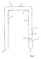
- Fig. 1 shows a headrest support 2 for seats, especially for vehicle seats.
- the headrest support 2 consists of a holding tube 4 made of metal with a diameter of 12 mm and a wall thickness of 1 mm. It is roughly U-shaped. It is adapted to receive a headrest (not shown) at the portion 6 which connects the two legs 8, 8 'of the U.
- the headrest is connected to the headrest support 2 by means of detents, screws or other known connections.
- the free ends 10, 10 'of the legs 8, 8' of the headrest support 2 are inserted into the seat back. They connect the seat, here a vehicle seat, with the headrest.
- a leg 8 is provided with recesses or notches 12, 14. These notches 12, 14 are of different shape.
- a series of flat notches or grooves 12 (notch depth less than 1 mm) is closed to the free end 10 of the leg 8 with a deep notch 14.
- the deepest point of this notch, the notch base 16, is deeper than the thickness of the pipe wall, ie, greater than 1 mm.
- This notch is V-shaped and serves to lock the support member 2 on the vehicle seat. Locking is accomplished by a latch mounted in the seat back which is biased by a spring and which engages notches 12 or 14. With the flat notches 12 can be manually adjusted the distance of the headrest to the vehicle seat.
- the deep notch 14 locks the headrest. The bolt engages so far in this notch that unlocking is only possible by the bolt is specially retracted.
- a sleeve 18 is arranged in the holding tube 4.
- the sleeve 18 is made of metal. It is 1.5 times as long as the notch 14, whose length is 7 mm.
- no sleeves 18 or plugs are arranged, since the strength of the pipe wall is sufficiently high so that the notches 12 do not weaken the pipe wall so much that it deforms under high load.
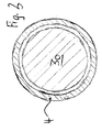
- Fig. 2a shows a schematic representation of the cross section of a headrest support 2 according to the invention Fig. 1 above the notch 14.
- the holding tube 4 has a sleeve 18 arranged therein.
- the tube wall 20 has a thickness of 1mm, it is made of metal. Other materials can be used, provided their strength properties and processing properties are suitable. Since sleeves 18 are mainly used when the notches are formed by chipless machining, sleeves 18 are preferred, which can be deformed by embossing.
- the sleeve 18 is arranged concentrically in the holding tube 4.
- the representation of the figures is not to scale; the fit is chosen so that the sleeve 18 can be moved in the holding tube 4.
- the wall thickness of the sleeve 18 is 0.5 mm.
- the material of the sleeve 18 has a higher strength than the material of the holding tube 4.
- the wall thickness of the sleeve 18 can be chosen freely according to the requirements of the strength and the weight.
- the length of the sleeve 18 can also be freely selected within wide limits.
- the sleeve 18 must give the region of the notch at least such a strength that the given load capacity is given. Often this is 0.5 times the length of the notch.
- the sleeve 18 can easily be as long as it fits into the holding tube 4 is to be inserted.
- the length of the sleeve 18 will be limited by the fact that the cost of the material and the weight of the headrest support 2 should be kept as low as possible.
- the sleeve 18 will often be longer than the notch to stabilize the tube wall in the region of the notch fitting. This has a favorable effect on the load capacity.
- Fig. 2b shows a preferred embodiment of the headrest support 2 according to the invention
- the support tube 4 is formed from a rolled, originally rectangular metal strip.
- the abutting edges were then welded, forming a weld 22 in the holding tube 4.
- the weld is about 0.5 mm wide and about 0.3 mm high.
- the weld 22 always had to be in the vicinity of the notch or groove 12, 14. Only then was it possible to remove the mandrel which, in the two-part embossing tool, forms the counterpart to the die arranged in the holding tube 4, after the recess 12, 14 has been produced, to be removed again from the holding tube 4 by turning.
- a slotted sleeve 18 used the slot 24 is suitably arranged in the region of the weld 22.
- the sleeve 18 is then passed through the weld 22.
- the sleeve 18 acts like a spacer during an embossing process. It now makes it possible to produce the recess 12, 14 wherever it is desired.
- an alignment of the notch 12, 14 with respect to the weld 22 is no longer necessary. It will be clear that, for this reason, a sleeve 18 can also be usefully used to produce a flat notch 12.
- slotted sleeve 18 is biased in the holding tube 4.
- the sleeve 18 is rolled from a board or any rectangular piece of metal. The resulting slot is not closed as in the welding of the holding tube 4.
- the width of the slot 24 and thus the circumference of the sleeve 18 is chosen to be greater than the inner diameter of the holding tube 4.
- the sleeve 18 is compressed prior to introduction into the holding tube 4, the width of the slot 24 is thus reduced, possibly overlap the ends of the sleeve 18 each other even.
- the sleeve 18 is biased Position introduced into the holding tube 4, z. B. with a holding tool or with the help of the mandrel.
- the sleeve 18 is released at the predetermined location in the holding tube 4, it relaxes until it rests against the inner wall 26 of the holding tube 4.
- the sleeve 18 is now positively connected to the holding tube 4.
- the advantage here is that the notch 12, 14 does not have to be made immediately.
- the holding tube 4 can be easily manipulated, z. B. be bent.
- the sleeve 18 is fixed, the shapes of the recess 12, 14 can be made later.
- Fig. 2c shows a section of a holding tube 4 with a sleeve 18 inserted therein and a U-shaped notch 14.
- the notch 14 is deeply formed.
- the notch base 16 is lower than the tube wall 20 and even deeper than the wall thickness of the sleeve 18.
- Pipe wall 20 and sleeve 18 are far deformed and now interlock. If the material of the sleeve 18 and the tube wall is sufficiently deformable, a notch can easily be made so deep. However, most of the notch depth is in the range of the wall thickness of the sleeve 18, so that the inner surface 28 of the sleeve 18 is not deformed.
- the design freedom in the formation of the notch is essentially determined by the material used.
- Fig. 3 shows a holding tube 4 having disposed therein a thick-walled, closed-end sleeve, with a plug 30.
- the plug is made of ceramic material. Since the plug 30 largely fills the cross-section of the holding tube 4, it is not possible to produce the recess 12, 14 without cutting, because no space is available for compressing the material. In addition, the material is not suitable for deformation. Here, however, a notch geometry is to be generated, which can not be produced with sufficient precision by means of embossing. By machining or material-removing machining, however, the desired notch geometry can be created here. Slicing, grinding or other material removal methods can be easily used. In order to ensure a trouble-free processing, the plug can be glued in the tube, either by first adhesive surfaces or points are attached in the holding tube 4 or by the plug is glued.
- a graft may also be provided with a slit, allowing the insertion and fixing of the graft is simplified.
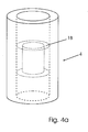
- a portion of a holding tube 4 is shown with a reinforcing element disposed therein before forming the holding tube 4.
- the reinforcing element may, as in Fig. 4a illustrated, may be formed as a sleeve 18 having a circular cross section, wherein the outer cross section of the sleeve 18 is adapted to the inner cross section of the holding tube 4.
- the reinforcing element may also have different configurations.
- a further embodiment of the reinforcing element is in Fig. 4b illustrated, in which the reinforcing element is designed as a sleeve 18a with a square cross-section.
- the headrest support according to the invention is lighter than known from the prior art support elements. At the same time the production is simple and flexible, because usually already another sleeve 18 or another plug 30 is sufficient if another support element to be produced.
- the inventively proposed insertion of a reinforcing element at the point where a transformation, for example. A recess is to be introduced, is sufficient to ensure despite deep notches sufficient strength, the deformation under high load, z. B. in an impact prevented.
- a headrest support may have both sleeves and grafts; These reinforcing elements may also be included multiple times in a headrest support.
Landscapes
- Engineering & Computer Science (AREA)
- Mechanical Engineering (AREA)
- Aviation & Aerospace Engineering (AREA)
- Transportation (AREA)
- Chair Legs, Seat Parts, And Backrests (AREA)
- Seats For Vehicles (AREA)
Claims (8)
- Support d'appuie-tête (2) avec un tube de soutien (4) destiné à recevoir un élément d'appuie-tête, dans lequel, à l'intérieur du tube de soutien (4), est disposé un élément de renforcement qui est formé par un corps creux, en particulier un manchon (18), caractérisé en ce que le corps creux présente une fente (24) s'étendant dans sa direction axiale longitudinale, laquelle fente est alignée sur une soudure (22) du tube de soutien.
- Support d'appuie-tête selon la revendication 1, caractérisé en ce que l'élément de renforcement est disposé dans la zone d'un segment formé du tube de soutien.
- Support d'appuie-tête selon une des revendications précédentes, caractérisé en ce que l'élément de renforcement est relié par complémentarité de force et/ou de forme au tube de soutien.
- Support d'appuie-tête selon une des revendications précédentes, caractérisé en ce que l'élément de renforcement présente une forme adaptée à la forme du segment formé, en particulier une section transversale adaptée à la section transversale de la zone formée.
- Support d'appuie-tête selon une des revendications précédentes, caractérisé en ce que le segment formé est façonné par usinage par enlèvement de copeaux et/ou sans enlèvement de copeaux du tube de soutien.
- Support d'appuie-tête selon une des revendications précédentes, caractérisé en ce que l'élément de renforcement est disposé dans des zones aplaties du tube de soutien et/ou dans la zone des courbures, rainures ou évidements.
- Support d'appuie-tête selon une des revendications précédentes, caractérisé en ce que le formage pour fabriquer le segment formé se projette sur l'élément de renforcement.
- Support d'appuie-tête selon une des revendications précédentes, caractérisé en ce que l'élément de renforcement est formé d'un matériau différent du matériau du tube de soutien.
Priority Applications (2)
| Application Number | Priority Date | Filing Date | Title |
|---|---|---|---|
| PL10172115T PL2281644T4 (pl) | 2009-08-07 | 2010-08-06 | Wspornik zagłówka |
| SI201030340T SI2281644T1 (sl) | 2009-08-07 | 2010-08-06 | Nosilec naslona za glavo |
Applications Claiming Priority (2)
| Application Number | Priority Date | Filing Date | Title |
|---|---|---|---|
| DE102009036523 | 2009-08-07 | ||
| DE102009047020A DE102009047020A1 (de) | 2009-08-07 | 2009-11-23 | Kopfstützenträger |
Publications (2)
| Publication Number | Publication Date |
|---|---|
| EP2281644A1 EP2281644A1 (fr) | 2011-02-09 |
| EP2281644B1 true EP2281644B1 (fr) | 2013-06-19 |
Family
ID=43064630
Family Applications (1)
| Application Number | Title | Priority Date | Filing Date |
|---|---|---|---|
| EP10172115.7A Not-in-force EP2281644B1 (fr) | 2009-08-07 | 2010-08-06 | Support d'appuie-tête |
Country Status (7)
| Country | Link |
|---|---|
| US (1) | US8356863B2 (fr) |
| EP (1) | EP2281644B1 (fr) |
| CA (1) | CA2712311A1 (fr) |
| DE (1) | DE102009047020A1 (fr) |
| ES (1) | ES2423594T3 (fr) |
| PL (1) | PL2281644T4 (fr) |
| SI (1) | SI2281644T1 (fr) |
Cited By (1)
| Publication number | Priority date | Publication date | Assignee | Title |
|---|---|---|---|---|
| DE102014002233B3 (de) * | 2014-02-21 | 2015-03-19 | Grammer Aktiengesellschaft | Tragvorrichtung für eine Kopfstütze und Verfahren zur Herstellung einer Tragvorrichtung für eine Kopfstütze |
Families Citing this family (12)
| Publication number | Priority date | Publication date | Assignee | Title |
|---|---|---|---|---|
| FR2991893B1 (fr) * | 2012-06-15 | 2015-01-02 | Numalliance | Procede de crantage de tube, et machine de crantage associee |
| US20150231997A1 (en) * | 2012-09-03 | 2015-08-20 | Ts Tech Co., Ltd. | Vehicle seat, and seat frame for vehicle seat |
| GB2517978A (en) * | 2013-09-09 | 2015-03-11 | Mahle Int Gmbh | Bearing shell |
| US9890298B2 (en) * | 2013-12-31 | 2018-02-13 | Saint-Gobain Performance Plastics Corporation | Composite bearings having a polyimide matrix |
| JP6049659B2 (ja) * | 2014-06-18 | 2016-12-21 | 理研精工株式会社 | 金属管表面の凹溝形成方法および金属管表面の凹溝形成装置 |
| JP6764854B2 (ja) * | 2015-02-24 | 2020-10-07 | 株式会社フジクラ | フェルール、及び、光ファイバ付きフェルールの製造方法 |
| JP6787333B2 (ja) * | 2015-09-30 | 2020-11-18 | 東海化成工業株式会社 | ヘッドレスト用ステー |
| DE102015016657A1 (de) * | 2015-12-19 | 2017-07-06 | GM Global Technology Operations LLC (n. d. Ges. d. Staates Delaware) | Kopfstützenanordung für ein Kraftfahrzeug |
| FR3047208B1 (fr) * | 2016-01-29 | 2019-05-03 | Faurecia Sieges D'automobile | Broche d'appui-tete et appui-tete de siege |
| JP7269629B2 (ja) * | 2019-06-25 | 2023-05-09 | 松本工業株式会社 | ヘッドレストスティ |
| CN216709111U (zh) * | 2021-11-25 | 2022-06-10 | 广州荒井汽车零部件有限公司 | 头枕支架和座椅头枕 |
| JP2024044172A (ja) * | 2022-09-20 | 2024-04-02 | 日本発條株式会社 | ヘッドレストステー及びその抜け止め構造 |
Family Cites Families (13)
| Publication number | Priority date | Publication date | Assignee | Title |
|---|---|---|---|---|
| DE9202846U1 (de) * | 1992-03-04 | 1992-05-21 | R. Schmidt GmbH, 5940 Lennestadt | Raststange für eine Kopfstütze für Kfz.-Sitze |
| JP3373953B2 (ja) * | 1994-09-22 | 2003-02-04 | 株式会社林スプリング製作所 | 支持棒の製造方法及び製造装置 |
| JP2943051B2 (ja) * | 1995-02-21 | 1999-08-30 | 池田物産株式会社 | 可動ヘッドレスト |
| US5816658A (en) * | 1997-05-23 | 1998-10-06 | Flexsteel Industries, Inc. | Head rest lock |
| DE19734712A1 (de) * | 1997-08-11 | 1999-02-18 | Kohlhage Verbindungstechnik Gm | Arretierungsvorrichtung |
| FR2816857B1 (fr) * | 2000-11-20 | 2003-02-28 | Faurecia Sieges Automobile | Procede et dispositif de crantage d'un tube d'armature pour un siege de vehicule automobile, notamment un tube d'armature d'appuie-tete |
| US6631956B2 (en) | 2001-07-26 | 2003-10-14 | Lear Corporation | Headrest support rod with plastic sleeves |
| US6641219B2 (en) * | 2001-12-18 | 2003-11-04 | E.R. Wagner Manufacturing Company | Reduced cost head restraint support tube to improve system function |
| US7575282B2 (en) * | 2004-03-10 | 2009-08-18 | Gill Industries, Inc. | Foldable head restraint |
| US6983995B1 (en) * | 2004-09-24 | 2006-01-10 | Lear Corporation | Linear adjustable head restraint |
| JP4253674B2 (ja) * | 2006-10-05 | 2009-04-15 | 有限会社オダ技商 | プラスチック製ヘッドレストフレーム |
| US7717516B2 (en) * | 2007-03-30 | 2010-05-18 | Gill Industries, Inc. | Articulating/folding head restraint |
| DE102007033604B3 (de) | 2007-07-17 | 2009-01-22 | Muhr Und Bender Kg | Kopfstützen-Tragelement |
-
2009
- 2009-11-23 DE DE102009047020A patent/DE102009047020A1/de not_active Ceased
-
2010
- 2010-08-06 ES ES10172115T patent/ES2423594T3/es active Active
- 2010-08-06 SI SI201030340T patent/SI2281644T1/sl unknown
- 2010-08-06 EP EP10172115.7A patent/EP2281644B1/fr not_active Not-in-force
- 2010-08-06 PL PL10172115T patent/PL2281644T4/pl unknown
- 2010-08-06 CA CA2712311A patent/CA2712311A1/fr not_active Abandoned
- 2010-08-09 US US12/853,041 patent/US8356863B2/en not_active Expired - Fee Related
Cited By (2)
| Publication number | Priority date | Publication date | Assignee | Title |
|---|---|---|---|---|
| DE102014002233B3 (de) * | 2014-02-21 | 2015-03-19 | Grammer Aktiengesellschaft | Tragvorrichtung für eine Kopfstütze und Verfahren zur Herstellung einer Tragvorrichtung für eine Kopfstütze |
| EP2910319A1 (fr) | 2014-02-21 | 2015-08-26 | Grammer Ag | Dispositif de support |
Also Published As
| Publication number | Publication date |
|---|---|
| CA2712311A1 (fr) | 2011-02-07 |
| US8356863B2 (en) | 2013-01-22 |
| US20110031795A1 (en) | 2011-02-10 |
| EP2281644A1 (fr) | 2011-02-09 |
| PL2281644T3 (pl) | 2013-11-29 |
| SI2281644T1 (sl) | 2013-10-30 |
| PL2281644T4 (pl) | 2013-11-29 |
| DE102009047020A1 (de) | 2011-02-17 |
| ES2423594T3 (es) | 2013-09-23 |
Similar Documents
| Publication | Publication Date | Title |
|---|---|---|
| EP2281644A1 (fr) | Support d'appuie-tête | |
| EP2017121B1 (fr) | Tige de montage d'un appui-tête | |
| EP2512702B1 (fr) | Procédé et dispositif de fabrication d'un élément en demi-coque | |
| EP2012947B1 (fr) | Procede et dispositif pour produire des demi-coques a faible effet de ressort | |
| DE112005002555B4 (de) | Rahmenanordnung und Verfahren zum Ausformen derselbigen | |
| DE102016203868B4 (de) | Verfahren zur Herstellung einer Kopfstützenstrebe | |
| DE102012100230B4 (de) | Vorrichtung und Verfahren zur Herstellung von Schalenteilen | |
| EP2910319B1 (fr) | Dispositif de support | |
| EP2427345B1 (fr) | Châssis de dossier de siège de véhicule | |
| DE102008018656B9 (de) | Verfahren zur Herstellung von hochmaßhaltigen Halbschalen | |
| DE102007038713B4 (de) | Verfahren zur Herstellung von partiell verstärkten Hohlprofilen | |
| DE102017106999A1 (de) | Verfahren zur Herstellung eines durch U-O-Formen hergestellten Blechumformbauteils sowie Blechumformbauteil | |
| EP1954420B1 (fr) | Procede et dispositif de moulage sans noyau de profiles creux | |
| WO2007115949A1 (fr) | Procede de fabrication de profiles creux structures | |
| EP4137242A1 (fr) | Procédé de fabrication d'un corps tubulaire, en particulier d'une tige de support, et tige de support fabriquée selon un tel procédé | |
| EP2298610A1 (fr) | Elément d'absorption de choc | |
| EP2404812B1 (fr) | Corps tubulaire pour l'utilisation dans le domaine automobile | |
| DE102006008212B4 (de) | Druckgussbauteil insbesondere für eine Karosserie oder ein Fahrwerk eines Kraftwagens sowie Verfahren zu seiner Herstellung | |
| DE102007008641A1 (de) | Knotenstruktur aus geschlossenen Hohlprofilen | |
| EP2205370B1 (fr) | Procede et dispositif de fabrication d'un corps creux et corps creux | |
| DE19901425A1 (de) | Rohrförmiges Zahnstangenwerkstück und Verfahren zu dessen Herstellung, insbesondere für Zahnstangenlenkungen von Kraftfahrzeugen | |
| DE4207434C2 (de) | Befestigungselement | |
| DE102015008642A1 (de) | Verfahren zum Herstellen eines Karosseriebauteils | |
| EP4703160A1 (fr) | Entretoise de châssis pour véhicules, en particulier véhicules automobiles, et procédé de fabrication d'une telle entretoise de châssis | |
| DE102010035617B4 (de) | Rungentasche und Verfahren zur Herstellung einer Rungentasche |
Legal Events
| Date | Code | Title | Description |
|---|---|---|---|
| PUAI | Public reference made under article 153(3) epc to a published international application that has entered the european phase |
Free format text: ORIGINAL CODE: 0009012 |
|
| AK | Designated contracting states |
Kind code of ref document: A1 Designated state(s): AL AT BE BG CH CY CZ DE DK EE ES FI FR GB GR HR HU IE IS IT LI LT LU LV MC MK MT NL NO PL PT RO SE SI SK SM TR |
|
| AX | Request for extension of the european patent |
Extension state: BA ME RS |
|
| 17P | Request for examination filed |
Effective date: 20110506 |
|
| GRAJ | Information related to disapproval of communication of intention to grant by the applicant or resumption of examination proceedings by the epo deleted |
Free format text: ORIGINAL CODE: EPIDOSDIGR1 |
|
| GRAP | Despatch of communication of intention to grant a patent |
Free format text: ORIGINAL CODE: EPIDOSNIGR1 |
|
| GRAS | Grant fee paid |
Free format text: ORIGINAL CODE: EPIDOSNIGR3 |
|
| GRAA | (expected) grant |
Free format text: ORIGINAL CODE: 0009210 |
|
| AK | Designated contracting states |
Kind code of ref document: B1 Designated state(s): AL AT BE BG CH CY CZ DE DK EE ES FI FR GB GR HR HU IE IS IT LI LT LU LV MC MK MT NL NO PL PT RO SE SI SK SM TR |
|
| REG | Reference to a national code |
Ref country code: GB Ref legal event code: FG4D Free format text: NOT ENGLISH |
|
| REG | Reference to a national code |
Ref country code: CH Ref legal event code: EP |
|
| REG | Reference to a national code |
Ref country code: AT Ref legal event code: REF Ref document number: 617351 Country of ref document: AT Kind code of ref document: T Effective date: 20130715 |
|
| REG | Reference to a national code |
Ref country code: RO Ref legal event code: EPE |
|
| REG | Reference to a national code |
Ref country code: IE Ref legal event code: FG4D Free format text: LANGUAGE OF EP DOCUMENT: GERMAN |
|
| REG | Reference to a national code |
Ref country code: DE Ref legal event code: R096 Ref document number: 502010003698 Country of ref document: DE Effective date: 20130814 |
|
| REG | Reference to a national code |
Ref country code: ES Ref legal event code: FG2A Ref document number: 2423594 Country of ref document: ES Kind code of ref document: T3 Effective date: 20130923 |
|
| PG25 | Lapsed in a contracting state [announced via postgrant information from national office to epo] |
Ref country code: FI Free format text: LAPSE BECAUSE OF FAILURE TO SUBMIT A TRANSLATION OF THE DESCRIPTION OR TO PAY THE FEE WITHIN THE PRESCRIBED TIME-LIMIT Effective date: 20130619 Ref country code: GR Free format text: LAPSE BECAUSE OF FAILURE TO SUBMIT A TRANSLATION OF THE DESCRIPTION OR TO PAY THE FEE WITHIN THE PRESCRIBED TIME-LIMIT Effective date: 20130920 Ref country code: LT Free format text: LAPSE BECAUSE OF FAILURE TO SUBMIT A TRANSLATION OF THE DESCRIPTION OR TO PAY THE FEE WITHIN THE PRESCRIBED TIME-LIMIT Effective date: 20130619 Ref country code: NO Free format text: LAPSE BECAUSE OF FAILURE TO SUBMIT A TRANSLATION OF THE DESCRIPTION OR TO PAY THE FEE WITHIN THE PRESCRIBED TIME-LIMIT Effective date: 20130919 Ref country code: SE Free format text: LAPSE BECAUSE OF FAILURE TO SUBMIT A TRANSLATION OF THE DESCRIPTION OR TO PAY THE FEE WITHIN THE PRESCRIBED TIME-LIMIT Effective date: 20130619 |
|
| REG | Reference to a national code |
Ref country code: LT Ref legal event code: MG4D |
|
| PG25 | Lapsed in a contracting state [announced via postgrant information from national office to epo] |
Ref country code: HR Free format text: LAPSE BECAUSE OF FAILURE TO SUBMIT A TRANSLATION OF THE DESCRIPTION OR TO PAY THE FEE WITHIN THE PRESCRIBED TIME-LIMIT Effective date: 20130619 Ref country code: BG Free format text: LAPSE BECAUSE OF FAILURE TO SUBMIT A TRANSLATION OF THE DESCRIPTION OR TO PAY THE FEE WITHIN THE PRESCRIBED TIME-LIMIT Effective date: 20130919 |
|
| REG | Reference to a national code |
Ref country code: PL Ref legal event code: T4 Ref country code: PL Ref legal event code: T3 |
|
| REG | Reference to a national code |
Ref country code: NL Ref legal event code: VDEP Effective date: 20130619 |
|
| PG25 | Lapsed in a contracting state [announced via postgrant information from national office to epo] |
Ref country code: LV Free format text: LAPSE BECAUSE OF FAILURE TO SUBMIT A TRANSLATION OF THE DESCRIPTION OR TO PAY THE FEE WITHIN THE PRESCRIBED TIME-LIMIT Effective date: 20130619 |
|
| PG25 | Lapsed in a contracting state [announced via postgrant information from national office to epo] |
Ref country code: CY Free format text: LAPSE BECAUSE OF FAILURE TO SUBMIT A TRANSLATION OF THE DESCRIPTION OR TO PAY THE FEE WITHIN THE PRESCRIBED TIME-LIMIT Effective date: 20130918 Ref country code: EE Free format text: LAPSE BECAUSE OF FAILURE TO SUBMIT A TRANSLATION OF THE DESCRIPTION OR TO PAY THE FEE WITHIN THE PRESCRIBED TIME-LIMIT Effective date: 20130619 Ref country code: PT Free format text: LAPSE BECAUSE OF FAILURE TO SUBMIT A TRANSLATION OF THE DESCRIPTION OR TO PAY THE FEE WITHIN THE PRESCRIBED TIME-LIMIT Effective date: 20131021 Ref country code: SK Free format text: LAPSE BECAUSE OF FAILURE TO SUBMIT A TRANSLATION OF THE DESCRIPTION OR TO PAY THE FEE WITHIN THE PRESCRIBED TIME-LIMIT Effective date: 20130619 Ref country code: IS Free format text: LAPSE BECAUSE OF FAILURE TO SUBMIT A TRANSLATION OF THE DESCRIPTION OR TO PAY THE FEE WITHIN THE PRESCRIBED TIME-LIMIT Effective date: 20131019 |
|
| BERE | Be: lapsed |
Owner name: THIEL & HOCHE G.M.B.H. & CO. KG Effective date: 20130831 |
|
| PG25 | Lapsed in a contracting state [announced via postgrant information from national office to epo] |
Ref country code: NL Free format text: LAPSE BECAUSE OF FAILURE TO SUBMIT A TRANSLATION OF THE DESCRIPTION OR TO PAY THE FEE WITHIN THE PRESCRIBED TIME-LIMIT Effective date: 20130619 |
|
| PG25 | Lapsed in a contracting state [announced via postgrant information from national office to epo] |
Ref country code: CY Free format text: LAPSE BECAUSE OF FAILURE TO SUBMIT A TRANSLATION OF THE DESCRIPTION OR TO PAY THE FEE WITHIN THE PRESCRIBED TIME-LIMIT Effective date: 20130619 |
|
| PLBE | No opposition filed within time limit |
Free format text: ORIGINAL CODE: 0009261 |
|
| STAA | Information on the status of an ep patent application or granted ep patent |
Free format text: STATUS: NO OPPOSITION FILED WITHIN TIME LIMIT |
|
| PG25 | Lapsed in a contracting state [announced via postgrant information from national office to epo] |
Ref country code: DK Free format text: LAPSE BECAUSE OF FAILURE TO SUBMIT A TRANSLATION OF THE DESCRIPTION OR TO PAY THE FEE WITHIN THE PRESCRIBED TIME-LIMIT Effective date: 20130619 Ref country code: MC Free format text: LAPSE BECAUSE OF FAILURE TO SUBMIT A TRANSLATION OF THE DESCRIPTION OR TO PAY THE FEE WITHIN THE PRESCRIBED TIME-LIMIT Effective date: 20130619 |
|
| REG | Reference to a national code |
Ref country code: IE Ref legal event code: MM4A |
|
| 26N | No opposition filed |
Effective date: 20140320 |
|
| PG25 | Lapsed in a contracting state [announced via postgrant information from national office to epo] |
Ref country code: BE Free format text: LAPSE BECAUSE OF NON-PAYMENT OF DUE FEES Effective date: 20130831 Ref country code: IT Free format text: LAPSE BECAUSE OF FAILURE TO SUBMIT A TRANSLATION OF THE DESCRIPTION OR TO PAY THE FEE WITHIN THE PRESCRIBED TIME-LIMIT Effective date: 20130619 |
|
| REG | Reference to a national code |
Ref country code: DE Ref legal event code: R097 Ref document number: 502010003698 Country of ref document: DE Effective date: 20140320 |
|
| PG25 | Lapsed in a contracting state [announced via postgrant information from national office to epo] |
Ref country code: IE Free format text: LAPSE BECAUSE OF NON-PAYMENT OF DUE FEES Effective date: 20130806 |
|
| REG | Reference to a national code |
Ref country code: CH Ref legal event code: PL |
|
| GBPC | Gb: european patent ceased through non-payment of renewal fee |
Effective date: 20140806 |
|
| PG25 | Lapsed in a contracting state [announced via postgrant information from national office to epo] |
Ref country code: LI Free format text: LAPSE BECAUSE OF NON-PAYMENT OF DUE FEES Effective date: 20140831 Ref country code: CH Free format text: LAPSE BECAUSE OF NON-PAYMENT OF DUE FEES Effective date: 20140831 |
|
| PG25 | Lapsed in a contracting state [announced via postgrant information from national office to epo] |
Ref country code: SM Free format text: LAPSE BECAUSE OF FAILURE TO SUBMIT A TRANSLATION OF THE DESCRIPTION OR TO PAY THE FEE WITHIN THE PRESCRIBED TIME-LIMIT Effective date: 20130619 |
|
| PG25 | Lapsed in a contracting state [announced via postgrant information from national office to epo] |
Ref country code: MT Free format text: LAPSE BECAUSE OF FAILURE TO SUBMIT A TRANSLATION OF THE DESCRIPTION OR TO PAY THE FEE WITHIN THE PRESCRIBED TIME-LIMIT Effective date: 20130619 Ref country code: TR Free format text: LAPSE BECAUSE OF FAILURE TO SUBMIT A TRANSLATION OF THE DESCRIPTION OR TO PAY THE FEE WITHIN THE PRESCRIBED TIME-LIMIT Effective date: 20130619 |
|
| PG25 | Lapsed in a contracting state [announced via postgrant information from national office to epo] |
Ref country code: GB Free format text: LAPSE BECAUSE OF NON-PAYMENT OF DUE FEES Effective date: 20140806 Ref country code: HU Free format text: LAPSE BECAUSE OF FAILURE TO SUBMIT A TRANSLATION OF THE DESCRIPTION OR TO PAY THE FEE WITHIN THE PRESCRIBED TIME-LIMIT; INVALID AB INITIO Effective date: 20100806 Ref country code: MK Free format text: LAPSE BECAUSE OF FAILURE TO SUBMIT A TRANSLATION OF THE DESCRIPTION OR TO PAY THE FEE WITHIN THE PRESCRIBED TIME-LIMIT Effective date: 20130619 Ref country code: LU Free format text: LAPSE BECAUSE OF NON-PAYMENT OF DUE FEES Effective date: 20130806 |
|
| REG | Reference to a national code |
Ref country code: FR Ref legal event code: PLFP Year of fee payment: 7 |
|
| REG | Reference to a national code |
Ref country code: AT Ref legal event code: MM01 Ref document number: 617351 Country of ref document: AT Kind code of ref document: T Effective date: 20150806 |
|
| PG25 | Lapsed in a contracting state [announced via postgrant information from national office to epo] |
Ref country code: AT Free format text: LAPSE BECAUSE OF NON-PAYMENT OF DUE FEES Effective date: 20150806 |
|
| REG | Reference to a national code |
Ref country code: FR Ref legal event code: PLFP Year of fee payment: 8 |
|
| REG | Reference to a national code |
Ref country code: FR Ref legal event code: PLFP Year of fee payment: 9 |
|
| PG25 | Lapsed in a contracting state [announced via postgrant information from national office to epo] |
Ref country code: AL Free format text: LAPSE BECAUSE OF FAILURE TO SUBMIT A TRANSLATION OF THE DESCRIPTION OR TO PAY THE FEE WITHIN THE PRESCRIBED TIME-LIMIT Effective date: 20130619 |
|
| PGFP | Annual fee paid to national office [announced via postgrant information from national office to epo] |
Ref country code: DE Payment date: 20180829 Year of fee payment: 9 Ref country code: FR Payment date: 20180824 Year of fee payment: 9 Ref country code: ES Payment date: 20180921 Year of fee payment: 9 Ref country code: RO Payment date: 20180801 Year of fee payment: 9 |
|
| PGFP | Annual fee paid to national office [announced via postgrant information from national office to epo] |
Ref country code: PL Payment date: 20180716 Year of fee payment: 9 Ref country code: SI Payment date: 20180725 Year of fee payment: 9 Ref country code: CZ Payment date: 20180725 Year of fee payment: 9 |
|
| REG | Reference to a national code |
Ref country code: DE Ref legal event code: R119 Ref document number: 502010003698 Country of ref document: DE |
|
| PG25 | Lapsed in a contracting state [announced via postgrant information from national office to epo] |
Ref country code: RO Free format text: LAPSE BECAUSE OF NON-PAYMENT OF DUE FEES Effective date: 20190806 |
|
| PG25 | Lapsed in a contracting state [announced via postgrant information from national office to epo] |
Ref country code: CZ Free format text: LAPSE BECAUSE OF NON-PAYMENT OF DUE FEES Effective date: 20190806 |
|
| PG25 | Lapsed in a contracting state [announced via postgrant information from national office to epo] |
Ref country code: DE Free format text: LAPSE BECAUSE OF NON-PAYMENT OF DUE FEES Effective date: 20200303 Ref country code: FR Free format text: LAPSE BECAUSE OF NON-PAYMENT OF DUE FEES Effective date: 20190831 |
|
| PG25 | Lapsed in a contracting state [announced via postgrant information from national office to epo] |
Ref country code: SI Free format text: LAPSE BECAUSE OF NON-PAYMENT OF DUE FEES Effective date: 20190807 |
|
| REG | Reference to a national code |
Ref country code: SI Ref legal event code: KO00 Effective date: 20200722 |
|
| REG | Reference to a national code |
Ref country code: ES Ref legal event code: FD2A Effective date: 20210105 |
|
| PG25 | Lapsed in a contracting state [announced via postgrant information from national office to epo] |
Ref country code: ES Free format text: LAPSE BECAUSE OF NON-PAYMENT OF DUE FEES Effective date: 20190807 |
|
| PG25 | Lapsed in a contracting state [announced via postgrant information from national office to epo] |
Ref country code: PL Free format text: LAPSE BECAUSE OF NON-PAYMENT OF DUE FEES Effective date: 20190806 |