EP2281651A2 - Scie circulaire manuelle entraînée de manière motorisée - Google Patents
Scie circulaire manuelle entraînée de manière motorisée Download PDFInfo
- Publication number
- EP2281651A2 EP2281651A2 EP10007607A EP10007607A EP2281651A2 EP 2281651 A2 EP2281651 A2 EP 2281651A2 EP 10007607 A EP10007607 A EP 10007607A EP 10007607 A EP10007607 A EP 10007607A EP 2281651 A2 EP2281651 A2 EP 2281651A2
- Authority
- EP
- European Patent Office
- Prior art keywords
- circular saw
- damping element
- saw according
- saw
- gear
- Prior art date
- Legal status (The legal status is an assumption and is not a legal conclusion. Google has not performed a legal analysis and makes no representation as to the accuracy of the status listed.)
- Withdrawn
Links
- 238000013016 damping Methods 0.000 claims abstract description 37
- 229920001971 elastomer Polymers 0.000 claims abstract description 17
- 239000005060 rubber Substances 0.000 claims abstract description 12
- 229920003023 plastic Polymers 0.000 claims abstract description 9
- 239000004033 plastic Substances 0.000 claims abstract description 9
- 239000000463 material Substances 0.000 claims abstract description 8
- 239000000806 elastomer Substances 0.000 claims abstract description 7
- 230000001413 cellular effect Effects 0.000 claims abstract description 3
- 239000001913 cellulose Substances 0.000 claims abstract description 3
- 229920002678 cellulose Polymers 0.000 claims abstract description 3
- 239000007799 cork Substances 0.000 claims abstract description 3
- 239000006260 foam Substances 0.000 claims abstract description 3
- 229920001821 foam rubber Polymers 0.000 claims abstract description 3
- 239000010985 leather Substances 0.000 claims abstract description 3
- 230000005540 biological transmission Effects 0.000 claims description 8
- 239000002174 Styrene-butadiene Substances 0.000 claims description 4
- 229910052751 metal Inorganic materials 0.000 claims description 4
- 239000002184 metal Substances 0.000 claims description 4
- 229920000642 polymer Polymers 0.000 claims description 4
- 230000001681 protective effect Effects 0.000 claims description 4
- 229920003048 styrene butadiene rubber Polymers 0.000 claims description 4
- 230000006835 compression Effects 0.000 claims description 3
- 238000007906 compression Methods 0.000 claims description 3
- 229920002943 EPDM rubber Polymers 0.000 claims description 2
- FYYHWMGAXLPEAU-UHFFFAOYSA-N Magnesium Chemical compound [Mg] FYYHWMGAXLPEAU-UHFFFAOYSA-N 0.000 claims description 2
- 229920005830 Polyurethane Foam Polymers 0.000 claims description 2
- 229920002323 Silicone foam Polymers 0.000 claims description 2
- 229910052782 aluminium Inorganic materials 0.000 claims description 2
- XAGFODPZIPBFFR-UHFFFAOYSA-N aluminium Chemical compound [Al] XAGFODPZIPBFFR-UHFFFAOYSA-N 0.000 claims description 2
- NTXGQCSETZTARF-UHFFFAOYSA-N buta-1,3-diene;prop-2-enenitrile Chemical compound C=CC=C.C=CC#N NTXGQCSETZTARF-UHFFFAOYSA-N 0.000 claims description 2
- MTAZNLWOLGHBHU-UHFFFAOYSA-N butadiene-styrene rubber Chemical compound C=CC=C.C=CC1=CC=CC=C1 MTAZNLWOLGHBHU-UHFFFAOYSA-N 0.000 claims description 2
- -1 ethylene propylene diene Chemical class 0.000 claims description 2
- 229910052749 magnesium Inorganic materials 0.000 claims description 2
- 239000011777 magnesium Substances 0.000 claims description 2
- 229920002587 poly(1,3-butadiene) polymer Polymers 0.000 claims description 2
- 239000011496 polyurethane foam Substances 0.000 claims description 2
- 239000013514 silicone foam Substances 0.000 claims description 2
- 239000011115 styrene butadiene Substances 0.000 claims description 2
- XUIMIQQOPSSXEZ-UHFFFAOYSA-N Silicon Chemical compound [Si] XUIMIQQOPSSXEZ-UHFFFAOYSA-N 0.000 abstract 1
- 239000002984 plastic foam Substances 0.000 abstract 1
- 229920002635 polyurethane Polymers 0.000 abstract 1
- 239000004814 polyurethane Substances 0.000 abstract 1
- 229910052710 silicon Inorganic materials 0.000 abstract 1
- 239000010703 silicon Substances 0.000 abstract 1
- 230000000694 effects Effects 0.000 description 2
- 238000010521 absorption reaction Methods 0.000 description 1
- 230000015572 biosynthetic process Effects 0.000 description 1
- 238000001816 cooling Methods 0.000 description 1
- 230000008878 coupling Effects 0.000 description 1
- 238000010168 coupling process Methods 0.000 description 1
- 238000005859 coupling reaction Methods 0.000 description 1
- 230000003993 interaction Effects 0.000 description 1
- 238000004519 manufacturing process Methods 0.000 description 1
- 230000036316 preload Effects 0.000 description 1
- 230000000284 resting effect Effects 0.000 description 1
- 230000000630 rising effect Effects 0.000 description 1
Images


Classifications
-
- B—PERFORMING OPERATIONS; TRANSPORTING
- B23—MACHINE TOOLS; METAL-WORKING NOT OTHERWISE PROVIDED FOR
- B23D—PLANING; SLOTTING; SHEARING; BROACHING; SAWING; FILING; SCRAPING; LIKE OPERATIONS FOR WORKING METAL BY REMOVING MATERIAL, NOT OTHERWISE PROVIDED FOR
- B23D47/00—Sawing machines or sawing devices working with circular saw blades, characterised only by constructional features of particular parts
- B23D47/005—Vibration-damping
Definitions
- the invention relates to a motor-driven circular saw, in particular dip circular saw, with an electric motor with an armature shaft receiving motor housing part and a saw shaft and a circular saw blade receiving gear or statgegepurteil, which are directly or indirectly mounted against each other, wherein the circular saw blade against a clamping flange at the saw shaft rotatably mounted.
- the present invention has for its object to provide a motor-driven circular saw, which can be produced in an economical manner and yet characterized by smoothness and a long service life.
- the high speed driven circular saw blade has a high resonance capacity for the introduction of acoustic and tactile perceivable vibrations on the housing parts and also promotes the absorption and emission of vibrations arising in the transmission area.
- the inventive interposition of the damping element between said components and preferably both between the motor housing part and gear or Supergegepuruseteil and between clamping flange and a gradation of the saw shaft or between clamping flange and saw blade can be a decoupling of the resonant capacitance having housing parts or the housing parts of the saw blade reach , This can be realized in an economical way a high level of smoothness in the portable circular saw, while a desired game in the field of transmission components can be maintained.
- these transmission components comprise a drive pinion provided on the armature shaft, which extends out of the motor housing part and extends into the gear or saw housing part and is in drive connection there with the saw shaft, typically via a spur toothing in the region of the saw shaft.
- bearing components typically roller bearings, provided for the saw shaft and preferably also for the armature shaft in the gear or statgegephinuseteil in correspondingly shaped bearing receiving areas.
- the sheet-like resiliently deformable cushioning element may be made of cork-based, cellulose-based, felt or leather, or plastic-based, rubber-based or elastomer-based. It is according to the invention designed so that it is yieldingly deformable and preferably at least in the not yet installed state has certain elastic properties, that is, a certain resilience. Even if such a damping element is compressed in the installed state in such a way that the resiliency of the compressed and compressed material can only be determined to a slight extent during the subsequent release, it nevertheless turns out that the damping element has a high degree of effectiveness between the components mentioned.
- the damping element is made of plastic, elastomer or rubber based. It comprises in a particularly preferred manner a foamed elastomer or foamed rubber. Artificial foam, polyurethane foam, cellular rubber, sponge rubber or silicone foam have proved to be particularly advantageous materials.
- the damping element may advantageously include an EPDM base (ethylene propylene diene polymer) or SBR base (styrene-butadiene polymer) or NBR-based (acrylonitrile-butadiene polymer).
- EPDM base ethylene propylene diene polymer
- SBR base styrene-butadiene polymer
- NBR-based acrylonitrile-butadiene polymer
- the damping element has a compression set between 0-40%, in particular between 0-30%, in particular between 0-20%, in particular between 0-10%.
- the compression set refers to the permanent deformation after a uniform load; it is determined according to DIN 53 517 or DIN ISO 815 or ASTM D 395.
- the damping element is formed areally. It advantageously comprises a thickness of 1.0 to 5 mm, in particular of 1.5 to 4 mm and more particularly of 1.5 to 3 mm.
- the damping element is preferably produced as a molded part, in particular as a stamped part or cut part, from a planar material present as a flat material.
- the damping element is advantageously formed annularly closed and may have the basic shape of a circumferentially closed flat gasket element.
- the invention proves to be particularly advantageous in circular saws, in which the motor housing part is made of plastic and the gear or SAgegepurteil made of metal, in particular of light metal, such as aluminum, magnesium, and in particular as a metallic die-cast part is formed.
- an opening of the motor housing part is covered on its side facing the gear or statgegephasephaseuseteil side of a cover part with an opening for the passage of the armature shaft, and the gear or statgegephaseuseteil below Intermediate arrangement of the damping element abuts against the cover part.
- the said cover part is advantageously a so-called air guide disc, which guides a cooling air flow and suction air flow for the removal of sawdust in terms of flow.
- the circular saw has a pivotable protective cover which surrounds the circular saw blade and in the execution of a saw cut the circular saw blade against a spring preload releases automatically or manually in a release position is pivotal. If the pivotable protective hood is manually pivotable into a release position and preferably can be locked there, then this proves to be advantageous for the formation of plunge cuts.
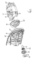
- FIG. 1 shows a generally designated by the reference numeral 2 electric motor driven circular saw, which is designed as a dip circular saw. It comprises a motor housing part 4, which has the electric motor and to which other components such as bow handle 6 and knob handle 8 are attached. Further, the circular saw 2 comprises a gear or statgegephinuseteil 10, of which in the Figures 2 and 3 a motor housing part 4 facing half-shell is shown.
- the gear or statorteil supports a saw shaft 12, rotatably on the clamping flange 14 ( FIG. 2 ), against which a circular saw blade 16 by means of a screw 18 with integrally formed clamping flange 20 is rotatably mounted.
- the gear or statorteil 10 is fastened in a manner to be described in more detail against the motor housing part 4, and the unit thus formed is pivotable relative to a parallel to the saw shaft 12 axis of rotation 22 relative to a base portion 24 of the circular saw 2 for performing dive cuts, in the direction of Double arrow 26.
- a side stop means 28 is shown.
- a circular saw blade 16 extending and releasing protective hood is designated by reference numeral 30.
- the guard 30 is biased in the closing direction (arrow 32) and can be pivoted against the closing direction in the execution of a saw cut automatically in a saw blade increasingly releasing position.
- the motor housing part 4 is cup-shaped and carries on its side facing away from the gear or statgegephasephaseuseteil 10 side a fan 34. He is on his the gear or statgegephasephaseuseteil 10th facing side of a cover part 36 closed, which forms a Heilleitemia.
- the cover part 36 is exemplarily recessed in the region of threaded openings 38 in the cup-shaped part. Both parts are preferably made of sprayable plastic. How very good FIG.
- FIG. 2 a scribed structure 42, which support the stability of the gear or shegegephins, especially in areas where bearing elements, not shown, are arranged, especially with regard to their dimensional accuracy and torsional rigidity in operation.
- a first damping element 42 (FIG. FIG. 3 ) and between the saw shaft 12 and clamping flange 14 for the circular saw blade 16, a second damping element 44 is provided.
- Both damping elements 42, 44 are made of a resiliently deformable material of the type described above.
- the first damping element 42 acts like an annular closed flat gasket.
- the second damping element 44 is formed circular disk-shaped. It would also be conceivable that it has approximately the surface of the clamping flange 14 and is arranged between circular saw blade 16 and clamping flange 14.
- the first damping element 42 is between an end face 46, facing the motor housing part 4, of the block-like housing region 40 of the gear or saw housing part 10 and an end face 48 facing it the lid part 36 is arranged.
- screws not shown are used, which are passed from an inner side of the block-like portion 40 through openings 50 in the first damping element 42 and screwed into said threaded openings 38 in the motor housing part 4.
- a preferably uniform compressive force is exerted on the first damping element 42, and it is thereby compressed in the region of the mutually abutting end faces 46 and 48. Nevertheless, it can develop its dampening effect.
Landscapes
- Engineering & Computer Science (AREA)
- Mechanical Engineering (AREA)
- Sawing (AREA)
Applications Claiming Priority (1)
| Application Number | Priority Date | Filing Date | Title |
|---|---|---|---|
| DE200910036797 DE102009036797A1 (de) | 2009-08-08 | 2009-08-08 | Motorisch angetriebene Handkreissäge |
Publications (2)
| Publication Number | Publication Date |
|---|---|
| EP2281651A2 true EP2281651A2 (fr) | 2011-02-09 |
| EP2281651A3 EP2281651A3 (fr) | 2017-01-18 |
Family
ID=43063367
Family Applications (1)
| Application Number | Title | Priority Date | Filing Date |
|---|---|---|---|
| EP10007607.4A Withdrawn EP2281651A3 (fr) | 2009-08-08 | 2010-07-22 | Scie circulaire manuelle entraînée de manière motorisée |
Country Status (2)
| Country | Link |
|---|---|
| EP (1) | EP2281651A3 (fr) |
| DE (1) | DE102009036797A1 (fr) |
Cited By (2)
| Publication number | Priority date | Publication date | Assignee | Title |
|---|---|---|---|---|
| CN106457594A (zh) * | 2013-12-30 | 2017-02-22 | 罗伯特·博世有限公司 | 用于电动工具的气流管理系统 |
| CN109202172A (zh) * | 2017-06-30 | 2019-01-15 | 苏州宝时得电动工具有限公司 | 便携式电圆锯 |
Family Cites Families (3)
| Publication number | Priority date | Publication date | Assignee | Title |
|---|---|---|---|---|
| GB974674A (en) * | 1962-03-26 | 1964-11-11 | John James Dunce | Improvements in or relating to portable electric power saw tools |
| ITVI20040157A1 (it) * | 2004-06-29 | 2004-09-29 | Positec Group Ltd | Elettroutensile con impugnatura ergonomica ed utensile rotativo |
| DE102007055650B3 (de) * | 2007-11-21 | 2009-04-16 | Metabowerke Gmbh | Motorisch angetriebene Handkreissäge mit verdrehbarer Schutzhaube |
-
2009
- 2009-08-08 DE DE200910036797 patent/DE102009036797A1/de not_active Ceased
-
2010
- 2010-07-22 EP EP10007607.4A patent/EP2281651A3/fr not_active Withdrawn
Non-Patent Citations (1)
| Title |
|---|
| None |
Cited By (4)
| Publication number | Priority date | Publication date | Assignee | Title |
|---|---|---|---|---|
| CN106457594A (zh) * | 2013-12-30 | 2017-02-22 | 罗伯特·博世有限公司 | 用于电动工具的气流管理系统 |
| EP3099455A4 (fr) * | 2013-12-30 | 2017-08-02 | Robert Bosch GmbH | Système de gestion de flux d'air pour un outil électrique |
| US10245663B2 (en) | 2013-12-30 | 2019-04-02 | Robert Bosch Tool Corporation | Airflow management system for a power tool |
| CN109202172A (zh) * | 2017-06-30 | 2019-01-15 | 苏州宝时得电动工具有限公司 | 便携式电圆锯 |
Also Published As
| Publication number | Publication date |
|---|---|
| DE102009036797A1 (de) | 2011-02-10 |
| EP2281651A3 (fr) | 2017-01-18 |
Similar Documents
| Publication | Publication Date | Title |
|---|---|---|
| EP2832497B1 (fr) | Appareil de travail portatif | |
| DE102005016558B4 (de) | Elektrowerkzeug mit Schwingungsdämpfer, Getriebeeinheit | |
| DE102022105334B4 (de) | Elektrischer Kompressor mit einer schalldämmenden Abdeckung | |
| DE102019104639A1 (de) | Kraftwerkzeug | |
| DE202012104105U1 (de) | Elektrowerkzeug einschliesslich eines Antivibrationsgriffes | |
| DE202015101302U1 (de) | Reinigungsgerät in Form eines Staubsaugers oder Vorsatzgerätes für einen Staubsauger | |
| EP2510861B1 (fr) | Agencement de moteur pour un appareil ménager entraîné par moteur électrique | |
| DE102019115263B4 (de) | Lagerungseinrichtung zum Lagern eines Kältemittelverdichters für einen Kraftwagen sowie Lagerungsanordnung | |
| EP2281651A2 (fr) | Scie circulaire manuelle entraînée de manière motorisée | |
| DE3838141A1 (de) | Membranpumpe | |
| DE102005016628B4 (de) | Handgeführter Freischneider | |
| EP3116106A1 (fr) | Machine électrique avec insonorisation | |
| EP1862266B1 (fr) | Machine-outil manuelle à percussion dotée d'une sonnette se déplaçant axialement | |
| DE102011008339A1 (de) | Einrichtung zum Tilgen von Schwingungen an einem Fahrzeugteil | |
| EP1617085B1 (fr) | Ventilateur amorti | |
| WO2023161076A1 (fr) | Tournevis a impact | |
| DE102016216292B4 (de) | Schwingungsentkoppelte und schallreduzierte Aufhängung eines Motors in einem Staubsauger | |
| EP0680669A1 (fr) | Moteur electrique pour equipements auxiliaires montes dans des automobiles. | |
| EP1752259A1 (fr) | Outil électrique | |
| DE102009004748A1 (de) | Geräuscharme Rotorkammer für eine Zentrifuge | |
| EP3725443B1 (fr) | Mécanismes d'amortissement de vibrations pour scies circulaires | |
| DE102008016207B3 (de) | Motorisch angetriebene handgeführte Stichsäge | |
| DE102012108448B4 (de) | Elektromotor | |
| DE102022108918A1 (de) | Elektrisches arbeitsgerät und herstellungsverfahren desselben | |
| DE102005025707B4 (de) | Haubenanordnung eines handgeführten Arbeitsgerätes |
Legal Events
| Date | Code | Title | Description |
|---|---|---|---|
| PUAI | Public reference made under article 153(3) epc to a published international application that has entered the european phase |
Free format text: ORIGINAL CODE: 0009012 |
|
| AK | Designated contracting states |
Kind code of ref document: A2 Designated state(s): AL AT BE BG CH CY CZ DE DK EE ES FI FR GB GR HR HU IE IS IT LI LT LU LV MC MK MT NL NO PL PT RO SE SI SK SM TR |
|
| AX | Request for extension of the european patent |
Extension state: BA ME RS |
|
| PUAL | Search report despatched |
Free format text: ORIGINAL CODE: 0009013 |
|
| AK | Designated contracting states |
Kind code of ref document: A3 Designated state(s): AL AT BE BG CH CY CZ DE DK EE ES FI FR GB GR HR HU IE IS IT LI LT LU LV MC MK MT NL NO PL PT RO SE SI SK SM TR |
|
| AX | Request for extension of the european patent |
Extension state: BA ME RS |
|
| RIC1 | Information provided on ipc code assigned before grant |
Ipc: B23D 47/00 20060101AFI20161209BHEP |
|
| STAA | Information on the status of an ep patent application or granted ep patent |
Free format text: STATUS: THE APPLICATION IS DEEMED TO BE WITHDRAWN |
|
| 18D | Application deemed to be withdrawn |
Effective date: 20170719 |