EP2281666B1 - Méthode et appareil pour simuler la mesure d'un objet et optimisation de la mesure réelle correspondante - Google Patents
Méthode et appareil pour simuler la mesure d'un objet et optimisation de la mesure réelle correspondante Download PDFInfo
- Publication number
- EP2281666B1 EP2281666B1 EP10006149.8A EP10006149A EP2281666B1 EP 2281666 B1 EP2281666 B1 EP 2281666B1 EP 10006149 A EP10006149 A EP 10006149A EP 2281666 B1 EP2281666 B1 EP 2281666B1
- Authority
- EP
- European Patent Office
- Prior art keywords
- detection device
- virtual
- feature
- measuring
- model
- Prior art date
- Legal status (The legal status is an assumption and is not a legal conclusion. Google has not performed a legal analysis and makes no representation as to the accuracy of the status listed.)
- Active
Links
Images
Classifications
-
- G—PHYSICS
- G01—MEASURING; TESTING
- G01B—MEASURING LENGTH, THICKNESS OR SIMILAR LINEAR DIMENSIONS; MEASURING ANGLES; MEASURING AREAS; MEASURING IRREGULARITIES OF SURFACES OR CONTOURS
- G01B11/00—Measuring arrangements characterised by the use of optical techniques
- G01B11/24—Measuring arrangements characterised by the use of optical techniques for measuring contours or curvatures
- G01B11/25—Measuring arrangements characterised by the use of optical techniques for measuring contours or curvatures by projecting a pattern, e.g. one or more lines, moiré fringes on the object
Definitions
- the present invention relates to a method and a device for measuring a feature of a component by means of a, in particular manipulator-guided, detection device.
- optical measuring systems are used, in which a laser projects an optical pattern onto the component, which is recorded by a camera. By evaluating the camera image, the distance, orientation and dimensions of the feature can be determined.
- the EP 1 524 492 B1 describes such a three-dimensional component measurement by means of a robot-guided projector-detector unit.
- the DE 20 2006 020 299 U1 proposes to provide several different types of 3D sensors and to select the appropriate one. From the DE 10 2005 048 136 A1 It is known to move a virtual TCP of a robot-guided light-section sensor by moving the robot into a measuring point of a reference feature.
- EP 1 026 637 A2 discloses apparatus and methods for simulating a vision-based inspection system that measures features of manufacturing objects. It uses graphic models of the objects to be measured in a virtual world and models for describing the lens effects of the camera.
- EP 1 881 383 A2 discloses a simulation device for a robot system-based surveying system with a camera to enable determination of the proper position of the camera and adaptation of further detection parameters and later transferred to the surveying system.
- the EP 1 527 850 A2 discloses a simulation system for a robotic system based camera system to off-line identify the optimal position of the camera and to allow the adaptation of further detection parameters.
- the US 6,249,285 B1 discloses a method and apparatus for configuring a camera-based surveying device. The procedure is performed iteratively until the operator, in his estimation, has received a reliable estimate of the measurement performance.
- the object of the present invention is to improve the measurement of a feature of a component.
- the inventively improved measuring of a feature of a component may, for example, the detection of the position, i.
- the detection device may comprise one or more transmitters, in particular transmitters for emitting electromagnetic radiation such as visible or invisible, in particular ultraviolet, light, X-ray or radio waves, as used in radar technology. Additionally or alternatively, one or more transmitters for emitting sound, in particular ultrasound, may be provided. Accordingly, the detection device may have one or more receivers, in particular for receiving such electromagnetic radiation, for example in the form of one or more CCD or CMOS cameras or optical position sensors ("Position Sensitive Detector", PSD) or for receiving sound.
- transmitters in particular transmitters for emitting electromagnetic radiation such as visible or invisible, in particular ultraviolet, light, X-ray or radio waves, as used in radar technology.
- one or more transmitters for emitting sound, in particular ultrasound may be provided.
- the detection device may have one or more receivers, in particular for receiving such electromagnetic radiation, for example in the form of one or more CCD or CMOS cameras or optical position sensors ("Position Sensitive Detector", PSD) or for receiving sound.
- PSD
- one or more transmitters project a pattern, for example a dot, a dash, a rectangle, another geometric figure or the like onto the feature, such as by a laser irradiating a corresponding optical pattern by means of deflection, apertures or the like.
- One or more receivers take an image in which an image evaluation, in particular an image recognition, detects the reflected or complementary pattern and determines from the image of the pattern, for example position, shape, dimensions, deviation of the feature from a reference configuration or the like.
- a triangulation in particular a light-line or light-section triangulation can be used.
- a scan in which, for example, one or more points, preferably a three-dimensional point cloud, are projected onto the feature or the scanning of the feature by means of radar beams, sound waves or the like can be used to measure the feature.
- the configuration of the detection device and the constellation between detection device and component or feature are referred to as the measurement situation.
- the setting up of the measurement situation may in particular comprise the setting up of the detection device, the component and / or the measurement environment, for example the ambient brightness or illumination.
- the setting-up may in particular comprise a positioning of the detection device and / or the feature relative to each other.
- the component, transmitter and / or receiver can each be stationary or movable, in particular manipulator-guided.
- a transmitter can be arranged on a member, in particular the tool flange, of a manipulator and brought into a predetermined position, defined for example by Cartesian coordinates in an environment-or manipulator-fixed reference system, and / or predetermined orientation, for example can be described by EULER or KARDAN angles relative to the reference system.
- a stationary receiver may then be aligned, for example shifted and / or rotated, to detect the pattern projected by the transmitter and reflected by the feature.
- a receiver can be arranged on a member of the manipulator and be brought by this in a predetermined position to record a pattern from the transmitter to the Characteristic is projected and reflected by this at least partially.
- the stationary or movable, in particular manipulator-guided detection device comprises both at least one transmitter and at least one receiver, for example in the form of a laser, radar or transducer and a corresponding detector, such as in the form of a camera, which together relative to the Feature positioned and optionally shifted from each other and / or can be rotated.
- the setting up of the detection device can then comprise the positioning of the detection device, for example attached to a member, in particular a tool flange, of a manipulator, relative to the feature and / or the displacement of transmitter and receiver relative to one another.
- the setup may also include the specification of measurement parameters of the detection device.
- Measurement parameters may include, for example, the projected pattern, in particular its shape, size and / or orientation, the type, intensity, frequency and / or power of the radiation, the type, accuracy or method of image analysis or the like.
- the virtual model of the detection device preferably describes one or more, preferably all, properties essential for the measurement, or functions of the detection device. For example, it may geometric dimensions of the detection device, EinrichtMH, in particular positioning possibilities, axes of transmitter and / or receiver, such as optical axes of a laser or a camera, and / or other radiation variables such as foci, image planes, apertures, apertures, distortions or the like in dependence describe a position and / or measurement parameters.
- the virtual model of the detection device is automatically adjusted with the real detection device, for example, by transmitting settings made at one of the virtual and the real detection device to the other of the virtual and the real detection device.
- the virtual model of the feature preferably describes one or more, preferably all properties of the feature that are essential for the measurement.
- it may again be geometrical dimensions of the Feature, its structure, surface properties such as its color, and in particular radiation parameters such as reflection properties, such as reflectance and / or absorption levels, refractive indices, polarization or the like describe.
- a virtual model can be created manually or automatically, for example, selected from a catalog of predefined models.
- the virtual model of the detection device or of the feature used is automatically specified as a function of the detection device or the feature to be measured.
- a virtual survey accordingly simulates the measurement of the (virtual) feature by the (virtual) detection device.
- the virtual surveying may comprise a simulated image acquisition of an image, captured by the virtual capture device, of a pattern reflected by the virtual feature.
- the virtual, i.e., virtual, detection is detected by the virtual detector.
- simulated signal for example, a virtual image of a pattern
- a signal processing used in the actual or real detection device for example, an image processing processed.
- the real signal processing is usually already available, which reduces the, in particular software technical, effort for the virtual survey.
- disturbing influences on the measuring process can be taken into account in virtual surveying.
- disturbing extraneous light, reflections on the component or other surfaces, other components, component features or environmental elements such as manipulator elements that obscure the feature or impede positioning of the detection device, color errors, spherical errors, field curvature, distortion, damage or contamination of detection device and / or Component feature, and the like, are simulated in the test virtual surveying.
- the virtual surveying it is then possible to set up the measurement situation, in particular the detection device, and / or to measure the feature. For example, position and / or measurement parameters that have been checked in the simulation, manual or automatically for the real detection device can be adopted. In particular, measuring paths for the manipulator can thus be generated or planned in the case of manipulator-guided detection devices.
- the simulation is used to check predetermined parameters for the detection device and / or the measuring process, for example a manually planned measuring process with predetermined boundary conditions, as may be present in stationary detection devices.
- predetermined parameters for the detection device and / or the measuring process for example a manually planned measuring process with predetermined boundary conditions, as may be present in stationary detection devices.
- different positions and / or measurement parameters for the detection device and / or various other parameters for example ambient lighting conditions and the like, are varied for the measuring process, in each case a virtual measurement is carried out and evaluated, such as in the form of a quality function, in order to optimize the survey, preferably offline in advance.
- a virtual model of the detection device is set up and tested with it virtually, i.e. simulates a virtual model of the feature measured. This can be done during the actual setup of the real measurement situation and / or the actual measurement of the real feature. In a preferred embodiment, it is performed offline in advance as part of a simulation.
- the detection device can be positioned manipulator-controlled.
- the component can be positioned manipulator guided.
- the simulation detection device and / or component model can be positioned in a virtual environment, for example, both the optimal pose of a detection device carrying manipulator, in particular an industrial robot, as well as the optimal measurement position of the component, such as on a Turntable to be determined.
- the setting up of the measurement situation may include the selection or presetting of the position of the detection device and the component to be measured relative to one another.
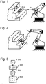
- Fig. 1, 2 show a six-axis industrial robot 4, which carries on its tool flange a detection device in the form of a transmitter-receiver head 1 with a laser and a CCD camera.
- the laser emits a light curtain fanned out by a corresponding optical system in order to project various optical patterns 3 onto a surface, in the exemplary embodiment, for example, a rectangle with an inscribed center cross (cf. Fig. 2 ).
- a feature in the form of a paragraph 2.1 of a step-shaped component 2 is to be measured.
- Fig. 1 shows as a starting situation an unfavorable measurement situation between the stationary component 2, whose position is predetermined relative to the robot base, and the detection device 1. It can be seen that the optical pattern 3 is not optimal to measure the paragraph 2.1, since the dot-dash line indicated laser beam in Essentially parallel to paragraph 2.1, the central cross is at the height of the heel and paragraph 2.1 is thus not illuminated.
- Fig. 3 shows the sequence of a method according to the invention.
- a virtual measurement situation is set up, ie the real measurement situation explained above is mapped in a virtual environment.
- a virtual model 1 'of the detection device 1 is set up, which is the essential one Functions of the transmitter-receiver head 1 describes, for example, the pattern 3 'emitted by it as a function of its position relative to the projection surface.
- a virtual model 2.1 'of the feature 2.1 of the component 2 is set up correspondingly, which maps its essential properties, such as the reflection of a radiated pattern.
- the virtual models can be selected by the user from a model library and configured accordingly.
- the positions can be specified, which corresponds to a zero or reference pose of the robot 4.
- the feature model 2.1 ' is virtually measured with the detection device model 1'.
- the image of the pattern 3 ' is simulated, which the camera in the virtual measurement situation, i. Position of detection device and component model 1 ', 2' to each other, virtually emitted pattern 3 ', etc. receives. This image is evaluated with the image evaluation software also used in the real measuring process (step S30).
- the result of the image evaluation is evaluated with a quality function, which takes into account, for example, whether and how much of the feature 2.1 'to be measured is covered with the pattern 3', which portion of the laser beam is reflected back into the CCD camera, as well as the detected geometry of the virtual feature matches its model parameters or the like.
- a mixed quality criterion is evaluated as a, preferably weighted, sum of a plurality of individual criteria.
- the measurement situation is varied, for example, by arranging the virtual transmitter-receiver head 1 'in a different position relative to the component model 2' and / or varying the emitted pattern 3 ', for example by enlarging it.
- parameters of the measuring process in particular the position of the detection device model 1 'and the size of the virtual optical pattern 3', are changed by an optimizer until the quality function indicates a sufficiently good, then optimally defined measurement situation.
- the influence of the ambient brightness is taken into account by taking this into account in the determination of the simulated image of the pattern 3 ', which virtually captures the camera in the virtual measurement situation.
- an optimal ambient brightness can be determined or the pattern 3 'to be radiated, in particular its shape, size or the laser power, can be adapted to the ambient conditions.
- the type of detection device can be varied. For example, it is possible to switch to a virtual ultrasound transmitter-receiver head if it is determined that an optical measurement is not feasible due to the unchangeable ambient brightness.
- the optimum parameters thus found, in particular the position and laser power of the optimal virtual detection device 1 '* and the optimal optical pattern 3' *, are transmitted to a controller of the robot 4, which for measuring the real component 2 in Fig. 2 Establishes optimal measurement situation shown by the transmitter-receiver head 1 'in a position in which this irradiated the paragraph 2.1 with a suitably large and high-contrast pattern 3.
Landscapes
- Engineering & Computer Science (AREA)
- Computer Vision & Pattern Recognition (AREA)
- Physics & Mathematics (AREA)
- General Physics & Mathematics (AREA)
- Manipulator (AREA)
- Length Measuring Devices By Optical Means (AREA)
Claims (14)
- Procédé de mesure d'une caractéristique (2.1) d'un composant (2), avec les étapes de :a) mise en place d'une situation de mesure avec un équipement de détection (1) et le composant (2) ;b) mesure de la caractéristique (2.1) avec l'équipement de détection ;c) mise en place (S10, S20) d'une situation de mesure virtuelle avec un modèle virtuel (1') de l'équipement de détection (1) et un modèle virtuel (2.1') de la caractéristique (2.1) ; etd) mesure virtuelle (S30) du modèle de caractéristique (2.1') avec le modèle d'équipement de détection (1'),caractérisé en ce que la mesure virtuelle comprend une prise d'image virtuelle (S30) d'une image reflétée par la caractéristique virtuelle (2.1') et détectée par l'équipement de détection virtuel (1') d'un motif (3') reflété par la caractéristique virtuelle (2.1'), dans lequel le motif reflété (3') est appliqué virtuellement par au moins un émetteur sur la caractéristique virtuelle (2.1').
- Procédé selon l'une quelconque des revendications précédentes, caractérisé
en ce que la mise en place de la situation de mesure et/ou la mesure de la caractéristique (2.1) se fait sur la base de la mesure virtuelle. - Procédé selon l'une quelconque des revendications précédentes, caractérisé en ce que la mise en place comprend un positionnement de l'équipement de détection (1) et de la caractéristique (2.1) l'un par rapport à l'autre ou du modèle d'équipement de détection (1') et du modèle virtuel (2.1') de la caractéristique (2.1) l'un par rapport à l'autre.
- Procédé selon l'une quelconque des revendications précédentes, caractérisé en ce que la mise en place comprend la prescription de paramètres de mesure de l'équipement de détection (1) ou du modèle d'équipement de détection (1').
- Procédé selon l'une quelconque des revendications précédentes, caractérisé en ce que les étapes c) et/ou d) sont répétées, les paramètres du processus de mesure, en particulier une position et/ou des paramètres de mesure du modèle d'équipement de détection sont modifiés, en particulier optimisés (S40).
- Procédé selon l'une quelconque des revendications précédentes, caractérisé en ce que l'équipement de détection (1) ou le modèle d'équipement de détection (1') présente au moins un émetteur, en particulier pour l'émission de rayonnement électromagnétique, de préférence de lumière ou d'ondes radio, et/ou de son.
- Procédé selon l'une quelconque des revendications précédentes, caractérisé en ce que l'équipement de détection (1) ou le modèle d'équipement de détection (1') présente au moins un récepteur, en particulier pour la réception de rayonnement électromagnétique, de préférence de lumière ou d'ondes radio, et/ou de son.
- Procédé selon l'une quelconque des revendications précédentes, caractérisé en ce que la mesure ou la mesure virtuelle comprend une évaluation d'image.
- Procédé selon l'une quelconque des revendications précédentes, caractérisé en ce que le modèle de caractéristique virtuel (2,1') décrit des propriétés de surface de la caractéristique (2.1), en particulier la couleur, la structure et/ou la réflectance.
- Procédé selon l'une quelconque des revendications précédentes, caractérisé en ce que la mesure virtuelle tient compte d'interférences, en particulier la lumière externe, les réflexions, d'autres composants ou caractéristiques de composant.
- Procédé selon l'une quelconque des revendications précédentes, caractérisé en ce que l'équipement de détection (1), le modèle d'équipement de détection virtuel (1'), le composant à mesurer (2) et/ou le modèle de composant virtuel (2') sont positionnés automatiquement, en particulier guidés par manipulateur.
- Dispositif de mesure d'une caractéristique (2.1) d'un composant (2) au moyen d'un équipement de détection (1) appartenant au dispositif, en particulier guidé par manipulateur,
caractérisé par
un équipement de simulation, qui est aménagé pour la réalisation d'un procédé selon l'une quelconque des revendications précédentes. - Programme informatique, qui réalise un procédé selon l'une quelconque des revendications 1 à 11, lorsqu'il se déroule dans un équipement de simulation selon la revendication 12.
- Produit programme informatique avec code de programme, qui est enregistré sur un support lisible par machine et comprend un programme informatique selon la revendication 13.
Applications Claiming Priority (1)
| Application Number | Priority Date | Filing Date | Title |
|---|---|---|---|
| DE102009034244A DE102009034244A1 (de) | 2009-07-22 | 2009-07-22 | Verfahren und Vorrichtung zur Vermessung eines Bauteils |
Publications (2)
| Publication Number | Publication Date |
|---|---|
| EP2281666A1 EP2281666A1 (fr) | 2011-02-09 |
| EP2281666B1 true EP2281666B1 (fr) | 2018-01-17 |
Family
ID=42813050
Family Applications (1)
| Application Number | Title | Priority Date | Filing Date |
|---|---|---|---|
| EP10006149.8A Active EP2281666B1 (fr) | 2009-07-22 | 2010-06-14 | Méthode et appareil pour simuler la mesure d'un objet et optimisation de la mesure réelle correspondante |
Country Status (3)
| Country | Link |
|---|---|
| EP (1) | EP2281666B1 (fr) |
| DE (1) | DE102009034244A1 (fr) |
| ES (1) | ES2663537T3 (fr) |
Cited By (1)
| Publication number | Priority date | Publication date | Assignee | Title |
|---|---|---|---|---|
| US11047669B2 (en) | 2018-03-05 | 2021-06-29 | Carl Zeiss Industrielle Messtechnik Gmbh | Method and arrangement for increasing a throughput in workpiece measurement |
Families Citing this family (7)
| Publication number | Priority date | Publication date | Assignee | Title |
|---|---|---|---|---|
| DE102011014299A1 (de) * | 2011-03-17 | 2012-09-20 | Kuka Roboter Gmbh | Verfahren und Mittel zum Steuern einer Automatisierungseinrichtung, insbesodere eines Roboters |
| DE102013209770B4 (de) * | 2013-05-27 | 2015-02-05 | Carl Zeiss Industrielle Messtechnik Gmbh | Verfahren zur Bestimmung von einstellbaren Parametern mehrerer Koordinatenmessgeräte sowie Verfahren und Vorrichtung zur Erzeugung mindestens eines virtuellen Abbilds eines Messobjekts |
| EP3071928B1 (fr) * | 2014-01-20 | 2017-09-06 | Carl Zeiss Industrielle Messtechnik GmbH | Simulation d'enregistrement d'image dans un dispositif de mesure de coordonnées |
| CN110455802B (zh) * | 2019-08-27 | 2023-05-12 | 江苏金恒信息科技股份有限公司 | 基于视觉识别的合金分析装置及方法 |
| DE102019123045B4 (de) | 2019-08-28 | 2022-01-27 | Daniel Futterer | Dummy-Vorrichtung und deren Verwendungen sowie Automatisierungssystem |
| DE102023136547A1 (de) * | 2023-12-22 | 2025-06-26 | Fraunhofer-Gesellschaft zur Förderung der angewandten Forschung eingetragener Verein | Verfahren zur Vermessung oder Inspektion spiegelnder Oberflächen mittels Deflektometrie |
| CN119644930B (zh) * | 2024-11-07 | 2026-01-13 | 赛力斯汽车有限公司 | 一种零件装配误差确定方法、装置、电子设备和存储介质 |
Family Cites Families (12)
| Publication number | Priority date | Publication date | Assignee | Title |
|---|---|---|---|---|
| JP3349652B2 (ja) * | 1997-07-16 | 2002-11-25 | 本田技研工業株式会社 | オフラインティーチング方法 |
| US6249285B1 (en) * | 1998-04-06 | 2001-06-19 | Synapix, Inc. | Computer assisted mark-up and parameterization for scene analysis |
| US7092860B1 (en) * | 1999-02-03 | 2006-08-15 | Mitutoyo Corporation | Hardware simulation systems and methods for vision inspection systems |
| DE50101308D1 (de) * | 2000-03-29 | 2004-02-19 | Tms Produktionssysteme Gmbh Li | Weitgehend selbsttätige Kalibrierung eines Betätigungsarmes eines Roboters |
| JP3892838B2 (ja) | 2003-10-16 | 2007-03-14 | ファナック株式会社 | 3次元測定装置 |
| JP3732494B2 (ja) * | 2003-10-31 | 2006-01-05 | ファナック株式会社 | シミュレーション装置 |
| DE10351669B4 (de) * | 2003-11-05 | 2012-09-13 | Kuka Laboratories Gmbh | Verfahren und Vorrichtung zum Steuern eines Handhabungsgeräts relativ zu einem Objekt |
| DE102004026814A1 (de) * | 2004-06-02 | 2005-12-29 | Kuka Roboter Gmbh | Verfahren und Vorrichtung zum Verbessern der Positioniergenauigkeit eines Handhabungsgeräts |
| DE102005048136B4 (de) | 2005-10-06 | 2010-01-21 | Kuka Roboter Gmbh | Verfahren zum Bestimmen eines virtuellen Tool-Center-Points |
| JP4153528B2 (ja) * | 2006-03-10 | 2008-09-24 | ファナック株式会社 | ロボットシミュレーションのための装置、プログラム、記録媒体及び方法 |
| DE202006020299U1 (de) | 2006-05-16 | 2008-04-24 | Deutsches Zentrum für Luft- und Raumfahrt e.V. | 3D-Vermessungsanordnung |
| JP2008021092A (ja) * | 2006-07-12 | 2008-01-31 | Fanuc Ltd | ロボットシステムのシミュレーション装置 |
-
2009
- 2009-07-22 DE DE102009034244A patent/DE102009034244A1/de not_active Withdrawn
-
2010
- 2010-06-14 EP EP10006149.8A patent/EP2281666B1/fr active Active
- 2010-06-14 ES ES10006149.8T patent/ES2663537T3/es active Active
Non-Patent Citations (1)
| Title |
|---|
| None * |
Cited By (1)
| Publication number | Priority date | Publication date | Assignee | Title |
|---|---|---|---|---|
| US11047669B2 (en) | 2018-03-05 | 2021-06-29 | Carl Zeiss Industrielle Messtechnik Gmbh | Method and arrangement for increasing a throughput in workpiece measurement |
Also Published As
| Publication number | Publication date |
|---|---|
| ES2663537T3 (es) | 2018-04-13 |
| DE102009034244A1 (de) | 2011-01-27 |
| EP2281666A1 (fr) | 2011-02-09 |
Similar Documents
| Publication | Publication Date | Title |
|---|---|---|
| EP2281666B1 (fr) | Méthode et appareil pour simuler la mesure d'un objet et optimisation de la mesure réelle correspondante | |
| JP7045816B2 (ja) | 検査ステーションに配置された車両の最外寸法を測定するための方法及びシステム | |
| DE102018122627B4 (de) | Messsystem | |
| EP3084347B1 (fr) | Procédé d'exécution et de contrôle d'une étape d'usinage sur une pièce | |
| US9239234B2 (en) | Work system and information processing method | |
| US20210255117A1 (en) | Methods and plants for locating points on complex surfaces | |
| DE112015005095T5 (de) | Menschenorientierter Roboter mit Vorrichtung zur kontaktlosen Messung | |
| US20140081459A1 (en) | Depth mapping vision system with 2d optical pattern for robotic applications | |
| DE102016011801A1 (de) | Verfahren zum Kalibrieren einer Vorrichtung zum Herstellen eines dreidimensionalen Objekts und zum Durchführen des Verfahrens ausgebildete Vorrichtung | |
| US20170016712A1 (en) | Position measurement system | |
| KR20060127174A (ko) | 검사경로의 계획방법 및 검사영역의 결정방법 | |
| US20090063093A1 (en) | Method and apparatus for surveying actual measurement data of a component | |
| DE102009030883A1 (de) | Positionsbestimmungssystem, Positionsbestimmungsverfahren und Verwendung derselben | |
| DE102019103519B4 (de) | Vorrichtung zum Bestimmen von dimensionalen und/oder geometrischen Eigenschaften eines Messobjekts | |
| DE102017212371B4 (de) | Bestimmung einer Marke in einem Datensatz mit mittels zumindest eines Laserscanners erfassten dreidimensionalen Oberflächen-Koordinaten einer Szene | |
| JP2019063954A (ja) | ロボットシステム、キャリブレーション方法及びキャリブレーションプログラム | |
| DE102012112025A1 (de) | Verfahren und Vorrichtungen zur Positionsbestimmung einer Kinematik | |
| CN110433989A (zh) | 一种工件表面喷涂的方法 | |
| CN114322754A (zh) | 用于检查修复或装配操作的方法和系统 | |
| CN114440792A (zh) | 多线激光传感的封闭布局结构、扫描拼接及涂胶扫描方法 | |
| WO2005031647A1 (fr) | Procede et dispositif pour determiner, optiquement et sans contact, la situation tridimensionnelle d'un objet | |
| DE102019217324A1 (de) | Auslenkungsmessvorrichtung | |
| DE102019102927B4 (de) | Verfahren und Vorrichtung zum Bestimmen von dimensionalen und/oder geometrischen Eigenschaften eines Messobjekts | |
| US8937725B2 (en) | Measurement assembly including a metrology system and a pointer that directs the metrology system | |
| DE102005037094B3 (de) | Kalibrierverfahren für einen Sensor zur Abstandsmessung |
Legal Events
| Date | Code | Title | Description |
|---|---|---|---|
| PUAI | Public reference made under article 153(3) epc to a published international application that has entered the european phase |
Free format text: ORIGINAL CODE: 0009012 |
|
| AK | Designated contracting states |
Kind code of ref document: A1 Designated state(s): AL AT BE BG CH CY CZ DE DK EE ES FI FR GB GR HR HU IE IS IT LI LT LU LV MC MK MT NL NO PL PT RO SE SI SK SM TR |
|
| AX | Request for extension of the european patent |
Extension state: BA ME RS |
|
| 17P | Request for examination filed |
Effective date: 20110615 |
|
| REG | Reference to a national code |
Ref country code: DE Ref legal event code: R079 Ref document number: 502010014566 Country of ref document: DE Free format text: PREVIOUS MAIN CLASS: B25J0009160000 Ipc: G01B0011250000 |
|
| RIC1 | Information provided on ipc code assigned before grant |
Ipc: G01B 11/25 20060101AFI20170809BHEP Ipc: B25J 9/16 20060101ALI20170809BHEP Ipc: G05B 19/4069 20060101ALI20170809BHEP |
|
| GRAP | Despatch of communication of intention to grant a patent |
Free format text: ORIGINAL CODE: EPIDOSNIGR1 |
|
| INTG | Intention to grant announced |
Effective date: 20170919 |
|
| GRAJ | Information related to disapproval of communication of intention to grant by the applicant or resumption of examination proceedings by the epo deleted |
Free format text: ORIGINAL CODE: EPIDOSDIGR1 |
|
| GRAR | Information related to intention to grant a patent recorded |
Free format text: ORIGINAL CODE: EPIDOSNIGR71 |
|
| GRAS | Grant fee paid |
Free format text: ORIGINAL CODE: EPIDOSNIGR3 |
|
| GRAA | (expected) grant |
Free format text: ORIGINAL CODE: 0009210 |
|
| INTC | Intention to grant announced (deleted) | ||
| AK | Designated contracting states |
Kind code of ref document: B1 Designated state(s): AL AT BE BG CH CY CZ DE DK EE ES FI FR GB GR HR HU IE IS IT LI LT LU LV MC MK MT NL NO PL PT RO SE SI SK SM TR |
|
| INTG | Intention to grant announced |
Effective date: 20171212 |
|
| REG | Reference to a national code |
Ref country code: GB Ref legal event code: FG4D Free format text: NOT ENGLISH |
|
| REG | Reference to a national code |
Ref country code: CH Ref legal event code: EP |
|
| REG | Reference to a national code |
Ref country code: IE Ref legal event code: FG4D Free format text: LANGUAGE OF EP DOCUMENT: GERMAN |
|
| REG | Reference to a national code |
Ref country code: AT Ref legal event code: REF Ref document number: 964720 Country of ref document: AT Kind code of ref document: T Effective date: 20180215 |
|
| REG | Reference to a national code |
Ref country code: DE Ref legal event code: R096 Ref document number: 502010014566 Country of ref document: DE |
|
| REG | Reference to a national code |
Ref country code: SE Ref legal event code: TRGR |
|
| REG | Reference to a national code |
Ref country code: ES Ref legal event code: FG2A Ref document number: 2663537 Country of ref document: ES Kind code of ref document: T3 Effective date: 20180413 |
|
| REG | Reference to a national code |
Ref country code: ES Ref legal event code: PC2A Owner name: KUKA DEUTSCHLAND GMBH Effective date: 20180427 |
|
| REG | Reference to a national code |
Ref country code: FR Ref legal event code: PLFP Year of fee payment: 9 |
|
| REG | Reference to a national code |
Ref country code: NL Ref legal event code: MP Effective date: 20180117 |
|
| REG | Reference to a national code |
Ref country code: LT Ref legal event code: MG4D |
|
| PG25 | Lapsed in a contracting state [announced via postgrant information from national office to epo] |
Ref country code: NL Free format text: LAPSE BECAUSE OF FAILURE TO SUBMIT A TRANSLATION OF THE DESCRIPTION OR TO PAY THE FEE WITHIN THE PRESCRIBED TIME-LIMIT Effective date: 20180117 |
|
| PG25 | Lapsed in a contracting state [announced via postgrant information from national office to epo] |
Ref country code: HR Free format text: LAPSE BECAUSE OF FAILURE TO SUBMIT A TRANSLATION OF THE DESCRIPTION OR TO PAY THE FEE WITHIN THE PRESCRIBED TIME-LIMIT Effective date: 20180117 Ref country code: LT Free format text: LAPSE BECAUSE OF FAILURE TO SUBMIT A TRANSLATION OF THE DESCRIPTION OR TO PAY THE FEE WITHIN THE PRESCRIBED TIME-LIMIT Effective date: 20180117 Ref country code: FI Free format text: LAPSE BECAUSE OF FAILURE TO SUBMIT A TRANSLATION OF THE DESCRIPTION OR TO PAY THE FEE WITHIN THE PRESCRIBED TIME-LIMIT Effective date: 20180117 Ref country code: CY Free format text: LAPSE BECAUSE OF FAILURE TO SUBMIT A TRANSLATION OF THE DESCRIPTION OR TO PAY THE FEE WITHIN THE PRESCRIBED TIME-LIMIT Effective date: 20180117 Ref country code: NO Free format text: LAPSE BECAUSE OF FAILURE TO SUBMIT A TRANSLATION OF THE DESCRIPTION OR TO PAY THE FEE WITHIN THE PRESCRIBED TIME-LIMIT Effective date: 20180417 |
|
| REG | Reference to a national code |
Ref country code: CH Ref legal event code: PUE Owner name: KUKA DEUTSCHLAND GMBH, DE Free format text: FORMER OWNER: KUKA ROBOTER GMBH, DE |
|
| RAP2 | Party data changed (patent owner data changed or rights of a patent transferred) |
Owner name: KUKA DEUTSCHLAND GMBH |
|
| RAP2 | Party data changed (patent owner data changed or rights of a patent transferred) |
Owner name: KUKA DEUTSCHLAND GMBH |
|
| PG25 | Lapsed in a contracting state [announced via postgrant information from national office to epo] |
Ref country code: LV Free format text: LAPSE BECAUSE OF FAILURE TO SUBMIT A TRANSLATION OF THE DESCRIPTION OR TO PAY THE FEE WITHIN THE PRESCRIBED TIME-LIMIT Effective date: 20180117 Ref country code: IS Free format text: LAPSE BECAUSE OF FAILURE TO SUBMIT A TRANSLATION OF THE DESCRIPTION OR TO PAY THE FEE WITHIN THE PRESCRIBED TIME-LIMIT Effective date: 20180517 Ref country code: BG Free format text: LAPSE BECAUSE OF FAILURE TO SUBMIT A TRANSLATION OF THE DESCRIPTION OR TO PAY THE FEE WITHIN THE PRESCRIBED TIME-LIMIT Effective date: 20180417 Ref country code: PL Free format text: LAPSE BECAUSE OF FAILURE TO SUBMIT A TRANSLATION OF THE DESCRIPTION OR TO PAY THE FEE WITHIN THE PRESCRIBED TIME-LIMIT Effective date: 20180117 Ref country code: GR Free format text: LAPSE BECAUSE OF FAILURE TO SUBMIT A TRANSLATION OF THE DESCRIPTION OR TO PAY THE FEE WITHIN THE PRESCRIBED TIME-LIMIT Effective date: 20180418 |
|
| PG25 | Lapsed in a contracting state [announced via postgrant information from national office to epo] |
Ref country code: MT Free format text: LAPSE BECAUSE OF FAILURE TO SUBMIT A TRANSLATION OF THE DESCRIPTION OR TO PAY THE FEE WITHIN THE PRESCRIBED TIME-LIMIT Effective date: 20180117 |
|
| REG | Reference to a national code |
Ref country code: DE Ref legal event code: R081 Ref document number: 502010014566 Country of ref document: DE Owner name: KUKA DEUTSCHLAND GMBH, DE Free format text: FORMER OWNER: KUKA ROBOTER GMBH, 86165 AUGSBURG, DE |
|
| REG | Reference to a national code |
Ref country code: DE Ref legal event code: R097 Ref document number: 502010014566 Country of ref document: DE |
|
| PG25 | Lapsed in a contracting state [announced via postgrant information from national office to epo] |
Ref country code: EE Free format text: LAPSE BECAUSE OF FAILURE TO SUBMIT A TRANSLATION OF THE DESCRIPTION OR TO PAY THE FEE WITHIN THE PRESCRIBED TIME-LIMIT Effective date: 20180117 Ref country code: AL Free format text: LAPSE BECAUSE OF FAILURE TO SUBMIT A TRANSLATION OF THE DESCRIPTION OR TO PAY THE FEE WITHIN THE PRESCRIBED TIME-LIMIT Effective date: 20180117 Ref country code: RO Free format text: LAPSE BECAUSE OF FAILURE TO SUBMIT A TRANSLATION OF THE DESCRIPTION OR TO PAY THE FEE WITHIN THE PRESCRIBED TIME-LIMIT Effective date: 20180117 |
|
| PLBE | No opposition filed within time limit |
Free format text: ORIGINAL CODE: 0009261 |
|
| STAA | Information on the status of an ep patent application or granted ep patent |
Free format text: STATUS: NO OPPOSITION FILED WITHIN TIME LIMIT |
|
| PG25 | Lapsed in a contracting state [announced via postgrant information from national office to epo] |
Ref country code: SK Free format text: LAPSE BECAUSE OF FAILURE TO SUBMIT A TRANSLATION OF THE DESCRIPTION OR TO PAY THE FEE WITHIN THE PRESCRIBED TIME-LIMIT Effective date: 20180117 Ref country code: SM Free format text: LAPSE BECAUSE OF FAILURE TO SUBMIT A TRANSLATION OF THE DESCRIPTION OR TO PAY THE FEE WITHIN THE PRESCRIBED TIME-LIMIT Effective date: 20180117 Ref country code: DK Free format text: LAPSE BECAUSE OF FAILURE TO SUBMIT A TRANSLATION OF THE DESCRIPTION OR TO PAY THE FEE WITHIN THE PRESCRIBED TIME-LIMIT Effective date: 20180117 Ref country code: CZ Free format text: LAPSE BECAUSE OF FAILURE TO SUBMIT A TRANSLATION OF THE DESCRIPTION OR TO PAY THE FEE WITHIN THE PRESCRIBED TIME-LIMIT Effective date: 20180117 |
|
| 26N | No opposition filed |
Effective date: 20181018 |
|
| PG25 | Lapsed in a contracting state [announced via postgrant information from national office to epo] |
Ref country code: SI Free format text: LAPSE BECAUSE OF FAILURE TO SUBMIT A TRANSLATION OF THE DESCRIPTION OR TO PAY THE FEE WITHIN THE PRESCRIBED TIME-LIMIT Effective date: 20180117 |
|
| REG | Reference to a national code |
Ref country code: BE Ref legal event code: MM Effective date: 20180630 |
|
| REG | Reference to a national code |
Ref country code: IE Ref legal event code: MM4A |
|
| PG25 | Lapsed in a contracting state [announced via postgrant information from national office to epo] |
Ref country code: LU Free format text: LAPSE BECAUSE OF NON-PAYMENT OF DUE FEES Effective date: 20180614 Ref country code: MC Free format text: LAPSE BECAUSE OF FAILURE TO SUBMIT A TRANSLATION OF THE DESCRIPTION OR TO PAY THE FEE WITHIN THE PRESCRIBED TIME-LIMIT Effective date: 20180117 |
|
| PG25 | Lapsed in a contracting state [announced via postgrant information from national office to epo] |
Ref country code: IE Free format text: LAPSE BECAUSE OF NON-PAYMENT OF DUE FEES Effective date: 20180614 |
|
| PG25 | Lapsed in a contracting state [announced via postgrant information from national office to epo] |
Ref country code: BE Free format text: LAPSE BECAUSE OF NON-PAYMENT OF DUE FEES Effective date: 20180630 |
|
| REG | Reference to a national code |
Ref country code: AT Ref legal event code: MM01 Ref document number: 964720 Country of ref document: AT Kind code of ref document: T Effective date: 20180614 |
|
| PG25 | Lapsed in a contracting state [announced via postgrant information from national office to epo] |
Ref country code: AT Free format text: LAPSE BECAUSE OF NON-PAYMENT OF DUE FEES Effective date: 20180614 |
|
| PG25 | Lapsed in a contracting state [announced via postgrant information from national office to epo] |
Ref country code: TR Free format text: LAPSE BECAUSE OF FAILURE TO SUBMIT A TRANSLATION OF THE DESCRIPTION OR TO PAY THE FEE WITHIN THE PRESCRIBED TIME-LIMIT Effective date: 20180117 |
|
| PG25 | Lapsed in a contracting state [announced via postgrant information from national office to epo] |
Ref country code: HU Free format text: LAPSE BECAUSE OF FAILURE TO SUBMIT A TRANSLATION OF THE DESCRIPTION OR TO PAY THE FEE WITHIN THE PRESCRIBED TIME-LIMIT; INVALID AB INITIO Effective date: 20100614 Ref country code: PT Free format text: LAPSE BECAUSE OF FAILURE TO SUBMIT A TRANSLATION OF THE DESCRIPTION OR TO PAY THE FEE WITHIN THE PRESCRIBED TIME-LIMIT Effective date: 20180117 |
|
| PG25 | Lapsed in a contracting state [announced via postgrant information from national office to epo] |
Ref country code: MK Free format text: LAPSE BECAUSE OF NON-PAYMENT OF DUE FEES Effective date: 20180117 |
|
| REG | Reference to a national code |
Ref country code: FR Ref legal event code: PLFP Year of fee payment: 14 |
|
| P01 | Opt-out of the competence of the unified patent court (upc) registered |
Effective date: 20230528 |
|
| PGFP | Annual fee paid to national office [announced via postgrant information from national office to epo] |
Ref country code: GB Payment date: 20240402 Year of fee payment: 15 |
|
| PGFP | Annual fee paid to national office [announced via postgrant information from national office to epo] |
Ref country code: DE Payment date: 20240328 Year of fee payment: 15 |
|
| PGFP | Annual fee paid to national office [announced via postgrant information from national office to epo] |
Ref country code: IT Payment date: 20240513 Year of fee payment: 15 Ref country code: FR Payment date: 20240408 Year of fee payment: 15 |
|
| PGFP | Annual fee paid to national office [announced via postgrant information from national office to epo] |
Ref country code: SE Payment date: 20240410 Year of fee payment: 15 |
|
| PGFP | Annual fee paid to national office [announced via postgrant information from national office to epo] |
Ref country code: CH Payment date: 20240701 Year of fee payment: 15 Ref country code: ES Payment date: 20240704 Year of fee payment: 15 |
|
| REG | Reference to a national code |
Ref country code: DE Ref legal event code: R119 Ref document number: 502010014566 Country of ref document: DE |
|
| REG | Reference to a national code |
Ref country code: CH Ref legal event code: H13 Free format text: ST27 STATUS EVENT CODE: U-0-0-H10-H13 (AS PROVIDED BY THE NATIONAL OFFICE) Effective date: 20260127 |
|
| REG | Reference to a national code |
Ref country code: SE Ref legal event code: EUG |
|
| GBPC | Gb: european patent ceased through non-payment of renewal fee |
Effective date: 20250614 |
|
| PG25 | Lapsed in a contracting state [announced via postgrant information from national office to epo] |
Ref country code: GB Free format text: LAPSE BECAUSE OF NON-PAYMENT OF DUE FEES Effective date: 20250614 |
|
| PG25 | Lapsed in a contracting state [announced via postgrant information from national office to epo] |
Ref country code: DE Free format text: LAPSE BECAUSE OF NON-PAYMENT OF DUE FEES Effective date: 20260101 |
|
| PG25 | Lapsed in a contracting state [announced via postgrant information from national office to epo] |
Ref country code: IT Free format text: LAPSE BECAUSE OF NON-PAYMENT OF DUE FEES Effective date: 20250614 |
|
| PG25 | Lapsed in a contracting state [announced via postgrant information from national office to epo] |
Ref country code: FR Free format text: LAPSE BECAUSE OF NON-PAYMENT OF DUE FEES Effective date: 20250630 |
|
| PG25 | Lapsed in a contracting state [announced via postgrant information from national office to epo] |
Ref country code: CH Free format text: LAPSE BECAUSE OF NON-PAYMENT OF DUE FEES Effective date: 20250630 |