EP2281966B1 - Fenêtre coulissante de toit dotée de plusieurs battants - Google Patents
Fenêtre coulissante de toit dotée de plusieurs battants Download PDFInfo
- Publication number
- EP2281966B1 EP2281966B1 EP10006078.9A EP10006078A EP2281966B1 EP 2281966 B1 EP2281966 B1 EP 2281966B1 EP 10006078 A EP10006078 A EP 10006078A EP 2281966 B1 EP2281966 B1 EP 2281966B1
- Authority
- EP
- European Patent Office
- Prior art keywords
- window
- sash
- roof sliding
- sliding window
- frame
- Prior art date
- Legal status (The legal status is an assumption and is not a legal conclusion. Google has not performed a legal analysis and makes no representation as to the accuracy of the status listed.)
- Active
Links
Images


Classifications
-
- E—FIXED CONSTRUCTIONS
- E04—BUILDING
- E04D—ROOF COVERINGS; SKY-LIGHTS; GUTTERS; ROOF-WORKING TOOLS
- E04D13/00—Special arrangements or devices in connection with roof coverings; Protection against birds; Roof drainage ; Sky-lights
- E04D13/03—Sky-lights; Domes; Ventilating sky-lights
- E04D13/035—Sky-lights; Domes; Ventilating sky-lights characterised by having movable parts
- E04D13/0358—Sky-lights; Domes; Ventilating sky-lights characterised by having movable parts the parts moving, in their own plane, e.g. rolling or sliding, or moving in parallel planes with or without an additional movement, e.g. both pivoting and rolling or sliding
-
- E—FIXED CONSTRUCTIONS
- E05—LOCKS; KEYS; WINDOW OR DOOR FITTINGS; SAFES
- E05D—HINGES OR SUSPENSION DEVICES FOR DOORS, WINDOWS OR WINGS
- E05D15/00—Suspension arrangements for wings
- E05D15/06—Suspension arrangements for wings for wings sliding horizontally more or less in their own plane
- E05D15/12—Suspension arrangements for wings for wings sliding horizontally more or less in their own plane consisting of parts connected at their edges
-
- E—FIXED CONSTRUCTIONS
- E05—LOCKS; KEYS; WINDOW OR DOOR FITTINGS; SAFES
- E05D—HINGES OR SUSPENSION DEVICES FOR DOORS, WINDOWS OR WINGS
- E05D15/00—Suspension arrangements for wings
- E05D15/16—Suspension arrangements for wings for wings sliding vertically more or less in their own plane
- E05D15/24—Suspension arrangements for wings for wings sliding vertically more or less in their own plane consisting of parts connected at their edges
- E05D15/242—Hinge connections between the parts
-
- E—FIXED CONSTRUCTIONS
- E05—LOCKS; KEYS; WINDOW OR DOOR FITTINGS; SAFES
- E05F—DEVICES FOR MOVING WINGS INTO OPEN OR CLOSED POSITION; CHECKS FOR WINGS; WING FITTINGS NOT OTHERWISE PROVIDED FOR, CONCERNED WITH THE FUNCTIONING OF THE WING
- E05F15/00—Power-operated mechanisms for wings
- E05F15/60—Power-operated mechanisms for wings using electrical actuators
- E05F15/603—Power-operated mechanisms for wings using electrical actuators using rotary electromotors
- E05F15/632—Power-operated mechanisms for wings using electrical actuators using rotary electromotors for horizontally-sliding wings
- E05F15/635—Power-operated mechanisms for wings using electrical actuators using rotary electromotors for horizontally-sliding wings operated by push-pull mechanisms, e.g. flexible or rigid rack-and-pinion arrangements
-
- E—FIXED CONSTRUCTIONS
- E05—LOCKS; KEYS; WINDOW OR DOOR FITTINGS; SAFES
- E05F—DEVICES FOR MOVING WINGS INTO OPEN OR CLOSED POSITION; CHECKS FOR WINGS; WING FITTINGS NOT OTHERWISE PROVIDED FOR, CONCERNED WITH THE FUNCTIONING OF THE WING
- E05F15/00—Power-operated mechanisms for wings
- E05F15/60—Power-operated mechanisms for wings using electrical actuators
- E05F15/603—Power-operated mechanisms for wings using electrical actuators using rotary electromotors
- E05F15/632—Power-operated mechanisms for wings using electrical actuators using rotary electromotors for horizontally-sliding wings
- E05F15/643—Power-operated mechanisms for wings using electrical actuators using rotary electromotors for horizontally-sliding wings operated by flexible elongated pulling elements, e.g. belts, chains or cables
-
- E—FIXED CONSTRUCTIONS
- E05—LOCKS; KEYS; WINDOW OR DOOR FITTINGS; SAFES
- E05Y—INDEXING SCHEME ASSOCIATED WITH SUBCLASSES E05D AND E05F, RELATING TO CONSTRUCTION ELEMENTS, ELECTRIC CONTROL, POWER SUPPLY, POWER SIGNAL OR TRANSMISSION, USER INTERFACES, MOUNTING OR COUPLING, DETAILS, ACCESSORIES, AUXILIARY OPERATIONS NOT OTHERWISE PROVIDED FOR, APPLICATION THEREOF
- E05Y2201/00—Constructional elements; Accessories therefor
- E05Y2201/40—Motors; Magnets; Springs; Weights; Accessories therefor
- E05Y2201/47—Springs
- E05Y2201/488—Traction springs
-
- E—FIXED CONSTRUCTIONS
- E05—LOCKS; KEYS; WINDOW OR DOOR FITTINGS; SAFES
- E05Y—INDEXING SCHEME ASSOCIATED WITH SUBCLASSES E05D AND E05F, RELATING TO CONSTRUCTION ELEMENTS, ELECTRIC CONTROL, POWER SUPPLY, POWER SIGNAL OR TRANSMISSION, USER INTERFACES, MOUNTING OR COUPLING, DETAILS, ACCESSORIES, AUXILIARY OPERATIONS NOT OTHERWISE PROVIDED FOR, APPLICATION THEREOF
- E05Y2900/00—Application of doors, windows, wings or fittings thereof
- E05Y2900/10—Application of doors, windows, wings or fittings thereof for buildings or parts thereof
- E05Y2900/13—Type of wing
- E05Y2900/148—Windows
- E05Y2900/152—Roof windows
Definitions
- the invention relates to a roof sliding window with a plurality of window sashes which are displaceable side by side in the window opening in a open position releasing a window opening from one of the window sash stacking Vietnamese sedanvorraum.
- Such roof sliding windows are usually used as roof windows or, for example, as an emergency exit or smoke heat vent or are designed in such a way and allow for a relatively small space requirement closing or releasing a large window opening.
- Such roof sliding windows according to the prior art, for example, in DE19711469A1 . WO91 / 19070A1 and DE9016628U1 disclosed.
- the special feature is that the individual window sashes are stacked when opening or releasing the window opening in the Nachschreibvorraumraumone above the other.
- the space required for stowing the window sash next to the window opening substantially corresponds to the width of one of the window sash.
- the window sashes have connectable coupling means.
- the coupling means are designed such that when a window sash is moved into the window opening, this is coupled to the underlying and nachgurenden by the Nachschreibvorraum window sash. This ensures that only one of the sash must be moved, and this automatically pulls the other, following sash after him. The same applies when opening or releasing the window opening, in which it is sufficient to move one of the window sash in the Nachschreibvorraumiques. Due to the coupling, the window sashes remaining in the window opening follow automatically.
- the above-mentioned device of the Nachschreibvoroplasty serves to adjust the spring tension of the spring element.
- the device is controllable in such a way that a coupling-up does not occur. This means that the spring tension of the spring element by means of the device is reduced such that when moving a sash from the Nachschreibvoroplasty or the underlying casement or the remaining in the Nachschreibvoroplasty / remaining sash does not move, since his or her weight the remaining Spring tension of the spring element exceeds. This prevents a window sash from coming in, and thus the sashes from being interlinked with each other.
- the roof sliding window according to the invention has the advantage that the window sash can be moved independently of each other in the window opening. This facilitates in particular the cleaning of the roof sliding window. Namely, it is now possible for a user, for example, to move a single window sash out of the follower device into the window opening, so that it can clean the window sash in question, in particular from the outside, through the remaining released window opening. In a roof sliding window with, for example, three window sashes, the user can thus, for example, first move the first window sash into the window opening, clean it from the outside, and then only the second sash in order to clean it from the outside. The outside of the third, remaining in the Nachschvorraumcardi window sash can then be cleaned in the Nachschreibvorraumraum.
- the Nachrückvortechnische on a corresponding access opening If necessary, this can be done Also special cleaning tool can be provided.
- the user can either individually during assembly or even later determine which of the casements to be verkuppelt each other, and in which casement a coupling nachzuschiben should be omitted.
- the Nachschvoriques has a height-movable and operatively connected to the spring element frame on which the sash can be stacked.
- the Nachschvorgang the window sash is thus effected by the movable in height frame, which is operatively connected to the prestressed spring element.
- At least the lowermost window sash and the frame advantageously have corresponding guide means for guiding the window sash on the frame.
- the spring element between the frame and a displaceable for adjusting the spring tension holding means of the device is biased. This means that the device can act directly on the spring element, in particular on the spring travel of the spring element and thus on the spring tension.
- the holding means is displaceable by an electric motor.
- the device is remotely controllable, so that the spring tension of the spring element is adjustable from any location, whereby the operation and maintenance or cleaning is simplified.
- the device for displacing the holding means has an electromotive rack drive.
- the electromotive drive unit of the rack drive can be arranged stationary and the rack on which the holding means is arranged to be movable.
- the holding means is arranged on the drive unit, which is movable on the stationary rack.
- the rack is aligned in the longitudinal extent of the spring element, so that the spring travel or the spring tension is easy and precise adjustable.
- the spring element is designed as a tension spring, so that a tensile force is always transmitted from the device, or the holding means, via the spring element to the frame.
- the spring element is designed as a spiral spring. This allows a cost-effective production of the roof sliding window and easy installation.
- the device described above is not only suitable to prevent a coupling nachguren if necessary, but that it is also suitable over the life of the spring element away occurring fatigue of both the spring element as well as other components relating to the process of the frame of the follower. If the device is designed to be remotely controllable, as described above, this allows easy maintenance and readjustment of the roof sliding window, without having to dismantle or partially dismantle the roof sliding window.
- a cable, Zahnriemen- and / or chain hoist between the frame and the spring element is interposed.
- the device for adjusting the spring tension space-optimized in or on the Nachschreibvorraumraum or the roof sliding window are arranged.
- the movable in height frame is tiltable.
- the tilting axis is aligned perpendicular to the direction of displacement of the window sash and advantageously arranged centrally with respect to the frame and / or the window sash.
- the tilting of the frame makes it possible, in particular, for the window sashes to be able to tilt with respect to the displacement plane in the window opening in the follower device, so that the window sash that is moved out of or into the follower device is tilted the underlying inclined / tilted sash off or runs up.
- the Nachschvorraumiques has at least one, the frame overlapping carriage, which is conveniently movable on a stationary frame in height.
- the window sash as a coupling agent in each case have at least one driving element.
- a Driving element here is an element to understand that is designed and arranged on a window sash and / or aligned that it engages a corresponding entrainment of an adjacent - above or below - window sash when moving a window sash form-fitting and thereby entrains the adjacent sash.
- the overhead window sash as entrainment each have a catch rail, in which engages a driving element of an underlying sash when coupling rearward.
- the catching track captures the entrainment of the underlying sash - as long as this moves behind -, whereby the two sash are coupled together.
- the entrainment element of the underlying window sash is designed as a particular rotatably mounted catch roller. Due to the rotatable mounting frictional forces between the window sashes when moving minimized and the sliding of the sash altogether. Conveniently, the catch rail is aligned obliquely, in particular here the rotatable mounting of the roller leads to a reduction in friction force. The inclination also causes the moving of a window sash raised in the Nachschvoriques underlying sash or pushed down - depending on the direction of the shift - thereby supporting the procedure of the framework.
- the catch rail seen in cross-section on a U-profile wherein the roller engages in the catch rail such that it cooperates with two legs of the U-profile, depending on the direction of movement of the sash.
- the roller engages in the catch rail such that it cooperates with two legs of the U-profile, depending on the direction of movement of the sash.
- the U-profile having catching rail causes the window sash lying on the frame of the Nachschvorraumiques is first pressed down in the region of the roller, so preferably on its side facing the window opening, whereby - if the frame is tilted as described above - first the frame is tilted together with the window sash lying on it so far that the following window sash pushed over the now tilted under it sash and then the entire underlying sash or the frame is moved in height.
- each rack is associated with a toothed rack which can be brought into operative connection with an electromotive drive for displacing the casements in the window opening.
- the electromotive Drive designed as a reduction drive and arranged at the window opening associated side of the Nachschreibvorraumiques.
- the roof sliding window has at least one sensor for detecting the position of at least partially pushed out of the Nachschvorraumuite window sash.
- the sensor is operatively connected to the means for adjusting the spring tension, so that the time at which the spring tension for preventing a coupling Vietnamese Wegens should be reduced, is controlled in a simple manner by the sensor / detected.
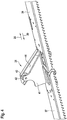
- FIG. 1 shows a perspective view of an embodiment of an advantageous roof sliding window 1, which is particularly suitable for installation in residential roofs.
- a Nachschreibvorraum 2 is shown.
- the Nachschreibvorraumcardi 2 window sash - not shown here - the roof sliding window 1 stacked one above the other and from there side by side slidable in a window opening.
- the Nachschreibvorraumcardi 2 a movable in height frame 3, on which the sash can be stacked.
- FIG. 2 is a schematic side view of the Nachschreibvoruze 2 - seen from the window opening -, depends the frame 3 of the Nachschreibvoruze 2 on both sides of a respective chain hoist 4 and 5.
- the respective chain hoist 4, 5 is on a frame supporting, on a stationary frame 6 of the Nachschreibvoruze 2 guided slide 7 and 8 attached.
- the respective chain hoist 4, 5 leads from the corresponding carriage 7, 8 via a chain wheel 9 or 10 arranged above the frame 3, where the chain hoist is deflected by 180 ° and leads to a further chain wheel 11 or 12 below the frame 3.
- the respective chain hoist 4, 5 is substantially at 90 ° is redirected to a below the frame 3 and in the bottom region of the Nachschreibvortechnik 2 arranged device 13.
- the device 13 has according to FIG. 2 an electric motor rack drive 14, which is operatively connected to the chain hoist 4, and an electric motor rack drive 15, which is operatively connected to the chain hoist 5.
- the rack drives 14 and 15 each have a stationary rack 16 and 17, respectively, on each of which a drive unit 18 or 19 can be moved by an electric motor.
- a holding means 20, 21 is arranged in each case, which may be formed in particular integrally with a housing part of the respective drive unit 18 or 19.
- the holding means 20, 21 are each connected to one end of a spring element 22, 23, whose respective other end is connected to the chain hoist 4 or 5.
- the spring elements 22, 23 are thus interposed between the device 13 and the frame 3. According to the embodiment of the FIG.
- the spring elements 22, 23 each formed as a spiral spring 24 and loaded on train.
- the chain hoists 4, 5 each have two chains running parallel to one another, which are tensioned between an intermediate piece 25 connected to the corresponding end of the respective spring element 22, 23 and the corresponding slide 7, 8.
- the rack drives 14 and 15 of the device 13 not with each other, as in the FIG. 2 for reasons of clarity shown schematically, but are preferably arranged side by side at the same height.
- the drive units 18, 19 are arranged stationary, while the racks 16, 17 corresponding to the holding means 20, 21 and by means of the drive units 18, 19 for adjusting the spring tension can be moved.
- the window sash advantageously have coupling means 31, as they are exemplified in the FIGS. 4 to 6 are shown. On the embodiment and operation of the coupling agent will be discussed in more detail later.
- the frame 3 Due to its weight and / or due to a certain shape of the coupling means 31, the frame 3 is moved downwards, as indicated by an arrow 29, so that the following window sash can be pushed over the window sash 3 lying on the frame. This is repeated until all of the sashes in the follower 2 are stacked one above the other.
- a particular advantage of the roof sliding window is that when moving a sash in the window opening, the device 13 is controlled so that a coupling rearward movement of the remaining window sash is omitted, and from the Nachschreibvorcardi 2 pushed out window sash is moved alone in the window opening without him pulling another window sash after.
- the drive units 18 and 19 on the racks 16 or 17, or alternatively by moving the racks 16, 17 by means of the drive units 18 and 19, the spring tension of the spring elements 22, 23 can be influenced or adjusted in a simple manner. This makes it possible, when moving a sash out of the Nachschreibvoroplasty 2 in the window opening to prevent a coupling nachschreiben.
- the spring tension is reduced while a window sash is moved into the window opening, the spring tension is not sufficient to move the frame 3 with the remaining / remaining window sashes in the direction of arrow 27 upwards. Rather, the window sash remain substantially in the previous position without moving.
- the coupling means 31 can thus not be brought into operation with each other, so that the casement alone or detached from the underlying casement is moved into the window opening or can be.
- the drive 32 is a gear, toothed belt or chain drive, which can be brought into operative connection with the window wings associated racks.
- the drive is in the area close to the window opening, spaced from the frame 3, as in FIG FIG. 3 represented, arranged. This allows the user to move the window sashes individually or continuously in the window opening.
- a clutch is advantageously provided by means of which the drive 32 can be decoupled from the window sashes, so that even in a power failure, for example, the window sash can be moved without the frictional torque of the drive must be overcome.
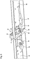
- FIG. 3 is a plan view of the carriage 8, the frame 3 is tiltable about a suitably aligned perpendicular to the direction of movement of the sash axis.
- the FIG. 3 shows on the one hand the frame 3 in a horizontal position in which the frame is parallel or in a plane with the window frame guide 28, so that the lying on the frame 3 sash moved easily and horizontally in or on the frame guide 28 into the window opening can be (for example by means of the electric motor drive 32).
- the shock absorber 33 is correspondingly higher than the shock absorber 34 is formed.
- the shock absorbers 33 and 34 are formed at least partially elastically deformable, so that shocks are damped when tilting the frame 3.
- 7 corresponding shock absorbers are advantageously arranged on the carriage.
- the tilting of the frame 3 allows when moving a sash in or out of the Nachschreibvorraum 2 that the carriage 7, 8 or the frame 3 over the entire travel, so over the entire width of the sash, in height in the direction of arrows 27 or 29, depending on the direction of movement, is moved.
- the frame 3 is advantageously in tilted position (shown in phantom), with its pointing to the frame guide 28 end at the level of the frame guide 28, so that when the first sash is inserted into the Nachschreibvorraum, the frame 3 "slowly" down - in the direction of arrow 29 - is moved.
- the frame 3 can also lie horizontally in the extension of the window frame guide 28 (solid line) when all the window sashes are in the window opening.
- FIGS. 4 to 6 show an embodiment of the above-mentioned coupling means 31 of the window sash of the roof sliding window 1 in different perspective views.
- the FIG. 6 shows for this purpose fittings 35, 36 and 37 of three window wings of the roof sliding window 1.
- the fittings 35, 36 and 37 each have a with the electric motor drive 32 operatively engageable rack 38, 39 and 40 for moving the window sash.
- the fittings 35 to 37 and thus the corresponding associated window sash by means of the coupling means 31 are releasably coupled together.
- the fittings 36 and 37 will now be with reference to the FIGS. 4 and 5 the coupling means 31 will be explained in more detail.
- the fitting 37 has a roller 42 rotatably mounted on a flange 42, whose axis of rotation is aligned perpendicular to the direction of movement of the sash or the fittings 35 to 37.
- the roller 42 in this case forms a driving element 43 of the fitting 37.
- the fitting 36 has at its fitting 37 associated end as entrainment a catch rail 44, which seen in cross section has a U-profile and obliquely, approximately at an angle of 45 ° the fitting 36 is aligned.
- the two legs of the catching rail 44 engage around the roller 42.
- the window sashes are in the window opening, the movement of one of the window sashes or fittings 36, 37 on the other fitting 37, 36 is transmitted via the catching rail 44 and the roller 42.
- the window sash are guided in the window opening, that they are displaceable only in the displacement direction, ie in a plane.
- the frame 3 is tiltably mounted as described above, the lying on the frame 3 sash is tilted accordingly, so that the fitting 36 having window sash over the fitting 37 having window sash can be pushed into the Nachschreibvorraum. Accordingly, it behaves between the fittings 36 and 35. As a result, the casements are stacked one above the other in the Nachschreibvortechnik 2 in a simple manner.
- the catch rail 44 is pushed over the roller 42 when moving a window sash out of the follower 2, so that the driving element 43 of the window sash below (roller 42) not taken.
- the fittings at their ends in each case two mutually perpendicular roller body 45 and 46, which eino in corresponding guides of the window frame guide 28 and thereby support the window sash and lead.
- At least the fitting 36 advantageously has at its catch rail 44 end having a cam contour 47, which is arranged at the bottom spaced from the catch rail 44 such that the roller 42 runs on the cam contour.
- the cam contour 47 causes either the fitting 36 or the fitting 37 and thus the corresponding window sash is tilted so that a bent sheet metal edge of a window sash, which is located on the opposite side of the sash and should prevent the ingress of water between the sashes over the Rolled body 46 is lifted away.
- the advantageous roof sliding window thus provides a simple and inexpensive way to move the sash independently of each other in the window opening, and thus to enable a user in particular to clean the outside of the sash.
Landscapes
- Engineering & Computer Science (AREA)
- Architecture (AREA)
- Civil Engineering (AREA)
- Structural Engineering (AREA)
- Power-Operated Mechanisms For Wings (AREA)
- Wing Frames And Configurations (AREA)
Claims (17)
- Fenêtre de toit coulissante (1) comprenant plusieurs battants de fenêtre qui, dans une position ouverte libérant une ouverture de fenêtre, peuvent être glissés l'un à côté de l'autre dans l'ouverture de fenêtre à partir d'un dispositif de coulissement (2) superposant les battants de fenêtre l'un sur l'autre, dans lequel le dispositif de coulissement (2) présente au moins un élément de ressort (22, 23) précontraint pour un coulissement automatique des battants de fenêtres superposés l'un sur l'autre, et dans lequel les battants de fenêtres présentent des moyens d'accouplement (31) par lesquels un battant de fenêtre peut être couplé de façon séparable lors de son glissement avec un battant de fenêtre coulissant, caractérisée en ce que le dispositif de coulissement (2) présente un dispositif (13) pouvant être commandé de telle façon pour régler la tension de ressort de l'élément de ressort (22, 23) qu'il n'y a pas de coulissement d'accouplement.
- Fenêtre de toit coulissante selon la revendication 1, caractérisée en ce que le dispositif de coulissement (2) présente un châssis (3) réglable en hauteur et lié fonctionnellement avec l'élément de ressort (22, 23), sur lequel les battants de fenêtre sont empilables.
- Fenêtre de toit coulissante selon la revendication 2, caractérisée en ce que l'élément de ressort (22, 23) est précontraint entre le châssis (3) et un moyen de retenue (20, 21) du dispositif (13) pouvant être déplacé pour régler la contrainte du ressort.
- Fenêtre de toit coulissante selon la revendication 3, caractérisée en ce que le moyen de retenue (20, 21) peut être déplacé par un moteur électrique.
- Fenêtre de toit coulissante selon la revendication 3 ou 4, caractérisée en ce que le dispositif (13) présente un entraînement à crémaillère à moteur électrique (14, 15) pour déplacer le moyen de retenue (20, 21).
- Fenêtre de toit coulissante selon l'une des revendications précédentes, caractérisée en ce que l'élément de ressort (22, 23) est conçu en tant que ressort de traction.
- Fenêtre de toit coulissante selon l'une des revendications précédentes, caractérisée en ce que l'élément de ressort (22, 23) est conçu en tant que ressort à boudin (24).
- Fenêtre de toit coulissante selon la revendication 2 ou 3, caractérisé en ce qu'une traction à câble, à courroie dentée et/ou un palan à chaîne (4, 5) est monté(e) en intermédiaire entre le châssis (3) et l'élément de ressort (22, 23).
- Fenêtre de toit coulissante selon l'une des revendications 2, 3 ou 8, caractérisée en ce que le châssis (3) est disposé en étant basculable.
- Fenêtre de toit coulissante selon l'une des revendications 2, 3, 8 ou 9, caractérisée en ce que le dispositif de coulissement (2) présente au moins un chariot (7, 8) supportant le châssis (3).
- Fenêtre de toit coulissante selon l'une des revendications précédentes, caractérisée en ce que les battants de fenêtre présentent respectivement au moins un élément entraîneur (43) en tant que moyen d'accouplement (31).
- Fenêtre de toit coulissante selon la revendication 11, caractérisée en ce que le battant de fenêtre supérieur présente en tant qu'élément entraîneur (43), un rail collecteur (44) dans lequel l'élément entraîneur (43) d'un battant de fenêtre reposant dessous se met en prise lors du coulissement d'accouplement.
- Fenêtre de toit coulissante selon l'une des revendications 11 ou 12, caractérisée en ce que l'élément entraîneur (43) du battant de fenêtre reposant dessous est formé en tant que rouleau (42) disposé rotatif.
- Fenêtre de toit coulissante selon la revendication 12, caractérisée en ce que le rail collecteur (44) présente un profil en U vu en coupe transversale.
- Fenêtre de toit coulissante selon l'une des revendications 12 ou 14, caractérisée en ce que le rail collecteur (44) est aligné de biais dans le sens de mouvement.
- Fenêtre de toit coulissante selon l'une des revendications précédentes, caractérisée en ce que chacun des battants de fenêtre présente une crémaillère (38, 39, 40) qui peut être amenée en liaison fonctionnelle avec un entraînement (32), en particulier à moteur électrique, pour glisser les battants de fenêtre dans l'ouverture de fenêtre.
- Fenêtre de toit coulissante selon l'une des revendications précédentes, caractérisée par un capteur pour détecter la position d'un battant de fenêtre poussé dans l'ouverture de fenêtre.
Applications Claiming Priority (1)
| Application Number | Priority Date | Filing Date | Title |
|---|---|---|---|
| DE102009034205.2A DE102009034205B4 (de) | 2009-07-15 | 2009-07-15 | Dachschiebefenster mit mehreren Fensterflügeln |
Publications (3)
| Publication Number | Publication Date |
|---|---|
| EP2281966A2 EP2281966A2 (fr) | 2011-02-09 |
| EP2281966A3 EP2281966A3 (fr) | 2015-07-15 |
| EP2281966B1 true EP2281966B1 (fr) | 2017-10-11 |
Family
ID=42697509
Family Applications (1)
| Application Number | Title | Priority Date | Filing Date |
|---|---|---|---|
| EP10006078.9A Active EP2281966B1 (fr) | 2009-07-15 | 2010-06-11 | Fenêtre coulissante de toit dotée de plusieurs battants |
Country Status (2)
| Country | Link |
|---|---|
| EP (1) | EP2281966B1 (fr) |
| DE (1) | DE102009034205B4 (fr) |
Families Citing this family (4)
| Publication number | Priority date | Publication date | Assignee | Title |
|---|---|---|---|---|
| CN111188545B (zh) * | 2020-03-13 | 2025-04-22 | 浙江瑞德建筑五金有限公司 | 定位风撑 |
| CN113862747B (zh) * | 2021-09-09 | 2023-09-19 | 广东兴发铝业(河南)有限公司 | 一种铝型材表面氧化膜的镀膜装置 |
| EP4361370A1 (fr) * | 2022-10-28 | 2024-05-01 | Tie Down, Inc. | Dispositif d'actionnement d'une trappe, un système d'accès à la trappe comprenant ce dispositif et une méthode d'utilisation d'un dispositif d'actionnement de trappe |
| US11920397B1 (en) | 2022-10-28 | 2024-03-05 | Tie Down, Inc. | Hatch lift assist device |
Family Cites Families (5)
| Publication number | Priority date | Publication date | Assignee | Title |
|---|---|---|---|---|
| DE2844022C2 (de) * | 1978-10-09 | 1980-11-27 | O & K Orenstein & Koppel Ag, 1000 Berlin | Schiebeplattenvorrichtung zum Schließen einer öffnung |
| GB9011906D0 (en) * | 1990-05-29 | 1990-07-18 | Emanuel Stephen W | Architectural fittings such as windows and doors |
| DE9016628U1 (de) * | 1990-12-07 | 1991-05-02 | Zenker, Karl-Heinz, 7500 Karlsruhe | Bewegliche Abschluß-, Abschirm- und/oder Schutzvorrichtung für Dachbalkone, Terrassenüberdachungen und Dachöffnungen jeder Art (Gleitfenster) |
| DE19711469C2 (de) * | 1997-03-18 | 2002-04-18 | Zenker Karl Heinz | Dachflächenfenster |
| DE10351941A1 (de) * | 2003-11-07 | 2005-06-09 | Karl-Heinz Zenker | Vorrichtung zum Anheben und Absenken von Dachfenstergleitelementen |
-
2009
- 2009-07-15 DE DE102009034205.2A patent/DE102009034205B4/de not_active Expired - Fee Related
-
2010
- 2010-06-11 EP EP10006078.9A patent/EP2281966B1/fr active Active
Non-Patent Citations (1)
| Title |
|---|
| None * |
Also Published As
| Publication number | Publication date |
|---|---|
| DE102009034205A1 (de) | 2011-01-27 |
| DE102009034205B4 (de) | 2014-02-13 |
| EP2281966A2 (fr) | 2011-02-09 |
| EP2281966A3 (fr) | 2015-07-15 |
Similar Documents
| Publication | Publication Date | Title |
|---|---|---|
| EP1886853B1 (fr) | Store de fenêtre doté d'un actionnement par le lève-glace | |
| WO2008125343A1 (fr) | Agencement de façade pliable ou de store pliable et dispositif d'actionnement correspondant | |
| DE20013512U1 (de) | Sektionalhub- oder Falttor | |
| EP1886854A1 (fr) | Store de fenêtre manuel doté d'un retour automatique | |
| WO2016096119A1 (fr) | Meuble, en particulier armoire | |
| DE202012001762U1 (de) | Kettenantrieb für einen Stellantrieb zum automatischen Öffnen und Schließen einer Lüftungsvorrichtung | |
| EP2281966B1 (fr) | Fenêtre coulissante de toit dotée de plusieurs battants | |
| EP2634341A2 (fr) | Porte accordéon avec deux éléments de volet pliant rigides en soi dotés de bords infléchissants et non infléchissants en alternance et dispositif d'actionnement correspondant | |
| DE3710237A1 (de) | Fangvorrichtung fuer nach oben oeffnende tore | |
| DE2507893C3 (de) | Fensterheber für vertikal unterteilte Kraftfahrzeugschiebefenster | |
| EP1639224A2 (fr) | Porte sectionnelle | |
| CH635164A5 (de) | Raffstore. | |
| EP2216494A2 (fr) | Dispositif d'ombrage de bâtiments doté de rails de guidage pouvant être sortis | |
| DE102005043019B4 (de) | Fahrzeugdach mit mindestens zwei Deckelelementen | |
| EP3695081B1 (fr) | Élément de porte inférieur comportant un support à rouleau pivotant | |
| WO2017109165A1 (fr) | Système de protection solaire | |
| EP3868993B1 (fr) | Porte coulissante, en particulier une porte coulissante d'espace frigorifique | |
| EP2918762A1 (fr) | Dispositif de porte levante/coulissante | |
| CH711522A2 (de) | Vorrichtung zur automatischen Betätigung eines Flügels einer Hebe-Schiebetür. | |
| DE3442224C2 (fr) | ||
| EP4421285B1 (fr) | Porte coulissante avec un battant coulissant verrouillable | |
| EP0930416B1 (fr) | Volet roulant | |
| DE102015006741B4 (de) | Drehflügeltürantriebsvorrichtung mit Teleskopgestänge | |
| DE102005057385B4 (de) | Rolltor | |
| EP2475833B1 (fr) | Dispositif d'actionnement d'une porte basculante |
Legal Events
| Date | Code | Title | Description |
|---|---|---|---|
| PUAI | Public reference made under article 153(3) epc to a published international application that has entered the european phase |
Free format text: ORIGINAL CODE: 0009012 |
|
| AK | Designated contracting states |
Kind code of ref document: A2 Designated state(s): AL AT BE BG CH CY CZ DE DK EE ES FI FR GB GR HR HU IE IS IT LI LT LU LV MC MK MT NL NO PL PT RO SE SI SK SM TR |
|
| AX | Request for extension of the european patent |
Extension state: BA ME RS |
|
| PUAL | Search report despatched |
Free format text: ORIGINAL CODE: 0009013 |
|
| AK | Designated contracting states |
Kind code of ref document: A3 Designated state(s): AL AT BE BG CH CY CZ DE DK EE ES FI FR GB GR HR HU IE IS IT LI LT LU LV MC MK MT NL NO PL PT RO SE SI SK SM TR |
|
| AX | Request for extension of the european patent |
Extension state: BA ME RS |
|
| RIC1 | Information provided on ipc code assigned before grant |
Ipc: E05D 15/24 20060101ALI20150611BHEP Ipc: E05D 15/12 20060101ALI20150611BHEP Ipc: E04D 13/035 20060101AFI20150611BHEP |
|
| 17P | Request for examination filed |
Effective date: 20151218 |
|
| RBV | Designated contracting states (corrected) |
Designated state(s): AL AT BE BG CH CY CZ DE DK EE ES FI FR GB GR HR HU IE IS IT LI LT LU LV MC MK MT NL NO PL PT RO SE SI SK SM TR |
|
| RIC1 | Information provided on ipc code assigned before grant |
Ipc: E04D 13/035 20060101AFI20170329BHEP Ipc: E05D 15/12 20060101ALI20170329BHEP Ipc: E05D 15/24 20060101ALI20170329BHEP |
|
| GRAP | Despatch of communication of intention to grant a patent |
Free format text: ORIGINAL CODE: EPIDOSNIGR1 |
|
| INTG | Intention to grant announced |
Effective date: 20170516 |
|
| GRAS | Grant fee paid |
Free format text: ORIGINAL CODE: EPIDOSNIGR3 |
|
| GRAA | (expected) grant |
Free format text: ORIGINAL CODE: 0009210 |
|
| AK | Designated contracting states |
Kind code of ref document: B1 Designated state(s): AL AT BE BG CH CY CZ DE DK EE ES FI FR GB GR HR HU IE IS IT LI LT LU LV MC MK MT NL NO PL PT RO SE SI SK SM TR |
|
| REG | Reference to a national code |
Ref country code: GB Ref legal event code: FG4D Free format text: NOT ENGLISH |
|
| REG | Reference to a national code |
Ref country code: CH Ref legal event code: EP |
|
| REG | Reference to a national code |
Ref country code: IE Ref legal event code: FG4D Free format text: LANGUAGE OF EP DOCUMENT: GERMAN |
|
| REG | Reference to a national code |
Ref country code: AT Ref legal event code: REF Ref document number: 936175 Country of ref document: AT Kind code of ref document: T Effective date: 20171115 |
|
| REG | Reference to a national code |
Ref country code: DE Ref legal event code: R096 Ref document number: 502010014239 Country of ref document: DE |
|
| REG | Reference to a national code |
Ref country code: NL Ref legal event code: MP Effective date: 20171011 |
|
| REG | Reference to a national code |
Ref country code: LT Ref legal event code: MG4D |
|
| PG25 | Lapsed in a contracting state [announced via postgrant information from national office to epo] |
Ref country code: NL Free format text: LAPSE BECAUSE OF FAILURE TO SUBMIT A TRANSLATION OF THE DESCRIPTION OR TO PAY THE FEE WITHIN THE PRESCRIBED TIME-LIMIT Effective date: 20171011 |
|
| PG25 | Lapsed in a contracting state [announced via postgrant information from national office to epo] |
Ref country code: NO Free format text: LAPSE BECAUSE OF FAILURE TO SUBMIT A TRANSLATION OF THE DESCRIPTION OR TO PAY THE FEE WITHIN THE PRESCRIBED TIME-LIMIT Effective date: 20180111 Ref country code: ES Free format text: LAPSE BECAUSE OF FAILURE TO SUBMIT A TRANSLATION OF THE DESCRIPTION OR TO PAY THE FEE WITHIN THE PRESCRIBED TIME-LIMIT Effective date: 20171011 Ref country code: SE Free format text: LAPSE BECAUSE OF FAILURE TO SUBMIT A TRANSLATION OF THE DESCRIPTION OR TO PAY THE FEE WITHIN THE PRESCRIBED TIME-LIMIT Effective date: 20171011 Ref country code: LT Free format text: LAPSE BECAUSE OF FAILURE TO SUBMIT A TRANSLATION OF THE DESCRIPTION OR TO PAY THE FEE WITHIN THE PRESCRIBED TIME-LIMIT Effective date: 20171011 Ref country code: FI Free format text: LAPSE BECAUSE OF FAILURE TO SUBMIT A TRANSLATION OF THE DESCRIPTION OR TO PAY THE FEE WITHIN THE PRESCRIBED TIME-LIMIT Effective date: 20171011 |
|
| PG25 | Lapsed in a contracting state [announced via postgrant information from national office to epo] |
Ref country code: HR Free format text: LAPSE BECAUSE OF FAILURE TO SUBMIT A TRANSLATION OF THE DESCRIPTION OR TO PAY THE FEE WITHIN THE PRESCRIBED TIME-LIMIT Effective date: 20171011 Ref country code: LV Free format text: LAPSE BECAUSE OF FAILURE TO SUBMIT A TRANSLATION OF THE DESCRIPTION OR TO PAY THE FEE WITHIN THE PRESCRIBED TIME-LIMIT Effective date: 20171011 Ref country code: IS Free format text: LAPSE BECAUSE OF FAILURE TO SUBMIT A TRANSLATION OF THE DESCRIPTION OR TO PAY THE FEE WITHIN THE PRESCRIBED TIME-LIMIT Effective date: 20180211 Ref country code: BG Free format text: LAPSE BECAUSE OF FAILURE TO SUBMIT A TRANSLATION OF THE DESCRIPTION OR TO PAY THE FEE WITHIN THE PRESCRIBED TIME-LIMIT Effective date: 20180111 Ref country code: GR Free format text: LAPSE BECAUSE OF FAILURE TO SUBMIT A TRANSLATION OF THE DESCRIPTION OR TO PAY THE FEE WITHIN THE PRESCRIBED TIME-LIMIT Effective date: 20180112 |
|
| REG | Reference to a national code |
Ref country code: DE Ref legal event code: R097 Ref document number: 502010014239 Country of ref document: DE |
|
| PG25 | Lapsed in a contracting state [announced via postgrant information from national office to epo] |
Ref country code: SK Free format text: LAPSE BECAUSE OF FAILURE TO SUBMIT A TRANSLATION OF THE DESCRIPTION OR TO PAY THE FEE WITHIN THE PRESCRIBED TIME-LIMIT Effective date: 20171011 Ref country code: CZ Free format text: LAPSE BECAUSE OF FAILURE TO SUBMIT A TRANSLATION OF THE DESCRIPTION OR TO PAY THE FEE WITHIN THE PRESCRIBED TIME-LIMIT Effective date: 20171011 Ref country code: DK Free format text: LAPSE BECAUSE OF FAILURE TO SUBMIT A TRANSLATION OF THE DESCRIPTION OR TO PAY THE FEE WITHIN THE PRESCRIBED TIME-LIMIT Effective date: 20171011 Ref country code: EE Free format text: LAPSE BECAUSE OF FAILURE TO SUBMIT A TRANSLATION OF THE DESCRIPTION OR TO PAY THE FEE WITHIN THE PRESCRIBED TIME-LIMIT Effective date: 20171011 |
|
| PLBE | No opposition filed within time limit |
Free format text: ORIGINAL CODE: 0009261 |
|
| STAA | Information on the status of an ep patent application or granted ep patent |
Free format text: STATUS: NO OPPOSITION FILED WITHIN TIME LIMIT |
|
| PG25 | Lapsed in a contracting state [announced via postgrant information from national office to epo] |
Ref country code: IT Free format text: LAPSE BECAUSE OF FAILURE TO SUBMIT A TRANSLATION OF THE DESCRIPTION OR TO PAY THE FEE WITHIN THE PRESCRIBED TIME-LIMIT Effective date: 20171011 Ref country code: SM Free format text: LAPSE BECAUSE OF FAILURE TO SUBMIT A TRANSLATION OF THE DESCRIPTION OR TO PAY THE FEE WITHIN THE PRESCRIBED TIME-LIMIT Effective date: 20171011 Ref country code: PL Free format text: LAPSE BECAUSE OF FAILURE TO SUBMIT A TRANSLATION OF THE DESCRIPTION OR TO PAY THE FEE WITHIN THE PRESCRIBED TIME-LIMIT Effective date: 20171011 Ref country code: RO Free format text: LAPSE BECAUSE OF FAILURE TO SUBMIT A TRANSLATION OF THE DESCRIPTION OR TO PAY THE FEE WITHIN THE PRESCRIBED TIME-LIMIT Effective date: 20171011 |
|
| 26N | No opposition filed |
Effective date: 20180712 |
|
| PG25 | Lapsed in a contracting state [announced via postgrant information from national office to epo] |
Ref country code: MT Free format text: LAPSE BECAUSE OF FAILURE TO SUBMIT A TRANSLATION OF THE DESCRIPTION OR TO PAY THE FEE WITHIN THE PRESCRIBED TIME-LIMIT Effective date: 20171011 |
|
| PG25 | Lapsed in a contracting state [announced via postgrant information from national office to epo] |
Ref country code: SI Free format text: LAPSE BECAUSE OF FAILURE TO SUBMIT A TRANSLATION OF THE DESCRIPTION OR TO PAY THE FEE WITHIN THE PRESCRIBED TIME-LIMIT Effective date: 20171011 |
|
| REG | Reference to a national code |
Ref country code: CH Ref legal event code: PL |
|
| GBPC | Gb: european patent ceased through non-payment of renewal fee |
Effective date: 20180611 |
|
| REG | Reference to a national code |
Ref country code: BE Ref legal event code: MM Effective date: 20180630 |
|
| REG | Reference to a national code |
Ref country code: IE Ref legal event code: MM4A |
|
| PG25 | Lapsed in a contracting state [announced via postgrant information from national office to epo] |
Ref country code: LU Free format text: LAPSE BECAUSE OF NON-PAYMENT OF DUE FEES Effective date: 20180611 Ref country code: MC Free format text: LAPSE BECAUSE OF FAILURE TO SUBMIT A TRANSLATION OF THE DESCRIPTION OR TO PAY THE FEE WITHIN THE PRESCRIBED TIME-LIMIT Effective date: 20171011 |
|
| PG25 | Lapsed in a contracting state [announced via postgrant information from national office to epo] |
Ref country code: CH Free format text: LAPSE BECAUSE OF NON-PAYMENT OF DUE FEES Effective date: 20180630 Ref country code: LI Free format text: LAPSE BECAUSE OF NON-PAYMENT OF DUE FEES Effective date: 20180630 Ref country code: IE Free format text: LAPSE BECAUSE OF NON-PAYMENT OF DUE FEES Effective date: 20180611 Ref country code: FR Free format text: LAPSE BECAUSE OF NON-PAYMENT OF DUE FEES Effective date: 20180630 Ref country code: GB Free format text: LAPSE BECAUSE OF NON-PAYMENT OF DUE FEES Effective date: 20180611 |
|
| PG25 | Lapsed in a contracting state [announced via postgrant information from national office to epo] |
Ref country code: BE Free format text: LAPSE BECAUSE OF NON-PAYMENT OF DUE FEES Effective date: 20180630 |
|
| REG | Reference to a national code |
Ref country code: AT Ref legal event code: MM01 Ref document number: 936175 Country of ref document: AT Kind code of ref document: T Effective date: 20180611 |
|
| PG25 | Lapsed in a contracting state [announced via postgrant information from national office to epo] |
Ref country code: AT Free format text: LAPSE BECAUSE OF NON-PAYMENT OF DUE FEES Effective date: 20180611 |
|
| PG25 | Lapsed in a contracting state [announced via postgrant information from national office to epo] |
Ref country code: TR Free format text: LAPSE BECAUSE OF FAILURE TO SUBMIT A TRANSLATION OF THE DESCRIPTION OR TO PAY THE FEE WITHIN THE PRESCRIBED TIME-LIMIT Effective date: 20171011 |
|
| PG25 | Lapsed in a contracting state [announced via postgrant information from national office to epo] |
Ref country code: PT Free format text: LAPSE BECAUSE OF FAILURE TO SUBMIT A TRANSLATION OF THE DESCRIPTION OR TO PAY THE FEE WITHIN THE PRESCRIBED TIME-LIMIT Effective date: 20171011 Ref country code: HU Free format text: LAPSE BECAUSE OF FAILURE TO SUBMIT A TRANSLATION OF THE DESCRIPTION OR TO PAY THE FEE WITHIN THE PRESCRIBED TIME-LIMIT; INVALID AB INITIO Effective date: 20100611 |
|
| PG25 | Lapsed in a contracting state [announced via postgrant information from national office to epo] |
Ref country code: CY Free format text: LAPSE BECAUSE OF FAILURE TO SUBMIT A TRANSLATION OF THE DESCRIPTION OR TO PAY THE FEE WITHIN THE PRESCRIBED TIME-LIMIT Effective date: 20171011 Ref country code: MK Free format text: LAPSE BECAUSE OF NON-PAYMENT OF DUE FEES Effective date: 20171011 |
|
| PG25 | Lapsed in a contracting state [announced via postgrant information from national office to epo] |
Ref country code: AL Free format text: LAPSE BECAUSE OF FAILURE TO SUBMIT A TRANSLATION OF THE DESCRIPTION OR TO PAY THE FEE WITHIN THE PRESCRIBED TIME-LIMIT Effective date: 20171011 |
|
| PGFP | Annual fee paid to national office [announced via postgrant information from national office to epo] |
Ref country code: DE Payment date: 20250618 Year of fee payment: 16 |